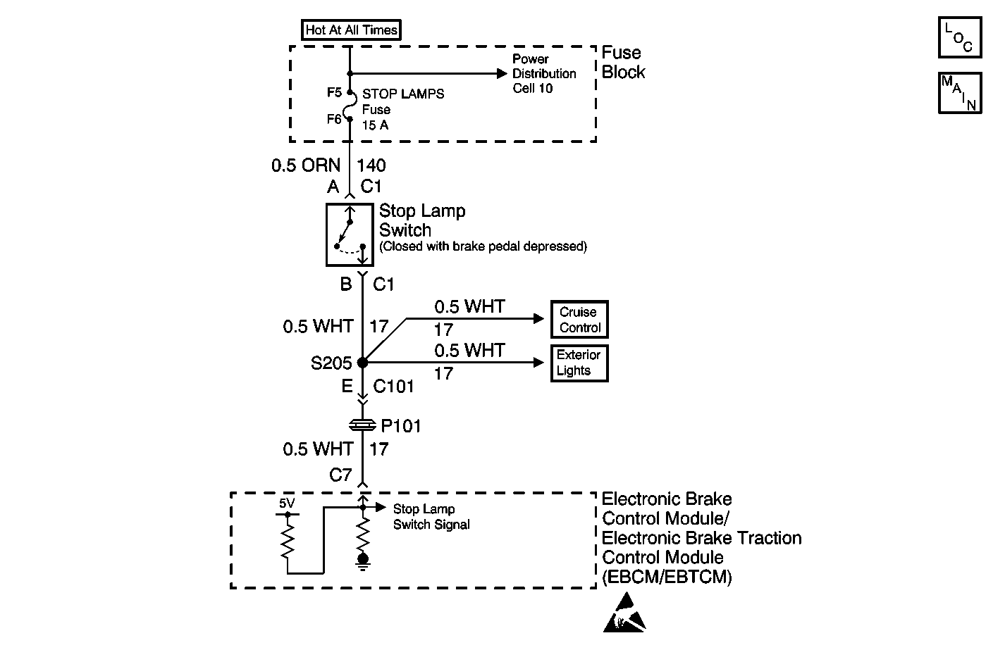
Circuit Description
This DTC occurs when internal self-checking safety logic has determined that the Stoplamp Switch is continuously on. This is important because the TCS can not be activated when the Stoplamp Switch is on.
Conditions for Setting the DTC
DTC C1294 can be set if the vehicle speed reaches at least 40 km/h (25 mph). If the brake lamp switch is always on during two consecutive drive cycles, a malfunction exists.
Action Taken When the DTC Sets
| • | A malfunction DTC is stored. |
| • | TCS is disabled. |
| • | Traction Control indicator is turned on. |
| • | ABS remains functional. |
Conditions for Clearing the DTC
| • | Condition for DTC is no longer present and scan tool clear DTC function is used. |
| • | 100 ignition cycles have passed with no DTCs detected. |
Diagnostic Aids
| • | Possible causes: |
| - | Stoplamp switch circuit shorted to voltage. |
| - | Stoplamp switch misadjusted or shorted. |
| - | Sticking contacts inside stoplamp switch. |
| - | Binding pedal. |
| • | It is very important that a thorough inspection of the wiring and connectors be performed. Failure to carefully and fully inspect wiring and connectors may result in misdiagnosis, causing part replacement with reappearance of the malfunction. |
Step | Action | Value(s) | Yes | No |
|---|---|---|---|---|
1 | Was the Diagnostic System Check performed? | -- | ||
2 | Observe the rear brake lamps. Are the brake lamps illuminated without pressure applied to the brake pedal? | -- | ||
3 | Disconnect the Stoplamp switch connector C1. Are the brake lamps still illuminated? | -- | ||
4 |
Is any voltage present on CKT 17 without pressure applied to the brake pedal? | -- | ||
5 | Repair short to voltage in CKT 17. Refer to Wiring Repairs in Wiring Systems. Is the repair complete? | -- | -- | |
6 | Adjust or replace the Stoplamp switch as necessary. Refer to Stop Lamp Switch Adjustment or Stop Lamp Switch Replacement in Hydraulic Brakes. Is the repair complete? | -- | -- | |
7 |
(NOTE: A drive cycle consists of starting the engine, driving above 40 km/h (25 mph) back to 0 km/h (0 mph) and then turning the ignition OFF.) Was DTC C1294 set in the last two drive cycles? | -- | -- | |
8 | Replace the EBCM/EBTCM. Refer to Electronic Brake Control Module/Electronic Brake and Track Control Module Replacement . Is the replacement complete? | -- | -- |
