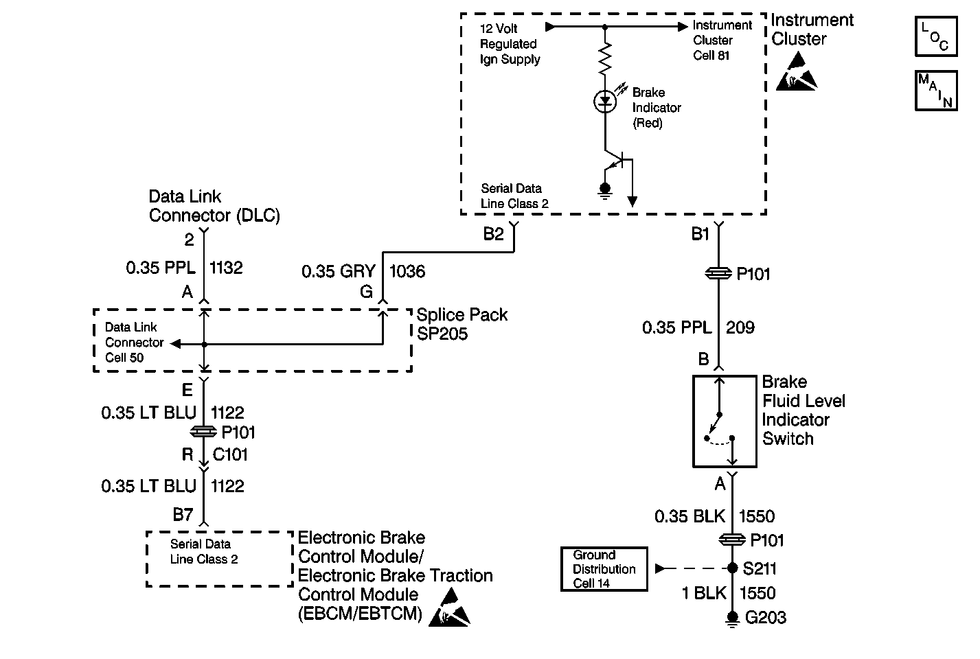
Circuit Description
When the master cylinder is low on brake fluid the brake fluid level indicator switch grounds the circuit and turns on the RED brake indicator in the instrument cluster, then the instrument cluster sends a class 2 message to the EBTCM. If the low brake fluid message is sent from the IPC to the EBTCM, TCS will be disabled and a Diagnostic Trouble Code (DTC) will be set.
Conditions for Setting the DTC
DTC C1247 is set when the EBTCM receives a class 2 message from the instrument cluster that the brake fluid is low in the master cylinder reservoir.
Action Taken When the DTC Sets
| • | A malfunction DTC is stored. |
| • | TCS is disabled. |
| • | TCS Indicator (TRAC OFF) is turned on. |
| • | RED Brake indicator is turned on. |
| • | Service Vehicle Soon indicator is turned on. |
Conditions for Clearing the DTC
Condition for DTC is no longer present or scan tool clear DTC function is used.
Diagnostic Aids
| • | Possible causes for DTC C1247 to set are: |
| - | Any leaks in hydraulic brake system (such as brake pipes, wheel cylinders, calipers, or master cylinder). |
| - | Brake fluid level indicator switch malfunction. |
| - | Brake fluid level indicator switch line (CKT209) short to ground. |
| • | It is very important that a thorough inspection of the wiring, connectors, and the hydraulic brake system components be performed. Failure to carefully and fully inspect wiring, connectors, and hydraulic brake system components may result in misdiagnosis, causing part replacement with reappearance of the malfunction. |
| • | If an intermittent malfunction exists refer to Intermittents and Poor Connections Diagnosis in Wiring Systems. |
Step | Action | Value(s) | Yes | No | ||||||||||
|---|---|---|---|---|---|---|---|---|---|---|---|---|---|---|
1 | Was the Diagnostic System Check performed? | -- | ||||||||||||
2 | Inspect the Master Cylinder brake fluid level. Is the brake fluid at the proper level in the Master Cylinder reservoir? | -- | ||||||||||||
3 |
Is there any signs of leakage with the above components? | -- | ||||||||||||
4 | Repair and/or replace any components that shows any sign of leakage. Is the repair complete? | -- | -- | |||||||||||
5 |
Are there any signs of poor terminal contact, corrosion or damage terminal(s)? | -- | ||||||||||||
6 |
Is the repair complete? | -- | -- | |||||||||||
7 |
Is continuity present between terminal A and terminal B of Brake Fluid Level Indicator Switch with the brake fluid at normal level? | -- | ||||||||||||
8 | Replace the Brake Fluid Level sensor. Refer to Brake Fluid Level Indicator Switch Replacement in Hydraulic Brakes. Is the repair complete? | -- | -- | |||||||||||
9 |
Is continuity present between terminal B of Brake Fluid Level Indicator Switch connector and a known good ground? | -- | ||||||||||||
10 | Repair CKT 209 for an short to ground. Refer to Wiring Repairs in Wiring Systems. Is the repair complete? | -- | -- |
