Refer to
Heated Oxygen Sensors
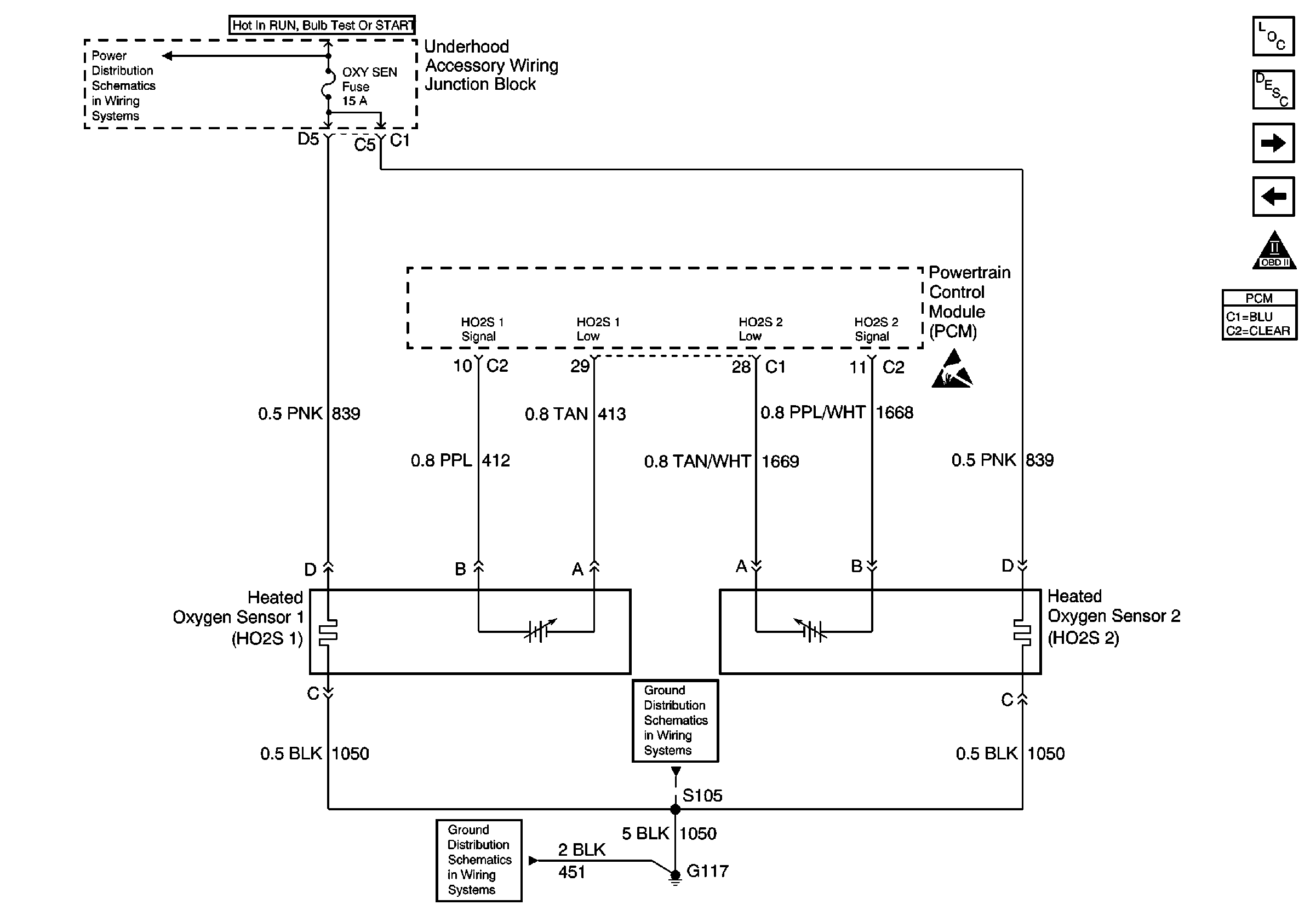
in Engine Controls Schematics.
Circuit Description
To control emissions of Hydrocarbons (HC), Carbon Monoxide (CO), and Oxides of Nitrogen (NOx), a three-way catalytic converter is used. The catalyst within the converter promotes a chemical reaction which oxidizes the HC and CO present in the exhaust gas, converting them into harmless water vapor and carbon dioxide. The catalyst also reduces NOx, converting NOx to nitrogen. The PCM has the ability to monitor this process using the HO2S 1 and the HO2S 2 heated oxygen sensors. The HO2S 1 sensor produces an output signal which indicates the amount of oxygen present in the exhaust gas entering the three-way catalytic converter. The HO2S 2 sensor produces an output signal which indicates the oxygen storage capacity of the catalyst this in turn indicates the catalysts ability to convert exhaust gases efficiently. If the catalyst is operating efficiently, the HO2S 1 signal will be far more active than that produced by the HO2S 2 sensor. If the HO2S 2 signal voltage remains excessively low for an extended period of time, DTC P0137 will be set.
Conditions for Running the DTC
| • | Active TP, MAP, MAF, IAT, ECT, fuel injector circuit, or EVAP DTCs are not present. |
| • | System voltage is between 9.0 and 18.0 volts. |
| • | ECT above 65°C (149°F) |
| • | Closed loop commanded air/fuel ratio is between 14.5 and 14.8. |
| • | Throttle angle is between 3 percent and 40 percent. |
| • | AIR pump commanded OFF. |
Conditions for Setting the DTC
| • | HO2S 2 signal voltage remains below 10 mV during normal closed loop operation for more than 3.5 minutes. |
| OR |
| • | HO2S 2 signal voltage remains below 600 mV during power enrichment mode fuel control operation for more than 10 seconds. |
| OR |
Action Taken When the DTC Sets
| • | The PCM will illuminate the malfunction indicator lamp (MIL) during the second consecutive trip in which the diagnostic test has been run and failed. |
| • | The PCM will store conditions which were present when the DTC set as Freeze Frame/Failure Records data. |
Conditions for Clearing the MIL/DTC
| • | The PCM will turn OFF the malfunction indicator lamp (MIL) during the third consecutive trip in which the diagnostic has run and passed. |
| • | The history DTC will clear after 40 consecutive warm-up cycles have occurred without a malfunction. |
| • | The DTC can be cleared by using a scan tool. |
Diagnostic Aids
Inspect for the following conditions:
| • | Heated oxygen sensor wiring--The sensor pigtail may be mispositioned and contacting the exhaust system. |
| • | Poor PCM to engine grounds--Refer to Ground Distribution Schematics . |
| • | Fuel pressure--A condition which causes a lean exhaust can cause DTC P0137 to set. The system will go lean if pressure is too low. The PCM can compensate for some decrease. However, if fuel pressure is too low, a DTC P0137 may be set. Refer to Fuel System Diagnosis . |
| • | Lean injectors--Perform Fuel Injector Balance Test . |
| • | Vacuum leaks--Inspect for disconnected or damaged vacuum hoses and for vacuum leaks at the intake manifold, throttle body, EGR system, and Crankcase Ventilation system. Refer to Visual/Physical Inspection in Symptoms . |
| • | Exhaust leaks-- An exhaust leak may cause outside air to be pulled into the exhaust gas stream past the HO2S, causing the DTC P0137 to set. Inspect for exhaust leaks near the HO2S 2 sensor. |
| • | Fuel contamination--Water, even in small amounts, can be delivered to the fuel injectors. The water can cause a lean exhaust to be indicated. Excessive alcohol in the fuel can also cause this condition. Refer to Alcohol/Contaminants-in-Fuel Diagnosis . |
Test Description
The numbers below refer to the step numbers on the diagnostic table:
Step | Action | Values | Yes | No |
|---|---|---|---|---|
1 | Did you perform the Powertrain On-Board Diagnostic (OBD) System Check? | -- | ||
2 |
Important: During this step, observe the pre-catalyst HO2S voltage parameters. If the pre-catalyst parameters remain below 400mV refer to Diagnostic Aids.
Does the HO2S 2 voltage measure below the specified value? | 10 mV (600 mV During Power Enrichment) | ||
Does scan tool indicate DTC P0137 failed this ignition? | -- | Go to Diagnostic Aids | ||
4 | Disconnect HO2S 2 and jumper the HO2S 2 low circuit (PCM side) to ground. Does scan tool indicate HO2S 2 voltage near the specified value? | 450 mV | Go to Diagnostic Aids | |
5 |
Is the HO2S 2 signal circuit shorted? | -- | ||
6 | Repair the HO2S 2 signal circuit. Refer to Wiring Repairs in Wiring Systems. Did you complete the repair? | -- | -- | |
|
Important: : Replacement PCM must be programmed. Replace the PCM. Refer to Powertrain Control Module Replacement/Programming . Did you complete the replacement? | -- | -- | ||
8 |
Does the DTC set? | -- | System OK |
