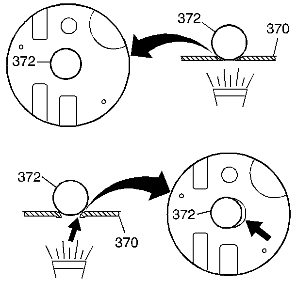
Notice: Do NOT use any type of grease to retain parts during the assembly of
this unit. Using greases other than the recommended assembly lube changes
the transaxle fluid characteristics. Using greases other than the recommended
assembly lube causes undesirable shift conditions and/or filter clogging.
Use TRANSJEL™ J 36850 or equivalent during the assembly
of this unit.
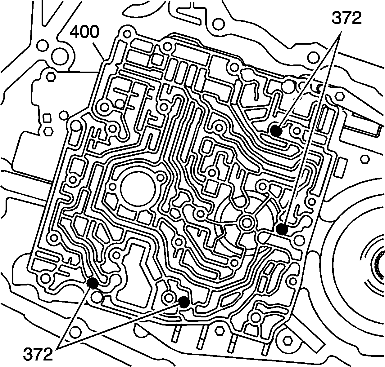
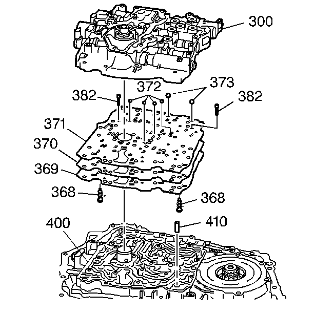
- Install the ball check valves (372) into the case cover. Use the
J 36850
to
retain the ball check valves in their proper locations.
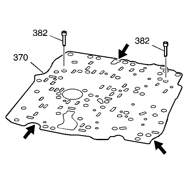
- Install the gasket and the spacer plate (370).
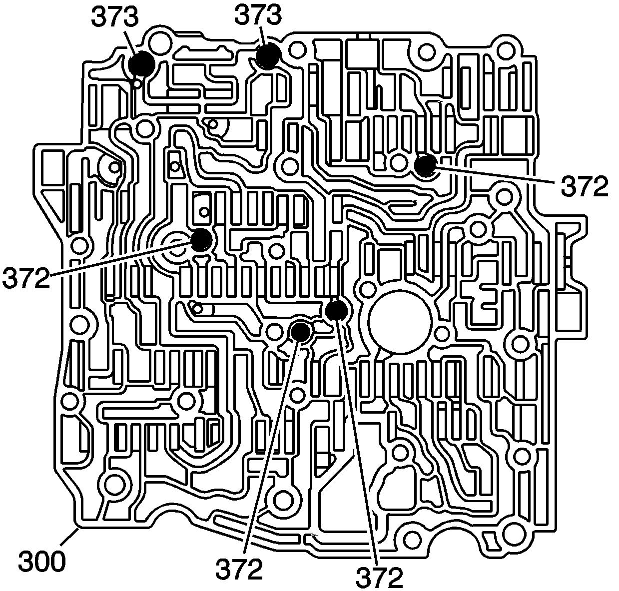
- Install the ball check valves (372 and 373) into the valve body. Use the
J 36850
to retain the ball check valves in their proper locations.
Important: Do NOT use impact type tools on the valve body or on the oil pump.
- Install the gasket (371) and the valve body (300).
Notice: Refer to Fastener Notice in the Preface section.
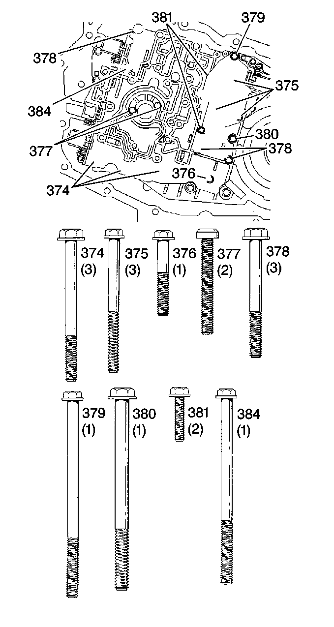
- Install the valve body bolts (374-381 and 384).
Tighten
| • | Tighten the M6 X 1.0 X 20 bolt to 8 N·m (70 lb in). |
| • | Tighten the M6 X 1.0 X 30 bolt to 12 N·m (106 lb in). |
| • | Tighten the M6 X 1.0 X 45 bolt to 12 N·m (106 lb in). |
| • | Tighten the M6 X 1.0 X 55 bolt to 11 N·m (97 lb in). |
| • | Tighten the M6 X 1.0 X 60 bolt to 12 N·m (106 lb in). |
| • | Tighten the M6 X 1.0 X 65 bolt to 12 N·m (106 lb in). |
| • | Tighten the M6 X 1.0 X 85 bolt to 11 N·m (97 lb in). |
| • | Tighten the M6 X 1.0 X 90 bolt to 11 N·m (97 lb in). |
| • | Tighten the M8 X 1.0 X 90 bolt to 25 N·m (18 lb ft). |
Important: Do NOT use impact type tools on the valve body or on the oil pump.
- Install the oil pump. Refer to
Oil Pump Replacement
.
- Install the case side cover. Refer to
Control Valve Body Cover Replacement
.
Important: It is recommended that transmission adaptive pressure (TAP) information be reset.
Resetting the TAP values using a scan tool will erase all learned values in all cells. As a result, The ECM, PCM or TCM will
need to relearn TAP values. Transmission performance may be affected as new TAP values are learned.
- Reset the TAP values. Refer to
Adapt Function
.


