For 1990-2009 cars only
Tools Required
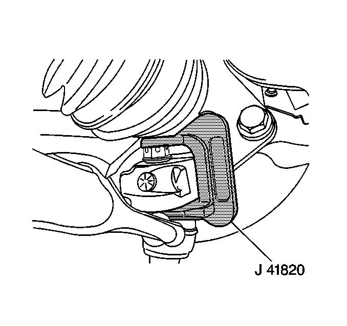
J 41820 Ball Joint/Stud Separator
Removal Procedure
- Raise and support the vehicle. Refer to Lifting and Jacking the Vehicle in General Information.
- Remove the tire and wheel. Refer to Tire and Wheel Removal and Installation in Tires and Wheels.
- Drill a pilot hole through the rivets.
- Drill the remainder of the rivets.
- Use a hammer and a chisel in order to remove the remainder of the rivet heads.
- Remove the cotter pin from the ball stud.
- Loosen the ball stud nut.
- Install theJ 41820 over the ball stud and lower control arm.
- Rotate the ball stud nut counterclockwise in order to separate the ball stud from the steering knuckle.
- Remove theJ 41820 .
- Remove the ball stud nut.
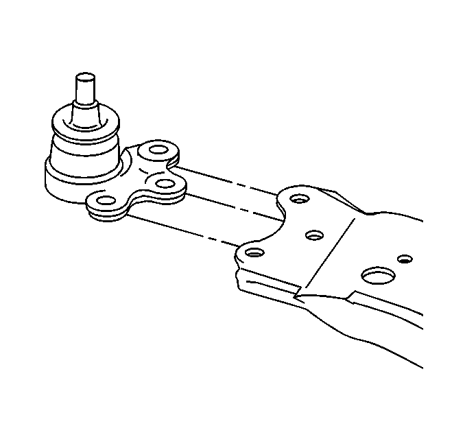
- Remove the ball stud from the lower control arm.


Installation Procedure
- Install the ball stud to the lower control arm.
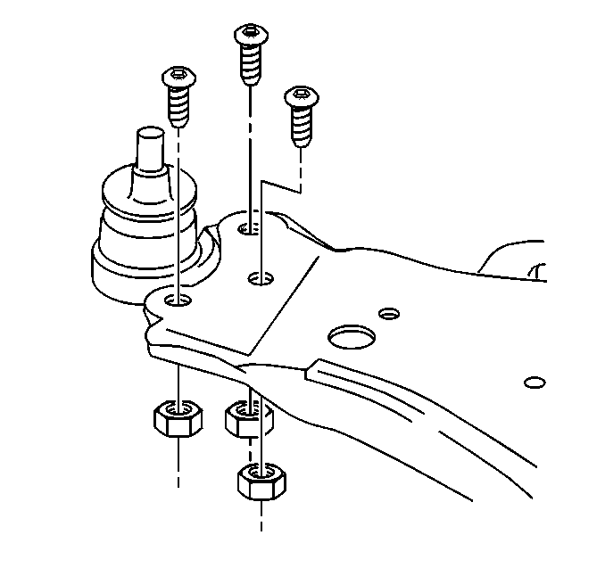
- Install the NEW ball stud bolts facing down, away from the ball stud.
- Install the NEW ball stud nuts.
- Install the ball stud to the steering knuckle.
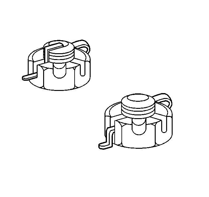
- Install the ball stud castle nut.
- Install a new cotter pin and bend the ends.
- Install the tire and wheels. Refer to Tire and Wheel Removal and Installation in Tires and Wheels.
- Lower the vehicle.
- Check the wheel alignment. Refer to Wheel Alignment Measurement in Wheel Alignment.


Notice: Refer to Fastener Notice in the Preface section.
Tighten
Tighten the NEW ball stud nuts to 68 N·m (50 lb ft).
Tighten
Tighten the nut to 20 N·m (15 lb ft) plus an additional
120 degrees

