GM Service Manual Online
For 1990-2009 cars only
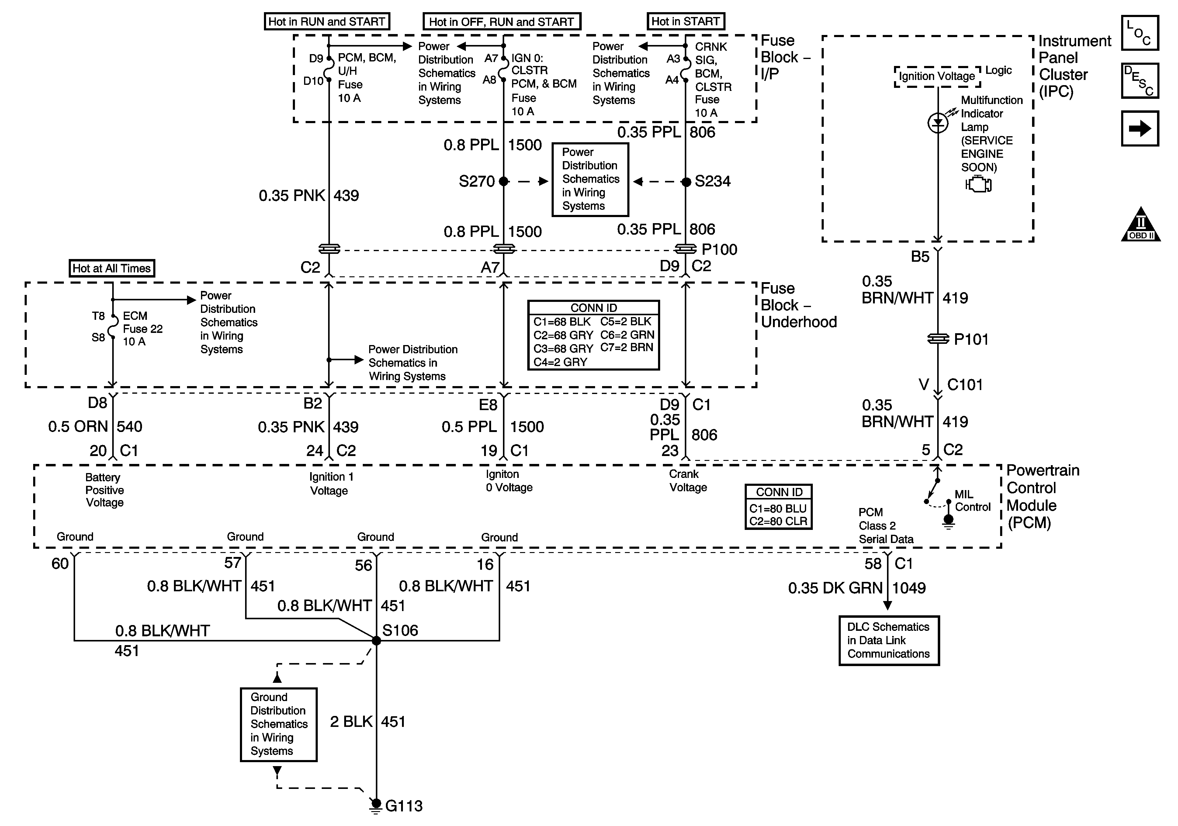
Figure 1:

Module Power, Ground, Serial Data, and MIL

Object Number: 1217236  Size: FS
Master Electrical Component List
Powertrain Control Module Description
Engine Data Sensors - 5 Volt and Low Reference
OBD II Symbol Description Notice
Fuse Block - Underhood IGN 1 Fuse
Fuse Block - I/P CRNK SIG, BCM, CLSTR, IGN0:CLSTR, PCM, BCM, and PRK/LCK Fuses
Fuse Block - Underhood B+ Bus
Fuse Block - I/P TRN/SIG, AIR BAG, CLSTR, and PCM, BCM U/H Fuses, Fuse Block - Underhood CRANK and IGN MAIN Relays
G100, G113, and G171
Data Link Connector (DLC) Schematics
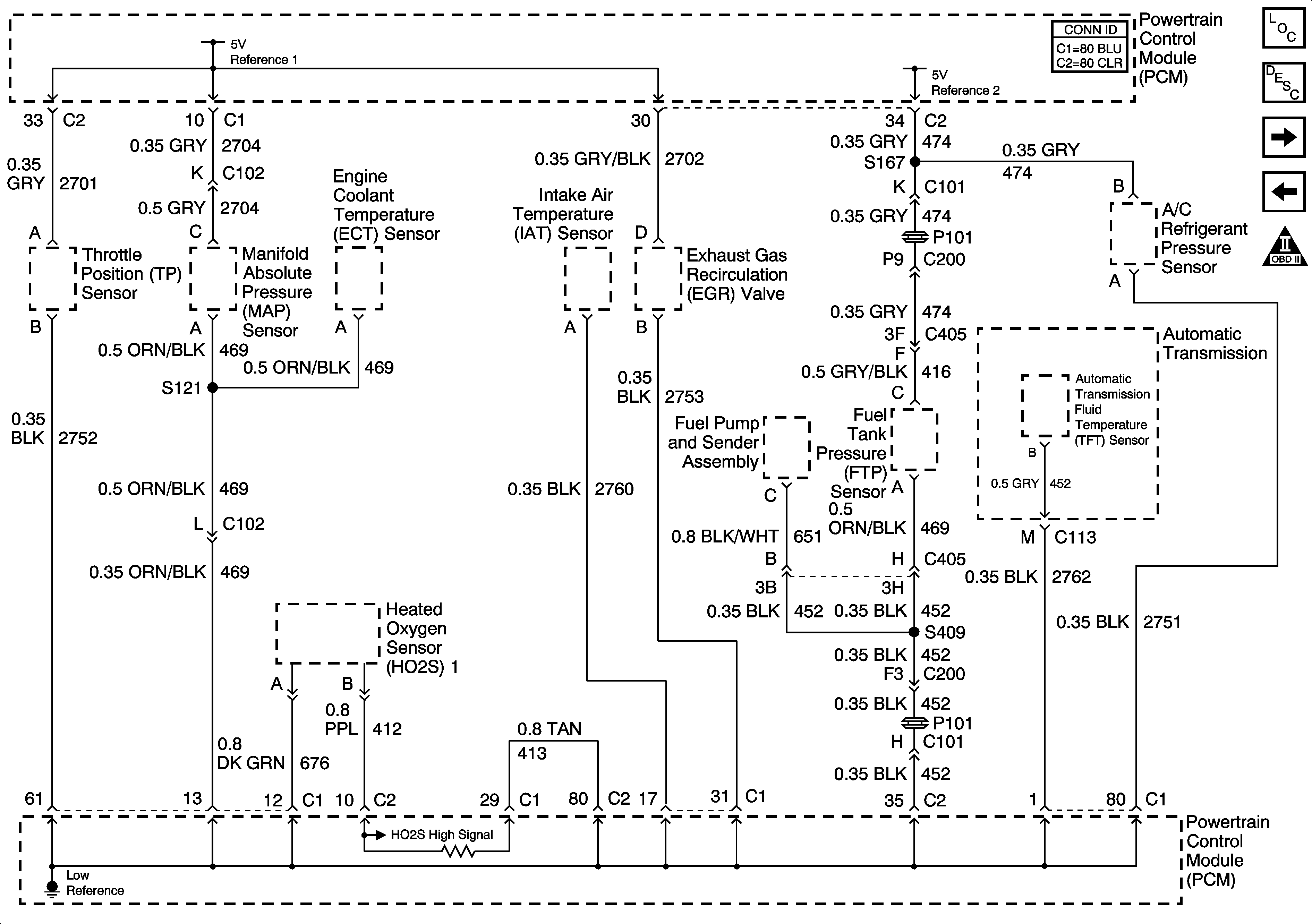
Figure 2:

Engine Data Sensors - 5-Volt and Low Reference

Object Number: 1219228  Size: FS
Master Electrical Component List
Powertrain Control Module Description
Engine Data Sensors - Pressure and Temperature
Module Power, Ground, Serial Data, and MIL
OBD II Symbol Description Notice
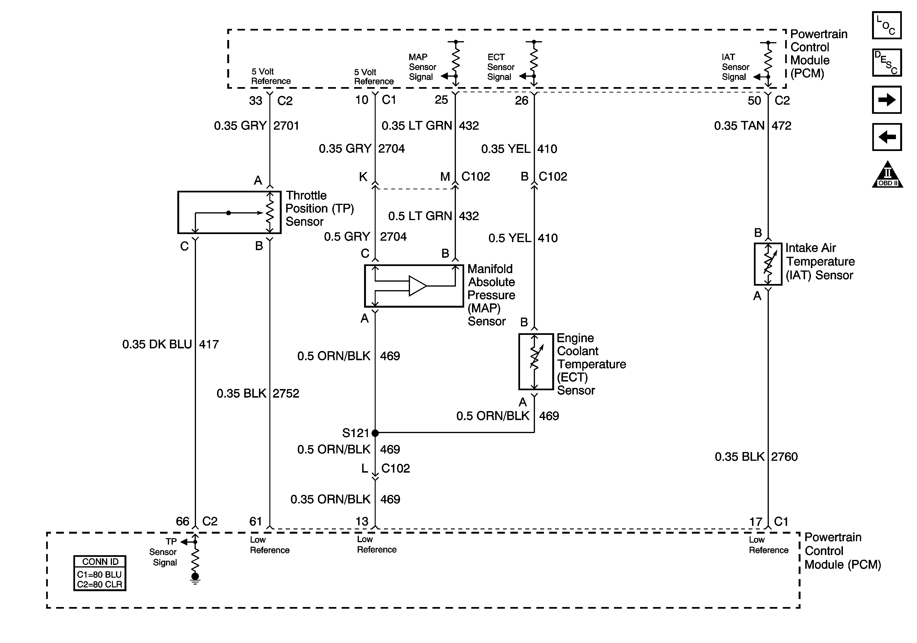
Figure 3:

Engine Data Sensors - Pressure and Temperature


Object Number: 1353607  Size: FS
Master Electrical Component List
Powertrain Control Module Description
Engine Data Sensors - MAF, VSS
Engine Data Sensors - 5 Volt and Low Reference
OBD II Symbol Description Notice
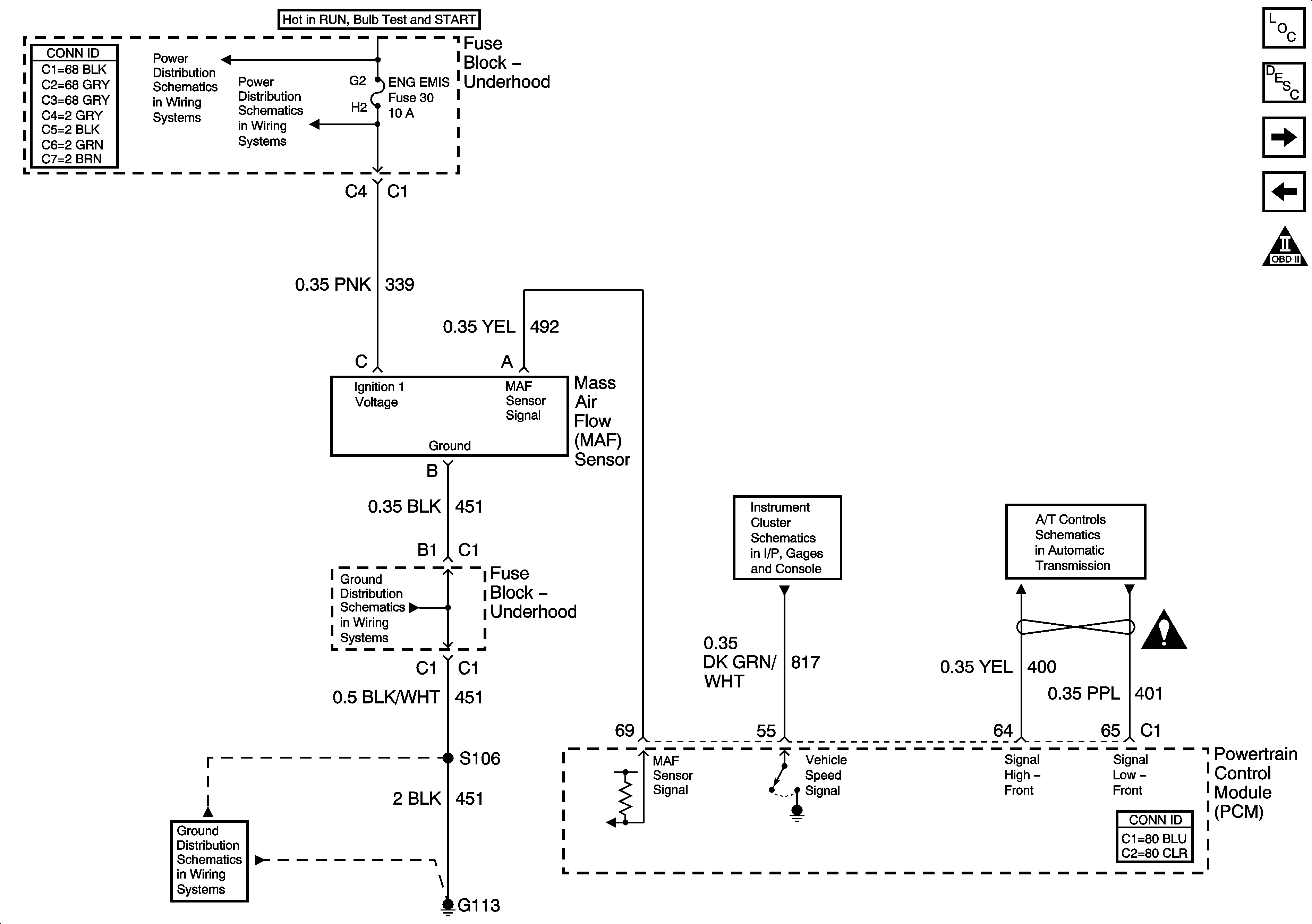
Figure 4:

Engine Data Sensors - MAF, VSS


Object Number: 1275561  Size: FS
Master Electrical Component List
Powertrain Control Module Description
Oxygen Sensors
Engine Data Sensors - Pressure and Temperature
OBD II Symbol Description Notice
Fuse Block - Underhood B+ Bus
Fuse Block - Underhood ENG EMIS Fuse
G100, G113, and G171
Gages
Fluid Pressure Manual Valve Position Switch, ISS Sensor, and VSS
Engine Controls Schematic Icons
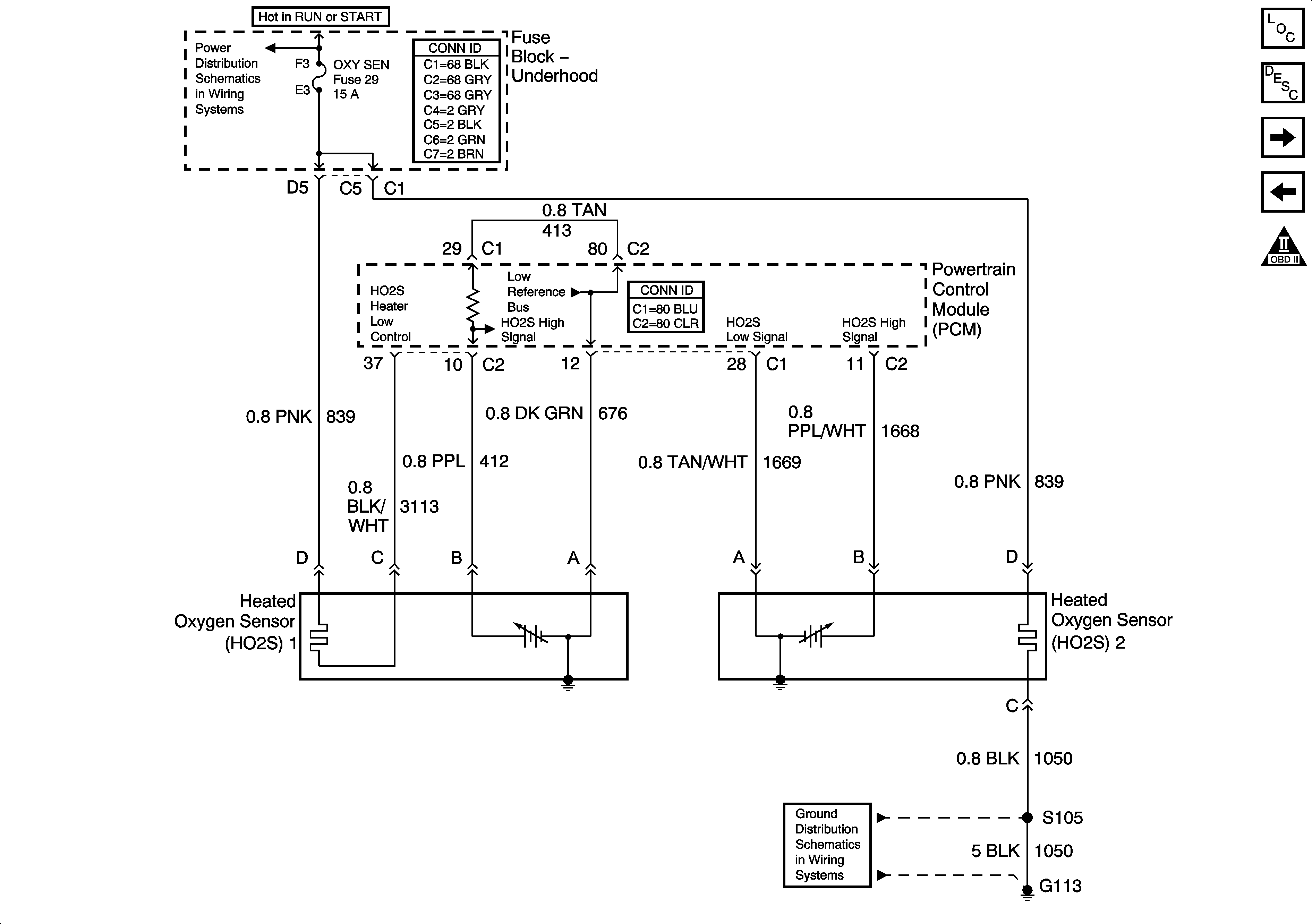
Figure 5:

Oxygen Sensors


Object Number: 1275565  Size: FS
Master Electrical Component List
Powertrain Control Module Description
Ignition Control Module
Engine Data Sensors - MAF, VSS
OBD II Symbol Description Notice
Fuse Block - Underhood B+ Bus
G100, G113, and G171
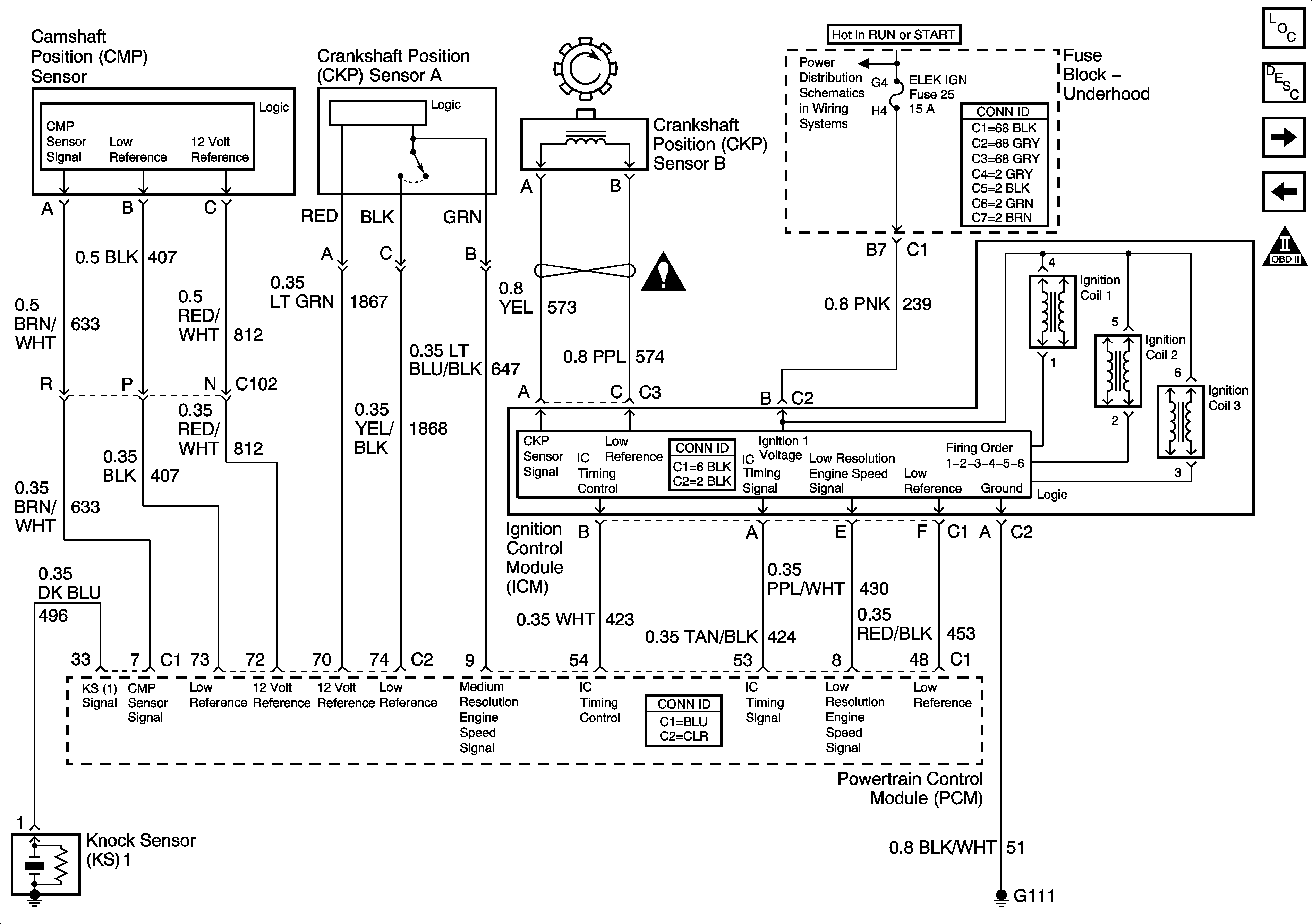
Figure 6:

Ignition Control Module


Object Number: 1217241  Size: FS
Master Electrical Component List
Electronic Ignition (EI) System Description
Fuel Pump Controls
Oxygen Sensors
OBD II Symbol Description Notice
Fuse Block - Underhood B+ Bus
Engine Controls Schematic Icons
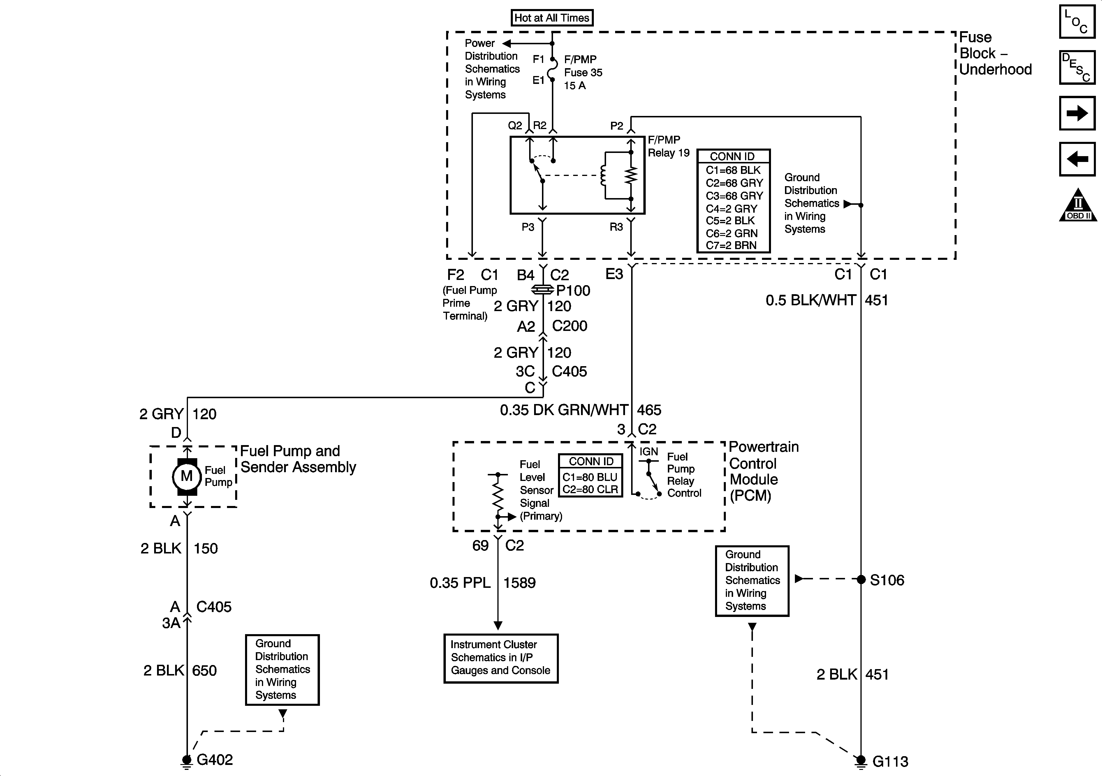
Figure 7:

Fuel Pump Controls


Object Number: 1219230  Size: FS
Master Electrical Component List
Fuel System Description
Fuel Injectors
Ignition Control Module
OBD II Symbol Description Notice
Fuse Block - Underhood B+ Bus
G100, G113, and G171
G402, Page 1 of 2
Gages
G100, G113, and G171
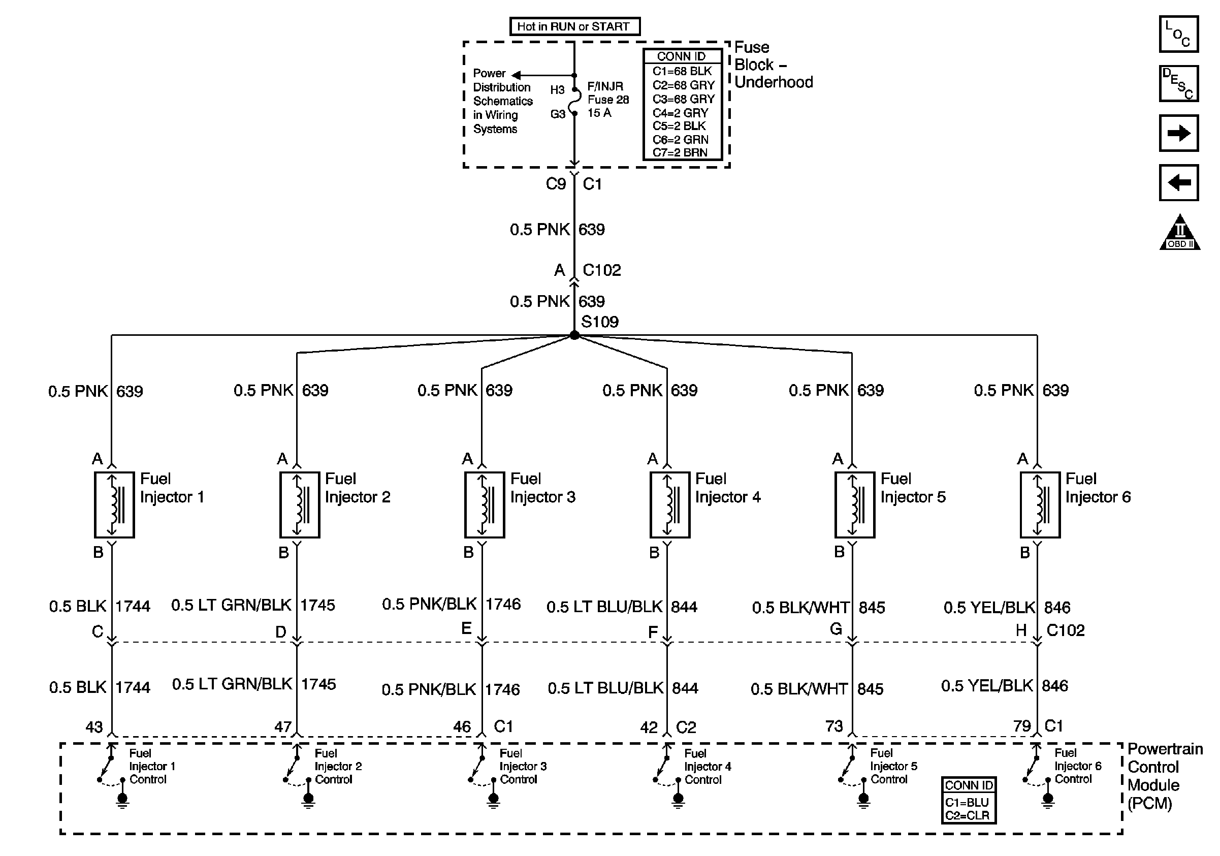
Figure 8:

Fuel Injectors


Object Number: 789741  Size: FS
Master Electrical Component List
Fuel System Description
EVAP Controls and FTP Sensor
Fuel Pump Controls
OBD II Symbol Description Notice
Fuse Block - Underhood B+ Bus
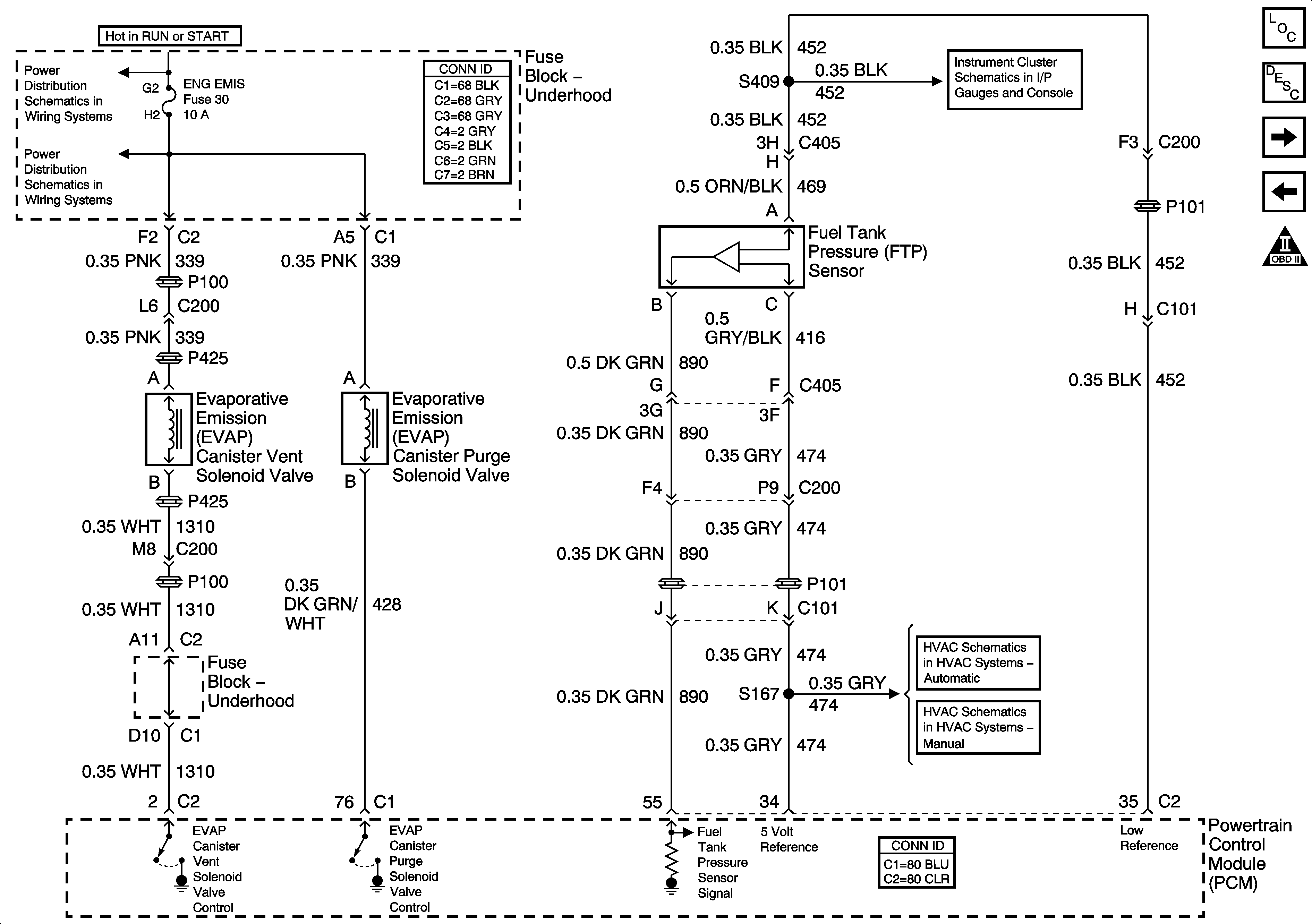
Figure 9:

EVAP Controls and FTP Sensor


Object Number: 1219269  Size: FS
Master Electrical Component List
Evaporative Emission Control System Description
AIR, EGR, and IAC Controls
Fuel Injectors
OBD II Symbol Description Notice
Fuse Block - Underhood B+ Bus
Fuse Block - Underhood ENG EMIS Fuse
Gages
Compressor Controls
Compressor Controls
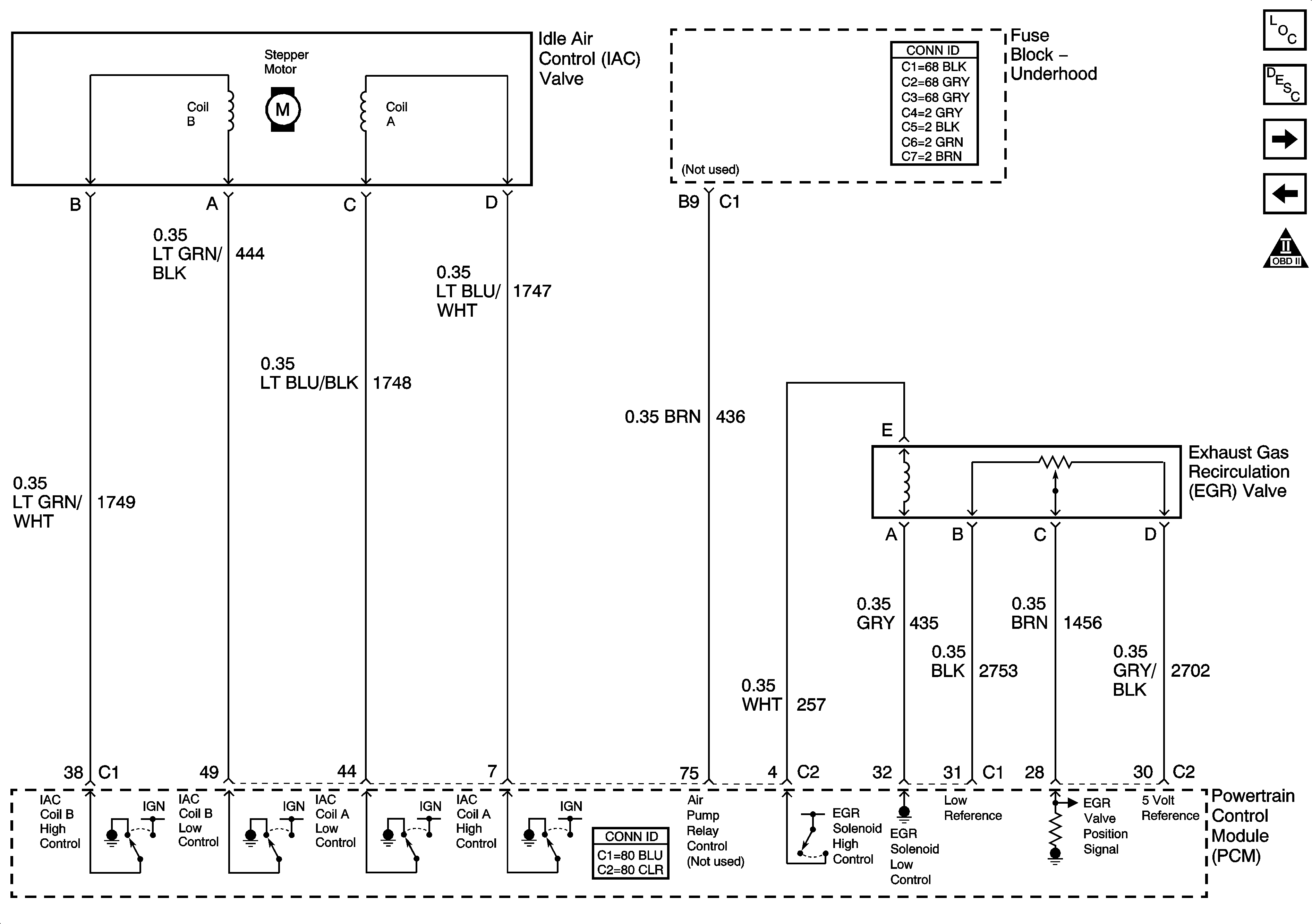
Figure 10:

AIR, EGR, and IAC Controls


Object Number: 1275566  Size: FS
Master Electrical Component List
Exhaust Gas Recirculation (EGR) System Description
Controlled/Monitored PCM References
EVAP Controls and FTP Sensor
OBD II Symbol Description Notice
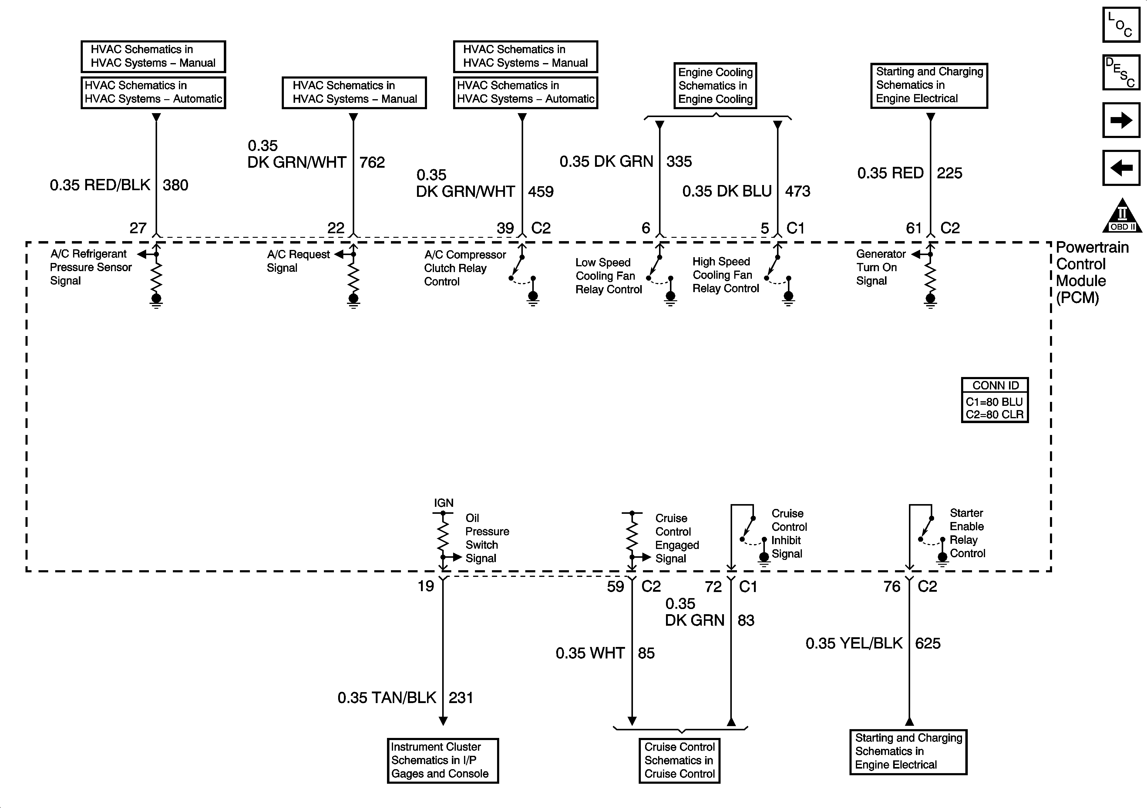
Figure 11:

PCM References - Controlled/Monitored Subsystem

Object Number: 1217243  Size: FS
Master Electrical Component List
Powertrain Control Module Description
PCM References - Transmission Controls
AIR, EGR, and IAC Controls
OBD II Symbol Description Notice
Compressor Controls
Compressor Controls
Compressor Controls
Compressor Controls
Compressor Controls
Engine Cooling Schematics
Charging
Indicators, Page 2 of 2
Cruise Control Schematics
Starting
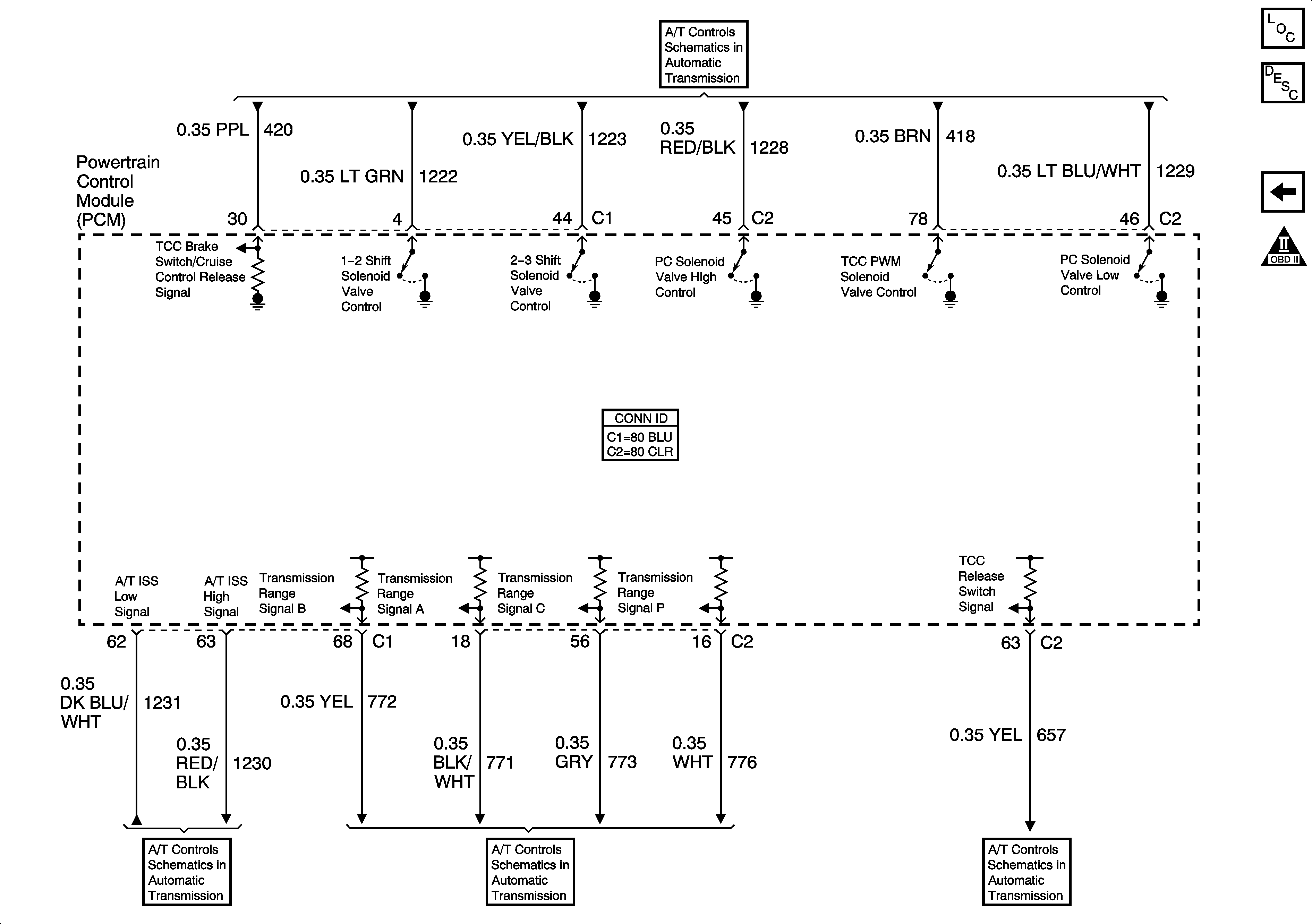
Figure 12:

PCM References - Transmission Controls


Object Number: 852266  Size: FS
Master Electrical Component List
Powertrain Control Module Description
Controlled/Monitored PCM References
OBD II Symbol Description Notice
Solenoid Controls and TFT Sensor
Fluid Pressure Manual Valve Position Switch, ISS Sensor, and VSS
Internal Mode Switch (IMS)
Fluid Pressure Manual Valve Position Switch, ISS Sensor, and VSS