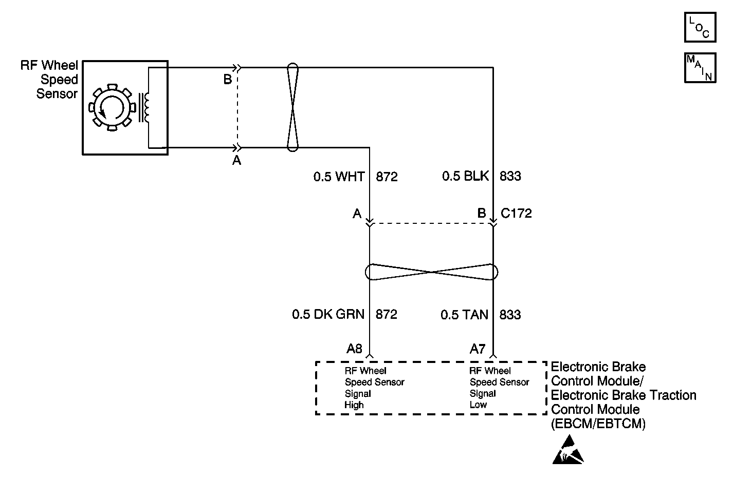
Circuit Description
The speed sensor used on this vehicle is a multiple pole magnetic pickup. This sensor produces an AC signal when a toothed ring passes the wheel speed sensor. The EBCM uses the frequency to calculate the wheel speed.
Conditions for Running the DTC
| • | DTCs C1232-C1235 are not set. |
| • | The brake pedal is not pressed. |
Conditions for Setting the DTC
| • | The change in wheel speed is more than 24 km/h (15 mph) in 0.01 second. |
| • | The above condition must occur 5 times with less than 1.00 second between each occurrence. |
Action Taken When the DTC Sets
| • | The ABS/TCS disables. |
| • | The EBCM turns on the ABS and the TRAC OFF (if equipped) indicator(s). |
Conditions for Clearing the DTC
| • | Condition for DTC is no longer present and scan tool clear DTC function is used. |
| • | 100 ignition cycles have passed with no DTC(s) detected. |
Diagnostic Aids
| • | It is very important that a thorough inspection of the wiring and connectors be performed. Failure to carefully and fully inspect wiring and connectors may result in misdiagnosis, causing part replacement with reappearance of the malfunction. |
| • | An intermittent malfunction can be caused by poor connections, broken insulation, or a wire that is broken inside the insulation. |
| • | If an intermittent malfunction exists refer to Testing for Intermittent Conditions and Poor Connections in Wiring Systems. |
Test Description
The numbers below refer to the step numbers on the diagnostic table.
-
This step tests the wheel speed sensor for the proper resistance value.
-
This step ensures that the wheel speed sensor generates the proper voltage.
-
This step tests whether the wheel speed sensor circuits are shorted together.
Step | Action | Value(s) | Yes | No | ||||||
|---|---|---|---|---|---|---|---|---|---|---|
1 | Did you perform the ABS Diagnostic System Check? | -- | Go to Step 2 | |||||||
2 |
Does the scan tool indicate the suspect wheel speed varies from the speeds of the other wheels? | -- | Go to Step 3 | Go to Testing for Intermittent Conditions and Poor Connections in Wiring Systems | ||||||
3 | Inspect the following components for physical damage:
Did you find and correct the condition? | -- | Go to Step 11 | Go to Step 4 | ||||||
Does the resistance measure within the specified range? | 850-1350 ohms | Go to Step 5 | Go to Step 9 | |||||||
Does the AC voltage measure greater than the specified value? | 100 mV | Go to Step 6 | Go to Step 9 | |||||||
6 | Inspect for poor connections/terminal tension at the wheel speed sensor harness connector. Refer to Testing for Intermittent Conditions and Poor Connections and Connector Repairs in Wiring Systems. Did you find and correct the condition? | -- | Go to Step 11 | Go to Step 7 | ||||||
Did you find and correct the condition? | -- | Go to Step 11 | Go to Step 8 | |||||||
8 | Inspect for poor connections/terminal tension at the EBCM harness connector. Refer to Testing for Intermittent Conditions and Poor Connections and Connector Repairs in Wiring Systems. Did you find and correct the condition? | -- | Go to Step 11 | Go to Step 10 | ||||||
9 | Replace the wheel speed sensor. Refer to Wheel Speed Sensor Replacement . Did you complete the replacement? | -- | Go to Step 11 | -- | ||||||
10 | Replace the EBCM. Refer to Electronic Brake Control Module Replacement . Did you complete the replacement? | -- | Go to Step 11 | -- | ||||||
11 |
Does the DTC reset? | -- | Go to Step 2 | System OK |
