For 1990-2009 cars only
Refer to
Indicator Lamps

.
Circuit Description
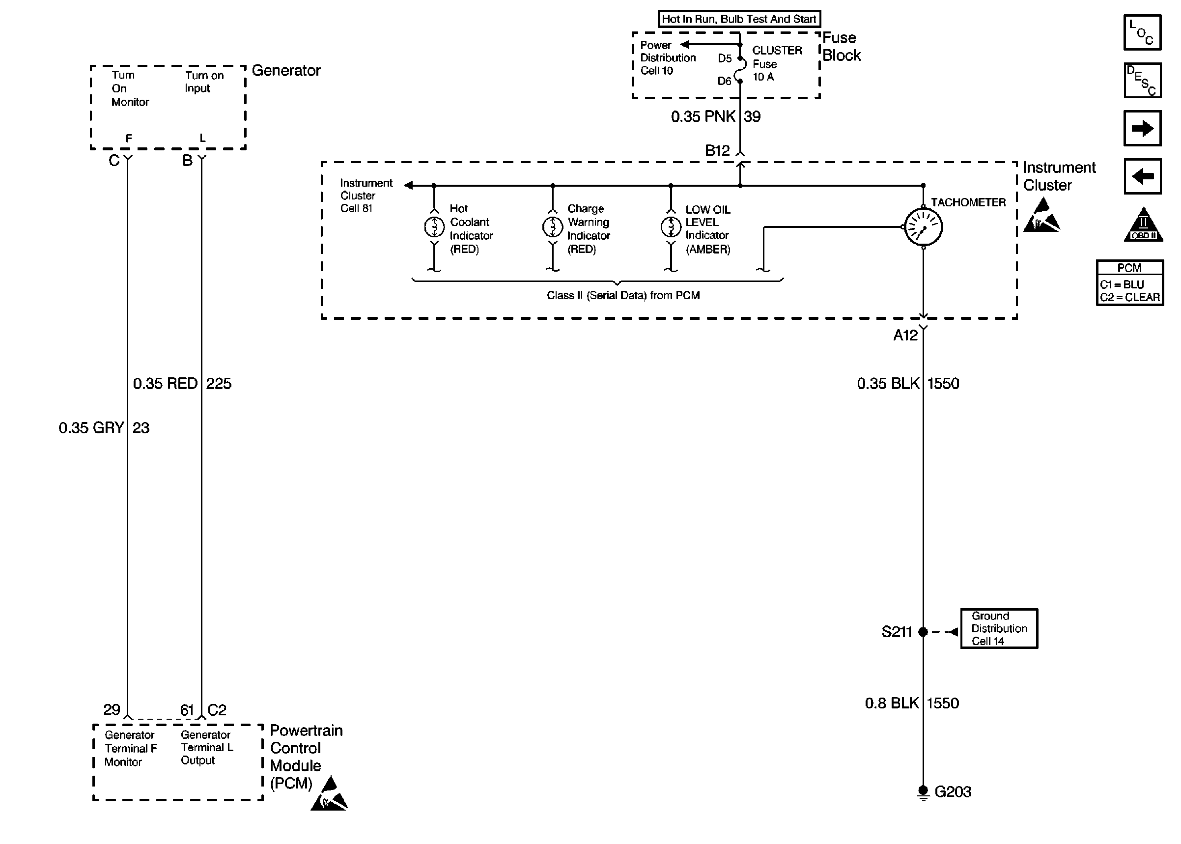
The PCM controls the pulse frequency in relationship to engine RPM, and sends the information class II to the Instrument Cluster.
Diagnostic Aids
Refer to Instrument Cluster in Electrical Diagnosis for additional diagnostic information.
Check for the following conditions:
| • | Poor connection at the PCM or instrument cluster. Inspect the harness connectors for backed out terminals, improper mating, broken locks, improperly formed or damaged terminals, and poor terminal to wire connection. Refer to Intermittents and Poor Connections Diagnosis , Connector Repairs , and Wiring Repairs . |
| • | Damaged harness. Inspect the wiring harness for damage. Refer to Intermittents and Poor Connections Diagnosis , Connector Repairs , and Wiring Repairs . |
Step | Action | Value(s) | Yes | No |
|---|---|---|---|---|
1 | Was Instrument Cluster diagnosis performed? | -- | ||
2 | Was the Powertrain On-Board Diagnostic System Check performed? | -- | ||
3 | Are there any DTCs set? | -- | ||
4 |
Does the scan tool RPM match the Instrument Cluster? | -- | System OK Refer to Diagnostic Aids | |
5 | Verify proper operation of scan tool. Connect scan tool to another vehicle and observe the RPM. Does scan tool match vehicle RPM? | -- | System OK Refer to Diagnostic Aids |
