Fuel Metering System Components
The fuel metering system is made up of the following parts:
| • | Throttle Body |
| • | Fuel Rail |
| • | Fuel Injectors. |
| • | Fuel Pressure Regulator |
| • | Idle Air Control Valve (IAC) |
| • | Throttle Position Sensor (TP) |
| • | Mass Air Flow Sensor (MAF) |
| • | Fuel Pump. |
| • | Fuel Pump Relay |
| • | Accelerator Controls |
| • | Power Train Control Module (PCM) |
| • | Crankshaft Position Sensor |
| • | Camshaft Position Sensor |
Basic System Operation
The fuel metering system starts with the fuel in the fuel tank. An electric fuel pump, located in the modular fuel sender assembly, picks up fuel through a fuel strainer and pumps fuel to the fuel rail through an in-pipe fuel filter to the fuel rail. The fuel pump is designed to provide fuel at a pressure above the pressure needed by the fuel injectors. A pressure regulator in the fuel rail keeps fuel available to the injectors at a constant pressure. Unused fuel is returned to the fuel tank by a separate pipe. For additional information on the fuel tank, in-pipe filter, modular fuel sender assembly and fuel pipes. Refer to Fuel Supply Component Description
Throttle Body Unit
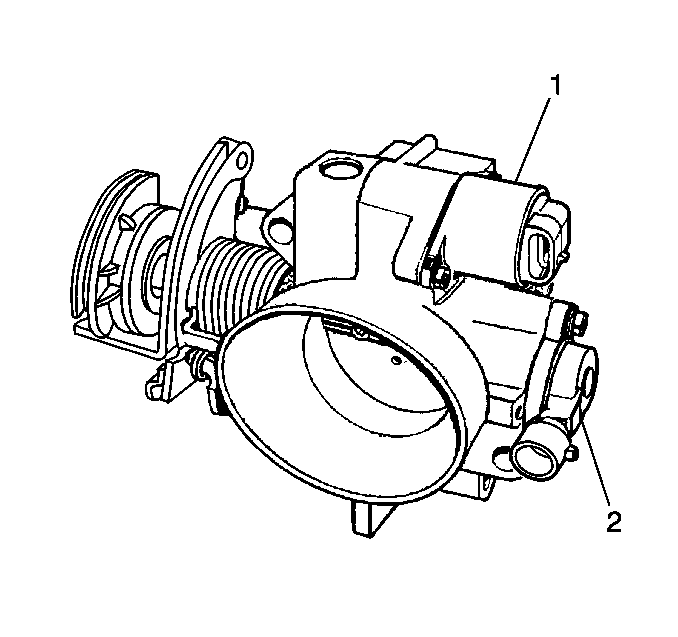
The throttle body has a throttle plate to control the amount of air delivered to the engine. The throttle position (TP) sensor and idle air control (IAC) sensor are mounted on the throttle body.
Vacuum ports located behind the throttle plate provide the vacuum signals needed by various components.
Fuel Rail
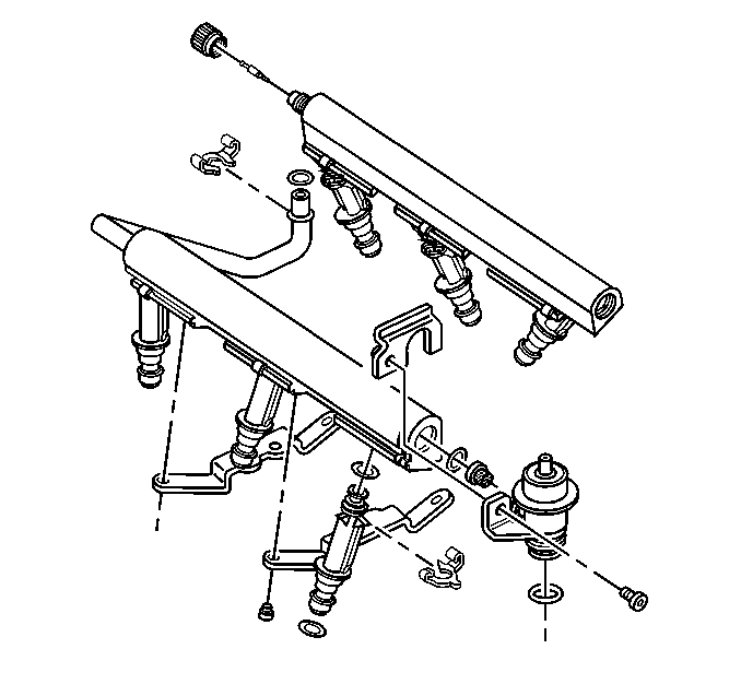
The fuel rail assembly is made up of two rails and carries the fuel injectors, the left hand rail, delivers fuel to the even cylinders (2,4,6) and the right hand rail delivers fuel to the odd cylinders (1,3, 5).
Fuel is delivered to the fuel inlet tube of the fuel rail by the fuel pipes. The fuel then goes through the fuel rail to the fuel pressure regulator. The fuel pressure regulator maintains a constant fuel pressure at the fuel injectors. Remaining fuel is then returned to the fuel tank.
Fuel Injector
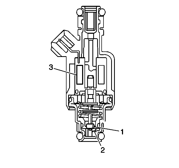
The Sequential Multiport Fuel Injection (SFI) fuel injector is a solenoid (3) operated device controlled by the PCM The PCM energizes the solenoid which opens a valve (1) to allow fuel delivery onto the director plate (2).
The fuel is injected under pressure in a conical spray pattern at the opening of the intake valve. Excess fuel not used by the injectors passes through the fuel pressure regulator before being returned to the fuel tank.
A fuel injector which is stuck partly open will cause a loss of fuel pressure after engine shut down, causing long crank times to be noticed on some engines.
Fuel Pressure Regulator
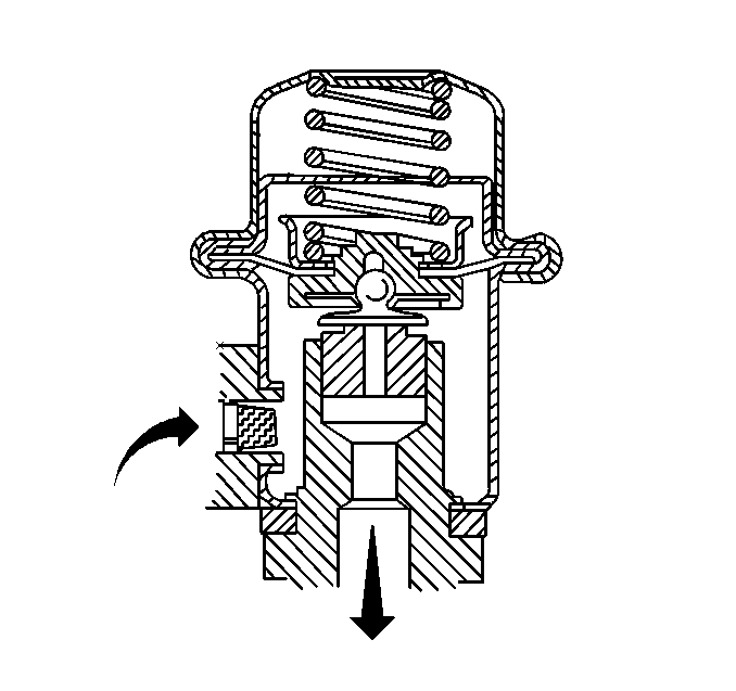
The fuel pressure regulator is a diaphragm-operated relief valve with fuel pump pressure on one side and manifold pressure on the other. The function of the fuel pressure regulator is to maintain the fuel pressure available to the fuel injectors at 3 times barometric pressure, adjusted for engine load.
The fuel pressure regulator attaches to the fuel rail on the fuel return side and may be serviced separately.
If the fuel pressure is too low, poor performance could result. If the pressure is to high, excessive odor and a Diagnostic Trouble Code (DTC) may result.
Idle Air Control (IAC) Valve
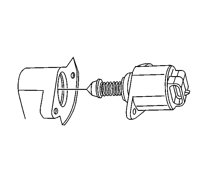
The purpose of the Idle Air Control (IAC) valve is to control engine idle speed, while preventing stalls due to changes in engine load. The IAC valve, mounted in the throttle body, controls bypass air around the throttle plate. By moving a conical valve, known as a pintle, in (to decrease air flow) or out (to increase air flow), a controlled amount of air can move around the throttle plate. If RPM is too low, the PCM will retract the IAC pintle, resulting in more air being bypassed around the throttle plate to increase RPM. If RPM is too high, the PCM will extend the IAC pintle, allowing less air to be bypassed around the throttle plate, decreasing RPM.
The IAC pintle moves in small steps called counts.
During idle, the proper position of the IAC pintle is calculated by the PCM based on battery voltage, coolant temperature, engine load, and engine RPM. If the RPM drops below a specified value, and the throttle plate is closed (TP sensor voltage is between 0.20-0.74), the PCM senses a near stall condition. The PCM will then calculate a new IAC pintle position to prevent stalls.
If the IAC valve is disconnected and reconnected with the engine running, the idle RPM will be wrong. In this case, the IAC has to be reset.
The IAC resets when the key is cycled ON then OFF.
When servicing the IAC, it should only be disconnected or connected with the ignition OFF in order to keep from having to reset the IAC.
The position of the IAC pintle affects engine start up and the idle characteristics of the vehicle. If the IAC pintle is open fully, too much air will be allowed into the manifold. This results in high idle speed, along with possible hard starting and a lean air/fuel ratio. DTC P0507 may set. If the IAC pintle is stuck closed, too little air will be allowed in the manifold. This results in a low idle speed, along with possible hard starting and a rich air/fuel ratio. DTC P0506 may set. If the IAC pintle is stuck part way open, the idle may be high or low and will not respond to changes in engine load.
Throttle Position (TP) Sensor
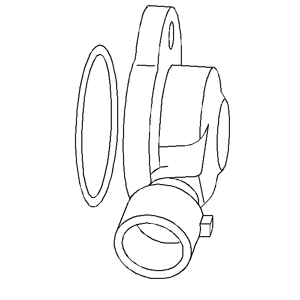
The nonadjustable TP sensor is mounted on the side of the throttle body opposite the throttle lever. It senses the throttle valve angle and relays that information to the PCM. Knowledge of the throttle angle is needed by the PCM to generate the required injector control signals (pulse). For further information, Refer to Information Sensors/Switches Description .
Mass Air Flow (MAF) Sensor
The MAF sensor is attached to the front (air inlet side) of the throttle body and is used to measure the amount of air entering the engine. The PCM uses this information to determine the operating condition of the engine and to control fuel delivery. For further information, refer to Information Sensors/Switches Description .
Fuel Pump Electrical Circuit
When the key is first turned ON, the PCM energizes the fuel pump relay for two seconds to build up the fuel pressure quickly. If the engine is not started within two seconds, the PCM shuts the fuel pump OFF and waits until the engine is cranked. When the engine is cranked and the RPM signal has been detected by the PCM, the PCM supplies 12 volts to the fuel pump relay to energize the electric in-tank fuel pump.
An inoperative fuel pump relay can result in long cranking times, particularly if the engine is cold.
An inoperative fuel pump would cause a no start condition. A fuel pump which does not provide enough pressure can result in poor performance.
Fuel Pump
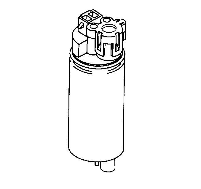
The fuel pump is mounted in the fuel reservoir within the modular fuel sender. The fuel pump is an electric high pressure gerotor pump. The fuel is pumped to the fuel rail at a specified flow and pressure. Excess fuel returns to the fuel tank by a return pipe. The fuel pump delivers a constant flow of fuel to the engine even during low fuel conditions and aggressive vehicle maneuvers. The electric fuel pump operation is controlled by the Powertrain Control Module (PCM) through a fuel pump relay. The fuel pump flex pipe acts to dampen the fuel pulses and noise generated by the fuel pump. The fuel pump is serviced as part of the Modular Fuel Sender Assembly.
Accelerator Controls
The accelerator control system is a cable-type. A specific accelerator control cable must be used, there is no linkage adjustments.
When work has been performed on the accelerator controls, always make sure that all components are installed correctly and that linkages and cables are not rubbing or binding in any manor. The throttle body should operate freely without binding between fully closed and wide open throttle.
7X Crankshaft Position (CKP) Sensor
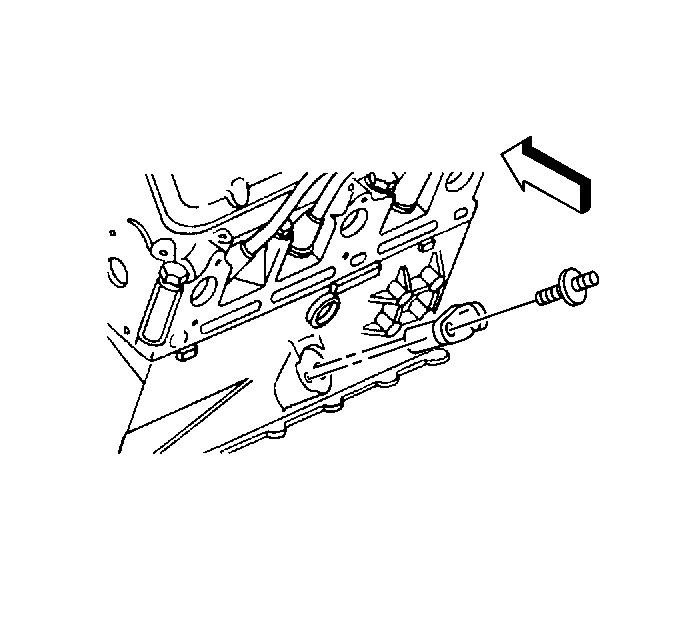
The ignition control module uses the 7X crankshaft position sensor to generate 3X reference pulses witch the PCM uses to calculate RPM and crankshaft position. The PCM uses the pulses to initiate injector pulses. if the PCM receives no pulses on this circuit, DTC P1374 will set and the PCM will use the 24X referance signal circuit for fuel and ignition control. For further information, refer to Information Sensors/Switches Description .
Camshaft Position (CMP) Sensor
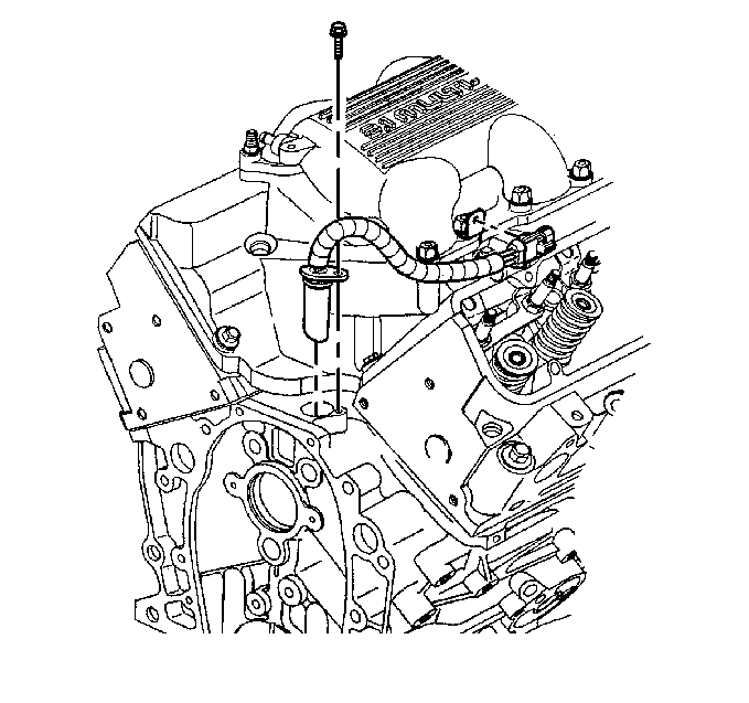
The CMP sends a cam signal to the PCM witch uses it as a sync pulse to trigger the fuel injectors in proper sequence. The PCM uses the cam signal to indicate the position of the #1 piston during its intake stroke. this allows the PCM to calculate true sequential fuel Injection (SFI) mode of operation. if the PCM detects an incorrect CAM signal while the engine is running, DTC P0341 will set. For further information, refer to Information Sensors/Switches Description .
