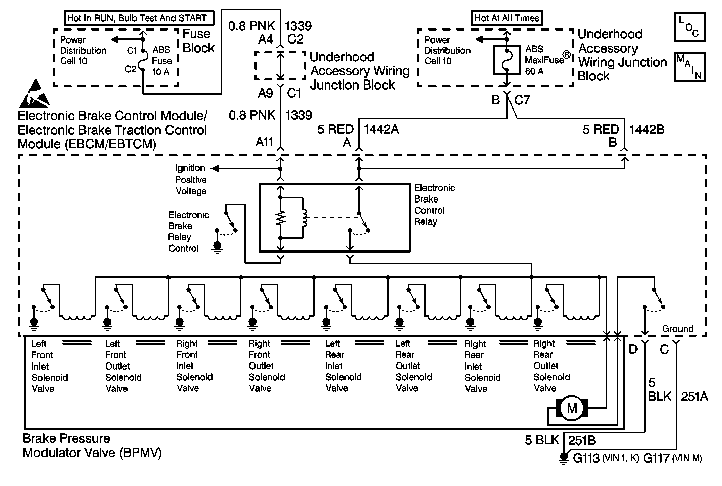
Circuit Description
When EBCM/EBTCM relay is activated (turned on) voltage is supply to valve solenoids and pump motor. This DTC identifies a malfunction with the EBCM/EBTCM loosing ground or battery, or when battery is disconnected while running.
Conditions for Setting the DTC
DTC C1254 is set when an running reset occurs. A running reset is when the vehicle is running and functions are normal then suddenly a loss of power or ground connection occurs to the EBCM/EBTCM.
Action Taken When the DTC Sets
| • | A malfunction DTC is stored. |
| • | ABS/TCS is disabled. |
| • | ABS/TCS Indicators are turned on. |
| • | Magnetic Steering Variable Assist (MSVA) is disabled. |
| • | TIM goes into Autolearn mode after system recovery. |
Conditions for Clearing the DTC
| • | Condition for DTC is no longer present and scan tool clear DTC function is used. |
| • | 100 ignition cycles have passed with no DTCs detected. |
Diagnostic Aids
| • | Possible causes for DTC C1254 to set are: |
| - | Running reset occurred. |
| - | Loss of EBCM/EBTCM ground. |
| - | Sudden drop in voltage. |
| - | Poor or loose grounds connections. |
| - | Poor or loose power connections. |
| - | Battery disconnected due to corrosion or loose battery terminals. |
| - | Internal EBCM/EBTCM malfunction. |
| • | It is very important that a thorough inspection of the wiring and connectors be performed. Failure to carefully and fully inspect wiring and connectors may result in misdiagnosis, causing part replacement with reappearance of the malfunction. |
| • | If an intermittent malfunction exists refer to Intermittents and Poor Connections Diagnosis in Wiring Systems. |
Step | Action | Value(s) | Yes | No | ||||||||||||||
|---|---|---|---|---|---|---|---|---|---|---|---|---|---|---|---|---|---|---|
1 | Was the Diagnostic System Check performed? | -- | ||||||||||||||||
2 |
Is the voltage within the range specified within the value(s) column? | 10.5-14.0 V | ||||||||||||||||
3 |
Is the voltage within the range specified within the value(s) column? | 10.5-14.0 V | ||||||||||||||||
4 |
Is the resistance within the range specified in the value(s) column? | 0 - 2 ohms | ||||||||||||||||
5 | Repair CKT 251A for an open or high resistance. Refer to Wiring Repairs in Wiring Systems. Is the repair complete? | -- | -- | |||||||||||||||
6 |
Is the resistance within the range specified in the value(s) column? | 0 - 2 ohms | ||||||||||||||||
7 | Repair CKT 251B for an open or high resistance. Refer to Wiring Repairs in Wiring Systems. Is the repair complete? | -- | -- | |||||||||||||||
8 |
Is the voltage within the range specified in the value(s) column? | 10.0-14.0 V | ||||||||||||||||
9 | Repair CKT 1339 for an open or high resistance. Refer to Wiring Repairs in Wiring Systems. Is the repair complete? | -- | -- | |||||||||||||||
10 |
Is the voltage within the range specified in the value(s) column? | 10.0-14.0 V | ||||||||||||||||
11 | Repair CKTs 1442A or 1142B for an open or high resistance. Refer to Wiring Repairs in Wiring Systems. Is the repair complete? | -- | -- | |||||||||||||||
12 |
Are there any signs of poor terminal contact, corrosion or damage terminal(s)? | -- | ||||||||||||||||
13 | Replace or repair all of the terminals and/or connectors that exhibit signs of poor terminal contact, corrosion or damage terminal(s). Is the repair complete? | -- | -- | |||||||||||||||
14 |
Does the Ignition Voltage and Switched Battery Voltage stay within the range specified in the value(s) column? | 10.0-14.0 V | ||||||||||||||||
15 | Repair the intermittent concern causing the Ignition Voltage or Switched Battery Voltage to drop below the specified value during cranking. Carefully inspect for the following:
| -- | -- | |||||||||||||||
16 |
Does the Ignition Voltage and Switched Battery Voltage stay within the range specified in the value(s) column? | 10.0-14.0 V | ||||||||||||||||
17 | Repair the intermittent concern causing the Ignition Voltage or Switched Battery Voltage to drop below the specified value during driving. Carefully inspect for the following:
| -- | -- | |||||||||||||||
18 | Replace the EBCM/EBTCM. Refer to Electronic Brake Control Module/Electronic Brake and Track Control Module Replacement . Is the replacement complete? | -- | -- |
