SERVICE MANUAL UPDATE SEC. 8A WIRING DIAGRAM AND DIAG. (A/C)

SUBJECT: SERVICE MANUAL UPDATE-SECTION 8A REVISED WIRING DIAGRAM AND DIAGNOSIS 8A-68 - AIR CONDITIONING
MODELS AFFECTED: 1991-92 ROADMASTERS
The 1991-92 Roadmaster Electrical Diagnosis Section 8A-68 is being revised to reflect corrected wiring diagrams and improved diagnosis procedures.
Any reference to "Early" or "Early Production" refers to 1992 Roadmaster Sedans built before NR421429. 8A-68 Section information for these vehicles can be found in the 1992 preliminary Roadmaster Sedan service manual or a reprint of selected 8A "Electrical Diagnosis" Sections for the "Early" Roadmaster Sedan.
Please insert the appropriate page(s) in your respective Roadmaster Service Manuals.
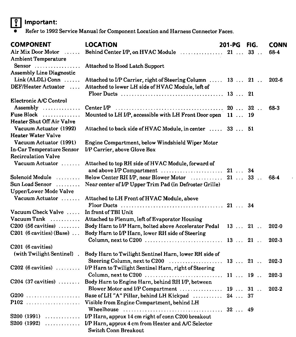
Important: --------- o Refer to 1992 Late Production Service Manual for Component Location and Harness Connector Faces.
COMPONENT LOCATION 201-PG FIG. CONN --------- -------- ------ ---- ---- Air Mix Door Motor Behind Center I/P, on HVAC Module 20 32 68-4
Ambient Temperature Sensor Attached to Hood Latch Support
Assembly Line Diagnostic Attached to I/P Link (ALDL) Conn Carrier, right of Steering Column 13 21 202-6
DEF/Heater Actuator Attached to lower LH side of HVAC Module, left of Floor Ducts 13 21
Electronic A/C Control Center I/P 18 29 68-3 Assembly
Fuse Block Mounted to LH I/P, accessible with LH Front Door open 11 19
Heater Shut-off Air Valve Attached to back Vacuum Actuator side of HVAC Module 35 56
Heater Water Valve Vacuum Actuator Attached to RH side (Early) of Plenum, forward of and above I/P Compartment
In-Car Temperature I/P Carrier, above Sensor Recirculation Glove Box Valve Vacuum Actuator Attached to top RH side of HVAC Module, forward of and above I/P Compartment 20 33
Solenoid Module Lower RH I/P, below Blower Motor 20 32 68-4
Sun Load Sensor Near center of I/P Upper Trim Pad (in Defroster Grille)
Upper/Lower Mode Valve Vacuum Actuator Attached to LH Front of HVAC Module, above Floor Ducts 20 33
Vacuum Check Valve In front of TBI Unit
Vacuum Tank Attached to Plenum, left of Evaporator Housing
C200 (56 cavities) Body Harn to I/P Harn, bolted to Bracket above Accelerator Pedal 13 21 202-0
C201 (6 cavities) Body Harn to I/P Harn, (Base) lower RH side of Steering Column, next to C200 13 21 202-3
C201 (6 cavities) (with Daytime Running Lights or Twilight Sentinel) Body Harn to Daytime Running Lights Harn or Twilight Sentinel Harn, lower RH side of Steering Column, next to C200 19 30 202-3
C202 (6 cavities) I/P Harn to Twilight Sentinel or Daytime Running Lights Harn, right of Steering Column, next to C200 11 19 202-3
C204 (37 cavities) Body Harn to Engine , Harn behind RH I/P, between Blower Motor and I/P Compartment 17 28 202-2
G200 Base of LH "A" Pillar, behind LH Kickpad 24 37
P101 RH I/P, right of ECM 20 33
P102 Visible from Engine Compartment, behind LH Wheelhouse 34 54
S200 (1991 and I/P Harn, approx 14 cm 1992 Early) right of conn C200 breakout
S200 (1992 Late) I/P Harn, approx 4 cm from Heater and A/C Selector Switch Conn breakout
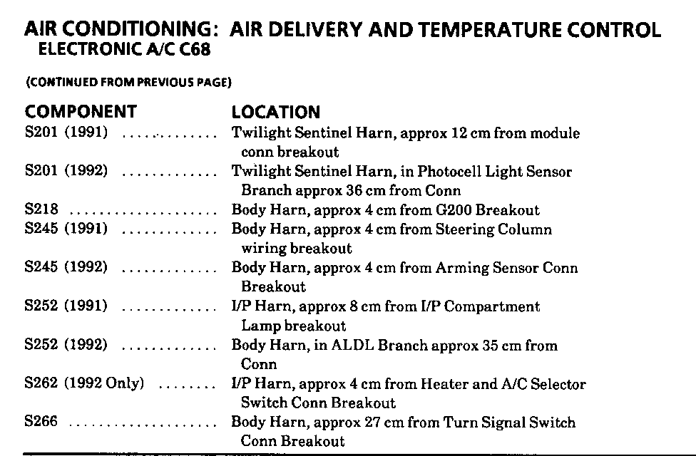
S201 (1991 and Twilight Sentinel or 1992 Early) Daytime Running Lights (DRL) Harn, approx 12 cm from module conn breakout
S201 (with Daytime Running Lights Lights) Harn, approx 15 cm from (1992 Late) Daytime Running Lights Dropping Diode Conn breakout
S201 (with Twilight Sentinel Harn, Sentinel) in Photocell Light Sensor (1992 Late) Branch approx 36 cm from Conn
S205 Daytime Running Lights Harn, approx 5 cm from Daytime Running Lights Dropping Diode Conn breakout
S218 Body Harn, approx 4 cm from G200 Breakout
S245 Body Harn, approx 4 cm from Steering Column wiring breakout
S252 I/P Harn, approx 8 cm from I/P Compartment Lamp breakout
S262 I/P Harn, approx 4 cm from Electronic A/C Control Head Conn breakout
S266 Body Harn, approx 27 cm from Turn/Hazard Switch Conn breakout
TROUBLESHOOTING HINTS
(Perform before beginning System Diagnosis)
1. If the Air Mix Door Motor is displaced from its proper position, it will automatically calibrate itself to the proper position if the Battery power is removed from the Electronic A/C Control Assembly. To recalibrate the Air Mix Door Motor, disconnect then reconnect the Battery.
2. If a low freon fault Code 9 is set, check for leaks in the system, repair as necessary, then recharge the A/C System. Reset the code by disconnecting and reconnecting the Battery or by pressing the "OFF" Touch Switch (while in the diagnostic mode). This will enable the A/C Compressor circuit to function if there is sufficient freon in the system.
3. Make sure that ground G200 is clean and tight.
4. Check Fuse 3 (1992 Late Production). If open, check for a short to ground in CKT 640 (Fuse 4 1991 and 1992 Early Production).
5. Check Fuse 6. If open, check for a short to ground in CKT 50.
6. Check for normal operation of Engine Vacuum Check Valve.
7. The Outside Air Temperature Display will not increase until vehicle is driven over 25 mph.
With Engine warm and running in idle:
8. Check manifold vacuum at the black hose from the Engine to the Vacuum Tank.
9. Check for vacuum at the violet hose from the Vacuum Tank to the Solenoid Module.
10. Check that the vacuum hoses from the Solenoid Module to the Vacuum Actuators are connected and in good condition.
o Refer to System Diagnosis.
SYSTEM DIAGNOSIS
o Diagnosis for the temperature control portion of this system is based on malfunction codes stored in the Electronic A/C Control Assembly. When a code has been set, the C (or F) indicator will flash. Refer to AUTOMATIC AIR CONDITIONING (SECTION 1C1 1991 and 1992 Early Production) or (SECTION 1C 1992 Late Production) for code diagnosis.
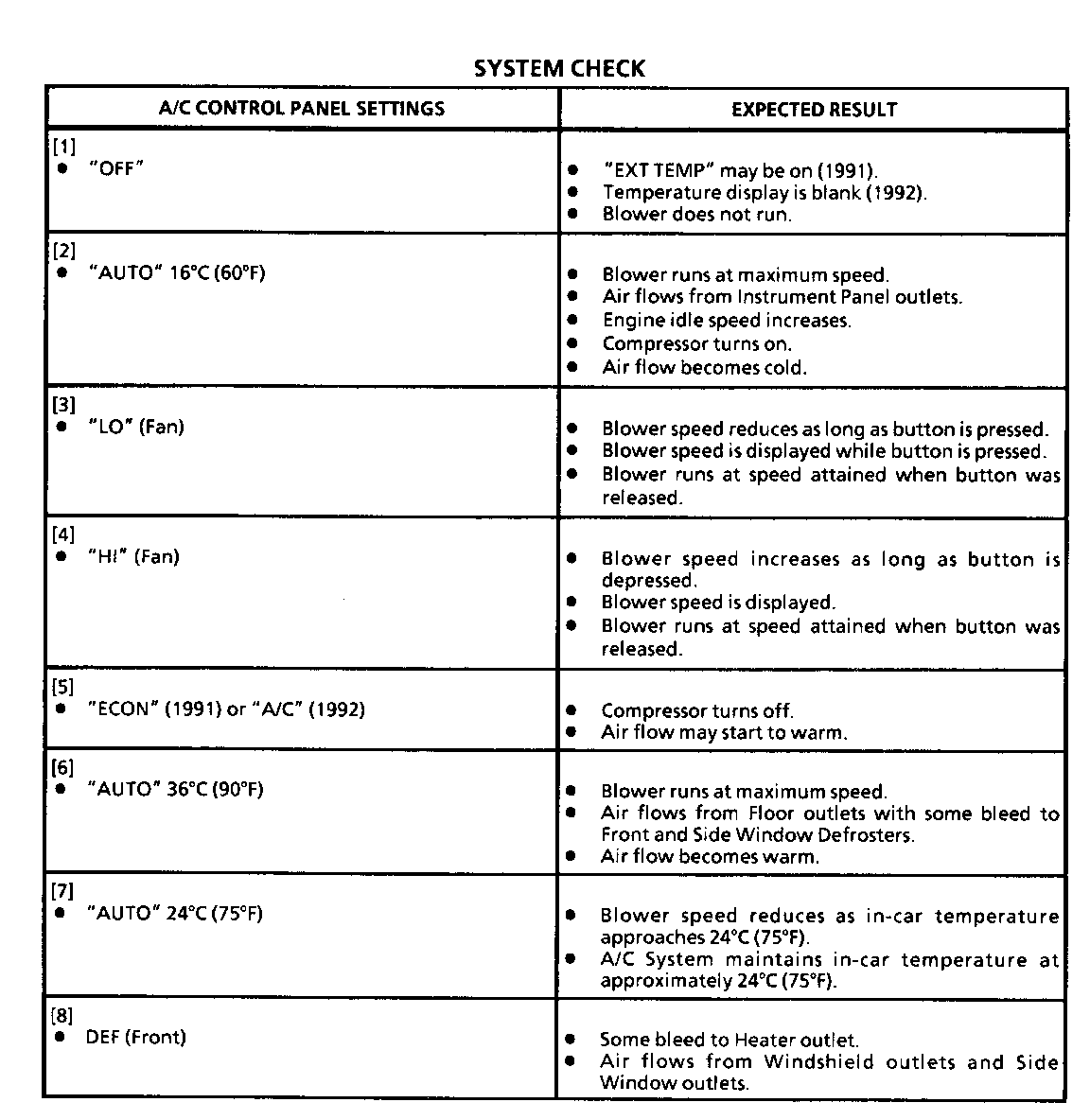
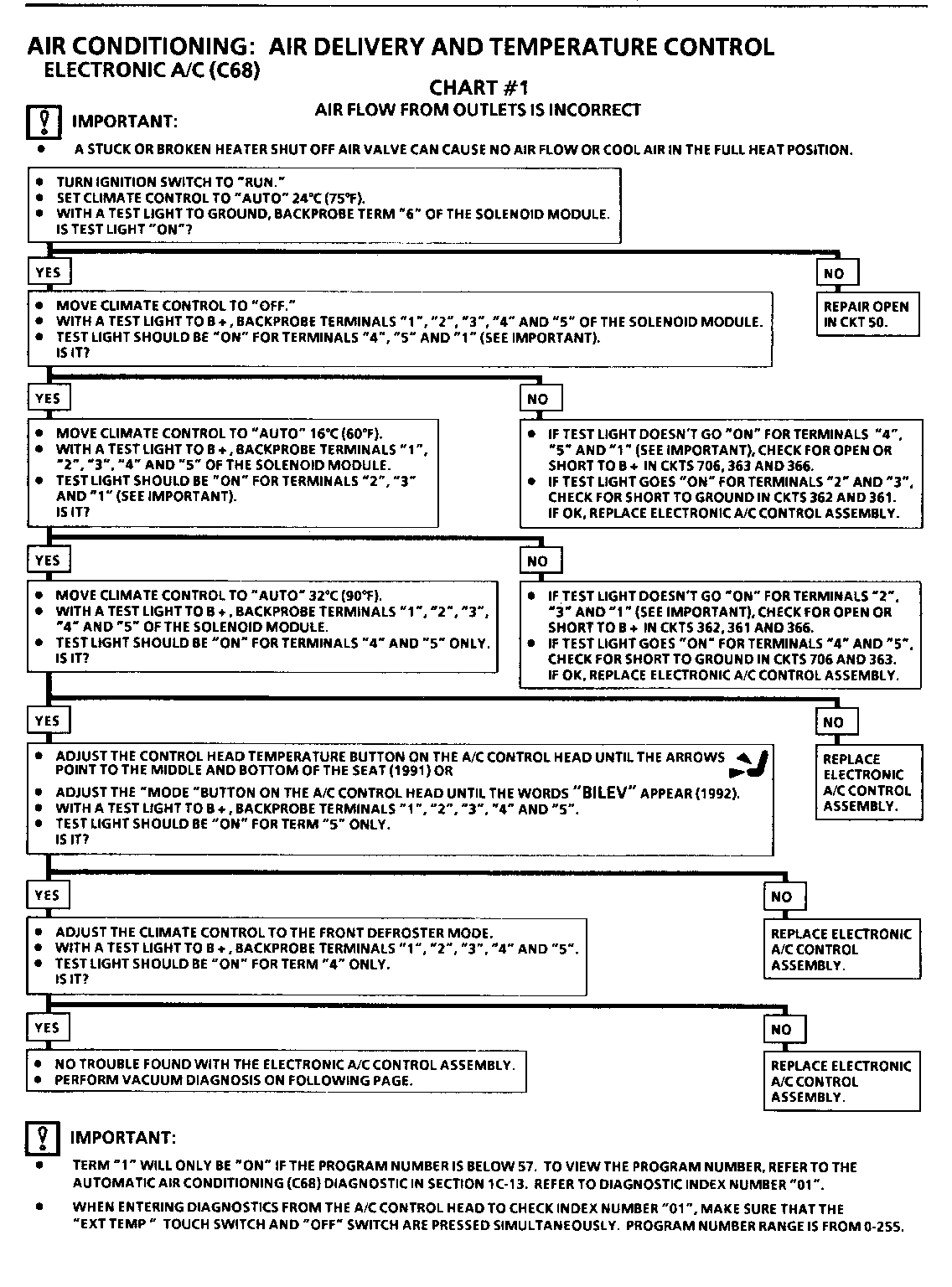
o If the air delivery appears incorrect, refer to System Check and perform Chart #1 on page 8A-68-8.
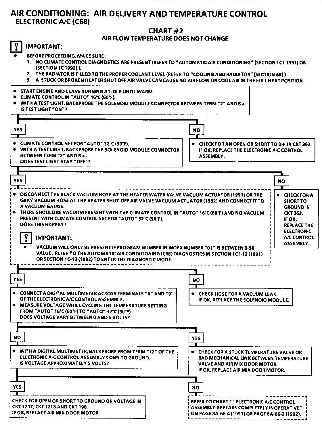
o If the temperature coming from the air ducts does not change when adjusting the temperature control button from 16C (60F) to 32C (90F), perform Chart #2 on page 8A-68-10.
SYSTEM CHECK
A/C CONTROL PANEL SETTINGS EXPECTED RESULT -------------------------- --------------- [1] "OFF" o Display is blank (1991 and (1992 Early Production). o "EXT TEMP" will display temperature (1992). o Blower does not run.
[2] "AUTO" 16C (60F) o Blower runs at maximum speed. o Air flows from instrument panel outlets. o Engine idle speed increases. o Compressor turns on. o Air flow becomes cold.
[3] "LO" (Fan) o Blower speed reduces as long as button is pressed. o Blower speed is displayed while button is pressed. o Blower runs at speed attained when button was released.
[4] "H" (Fan) o Blower speed increase as long as button is depressed. o Blower speed is displayed. o Blower runs at speed attained when button was released. [5] "ECON' o Compressor turns off. o Air flow may start to warm.
[6] "AUTO' 36C (90F) o Blower runs at maximum speed. o Air flows from Floor outlets with some bleed to Front and Side Window Defrosters. o Air flow becomes warm.
[7] "AUTO" 24C (75F) o Blower speed reduces as in-car temperature approaches 24C (75F). o A/C System maintains in-car temperature at approximately 24C (75F). [8] DEF (Front) o Some bleed to Heater outlet. o Air flows from Windshield outlets and Side Window outlets.
VACUUM DIAGNOSIS
Important: --------- To avoid misdiagnosis, perform Chart #1, "Air Flow From Outlets is Incorrect," before beginning Vacuum Diagnosis.
1. Check vacuum supply to Solenoid Module (black vacuum hose) while Engine is running.
o Vacuum should be approximately 55 kPa (16 psi) with Engine running.
o Vacuum should remain at approximately 55 kPa (16 psi) when Engine is turned off.
2. Test each vacuum actuator by disconnecting the vacuum hose and applying vacuum directly to the actuator. Repair or replace as necessary.
3. Reconnect all vacuum and electrical connections. Run Engine and cycle through the operating modes of the Electronic A/C Control Assembly while observing the vacuum actuators.
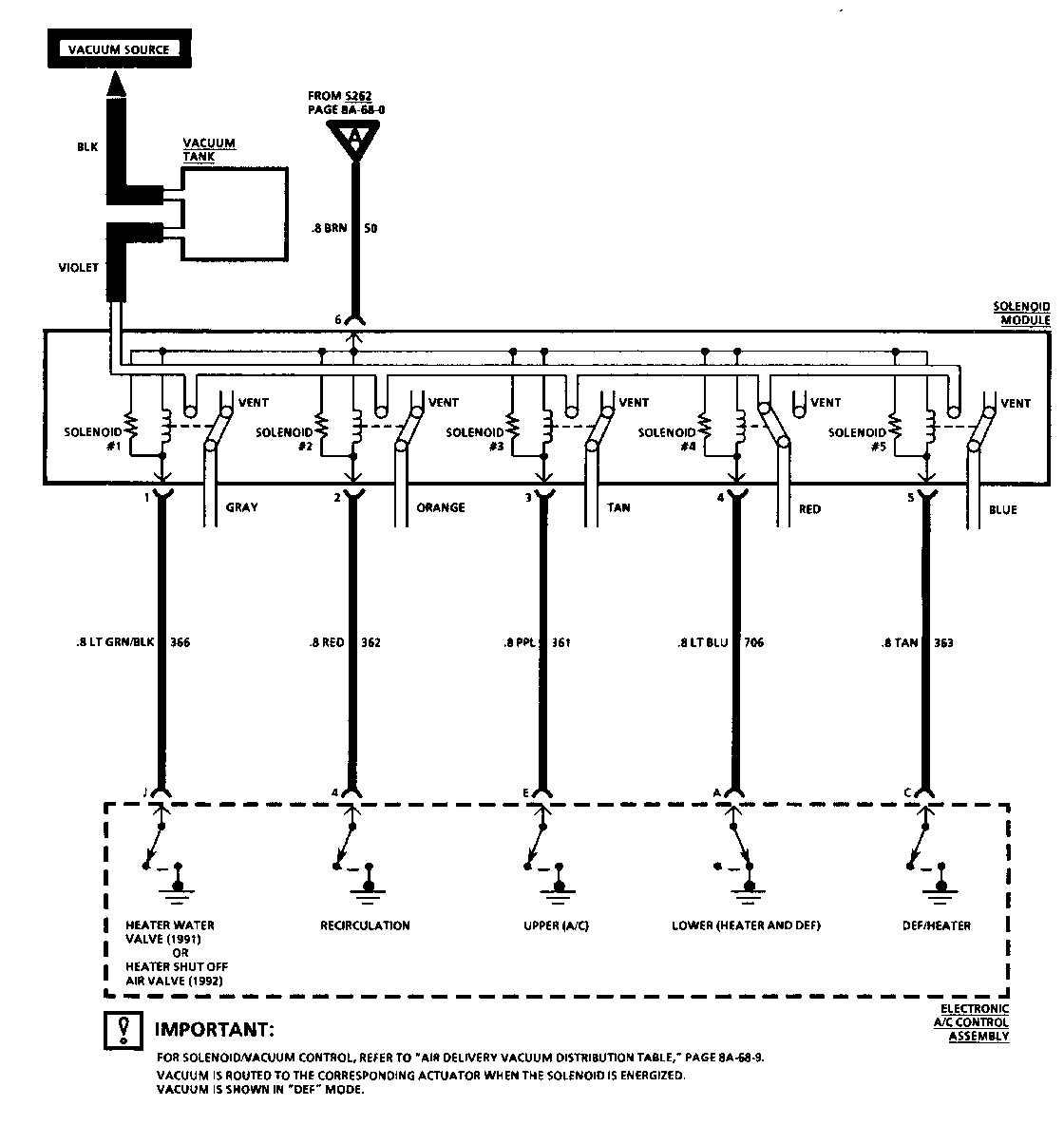
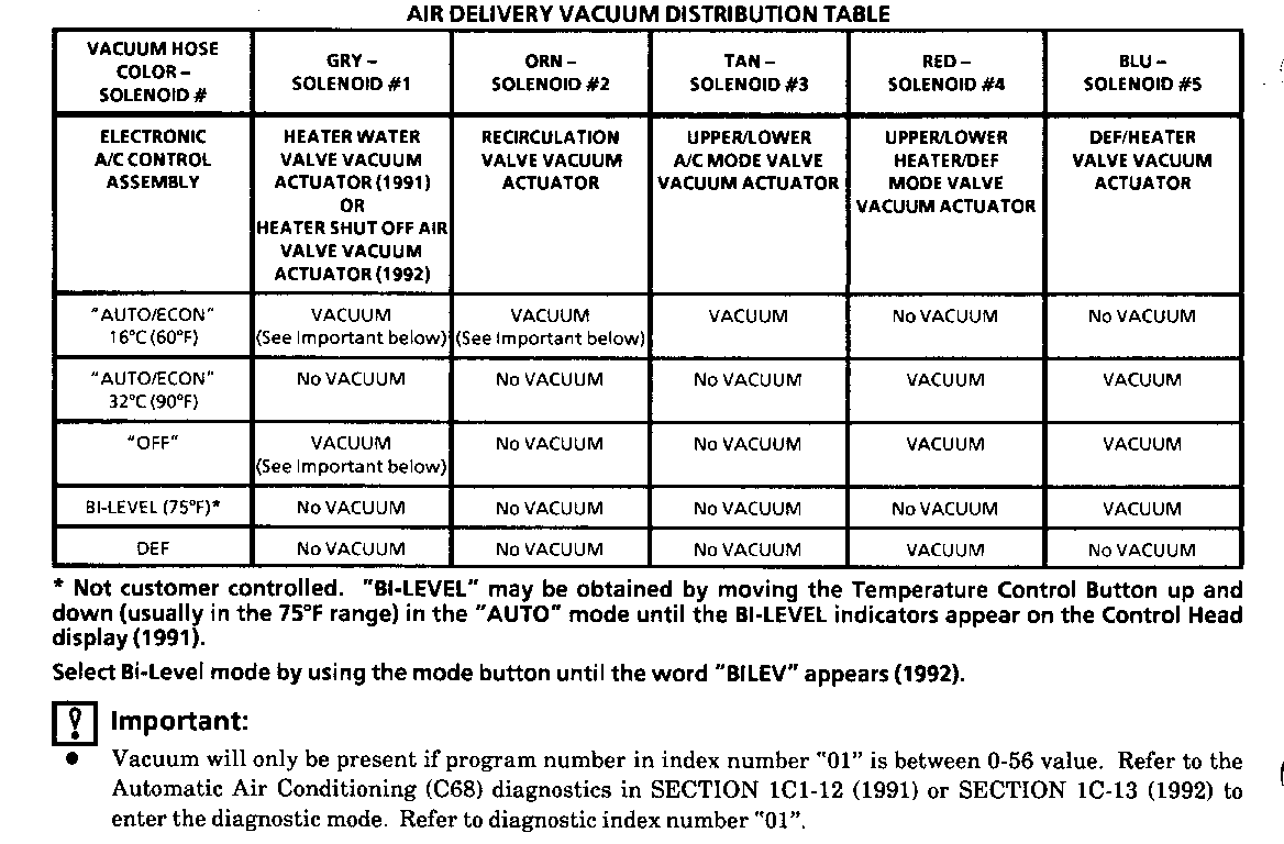
o Check for vacuum to the vacuum actuators by noting vacuum actuator position. When vacuum is applied, the actuator will retract, refer to Air Delivery Vacuum Distribution Table.
o If a vacuum actuator retracts when it should not, replace the Electronic A/C Control Assembly, after performing the diagnostics in Chart #1.
o If a vacuum actuator does not retract when it should, check for vacuum leaks, collapsed vacuum hoses, binding valves or bad connections at the Solenoid Module. If OK, replace the Solenoid Module.
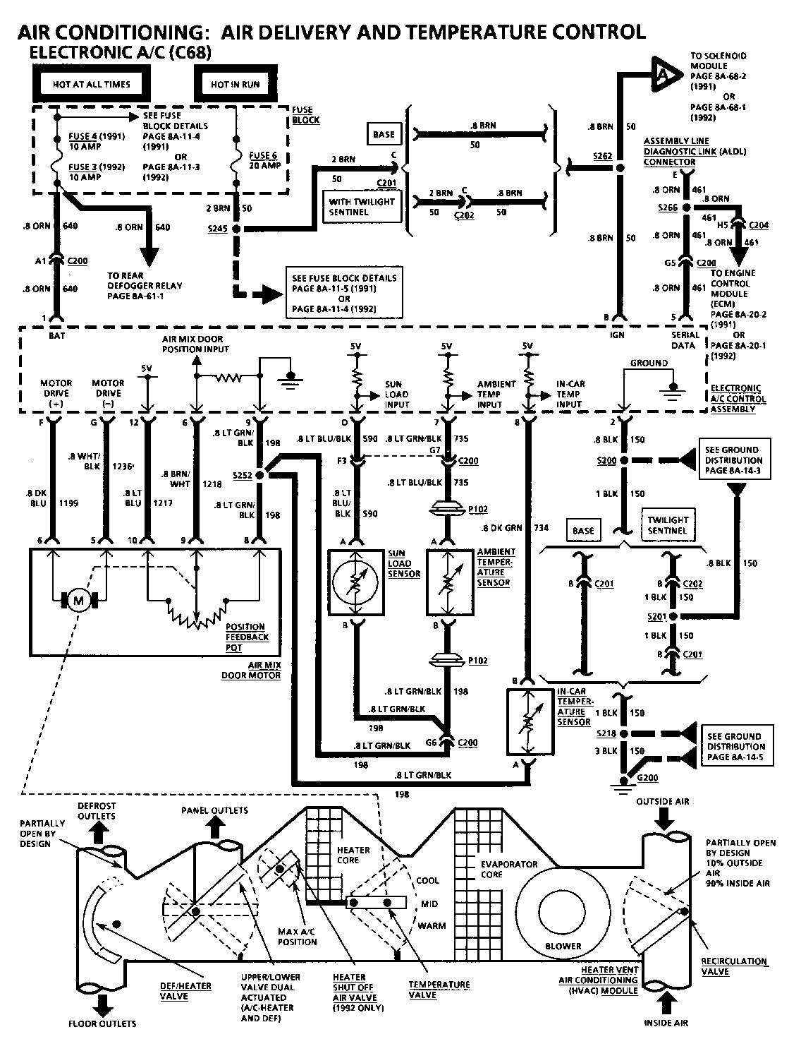
CIRCUIT OPERATION (AIR DELIVERY) ELECTRONIC A/C CONTROL ASSEMBLY ------------------------------- With the Ignition Switch in "RUN," voltage is applied through Fuse 6 to the Electronic A/C Control Assembly. The operating mode of the system is determined by buttons on the front panel. Ground signals determine which air valves are to be operated as well as the position of the Temperature Valve.
SOLENOID MODULE
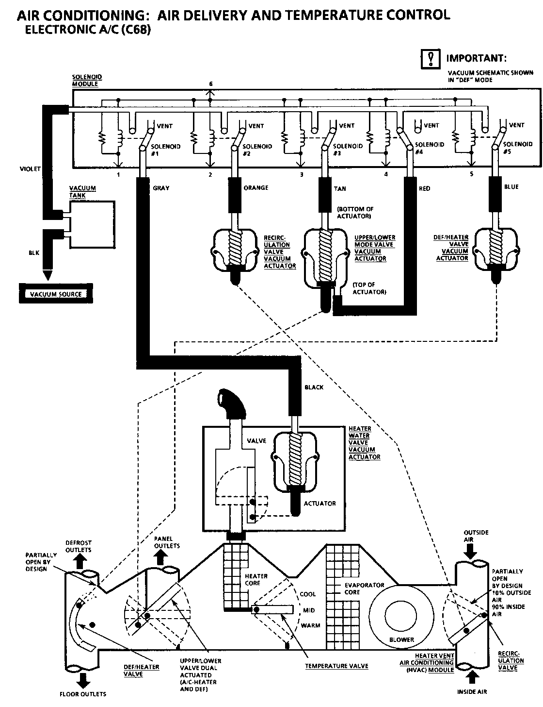
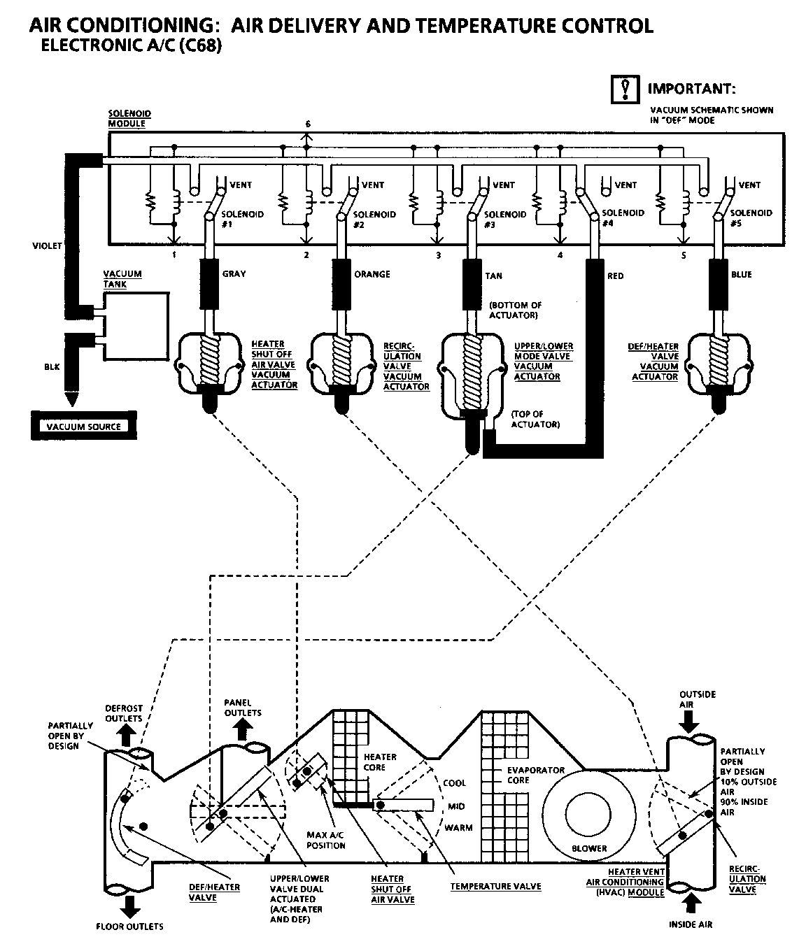
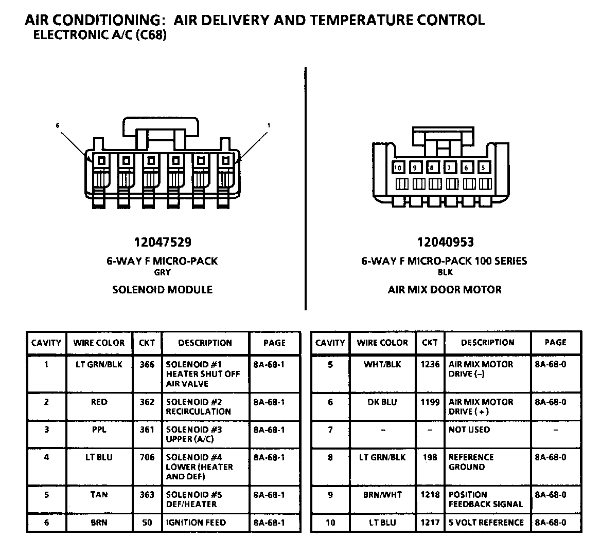
The Solenoid Module contains the solenoid valves that control the vacuum actuators. When the solenoids are de-energized, the valves vent the vacuum actuators, allowing the vacuum actuator to return to the Vent position.
RECIRCULATION VALVE
The Recirculation Valve closes off most of the outside air inlet so that the air from the inside of the vehicle is recirculated through the A/C System for maximum cooling. The outside air inlet is partially closed when vacuum is applied to the actuator. When the vacuum actuator is vented, the Recirculation Valves close off the in-car air inlet which allows outside air to be drawn into the vehicle.
TEMPERATURE VALVE
The Temperature Valve determines how much air flows through the Heater Core, which determines the temperature of the air to the outlets. It is moved by the Air Mix Door Motor. The position of the valve is determined by the temperature selected at the Electronic A/C Control Assembly.
DEF/HEATER ---------- The DEF/Heater Valve determines whether air flow will be directed to the windshield defrost outlets. With no vacuum applied to the actuator, the valve is positioned to allow air flow to the windshield defrost outlets, with some bleed to the heater outlet.
UPPER/LOWER MODE ---------------- The Upper/Lower Mode Valve can assume three positions and is operated by a bi-directional vacuum actuator which can move the valve to either of two positions. If no vacuum is applied to either vacuum actuator, the valve is in midposition. Air flow with the valve in midposition will be delivered to the panel outlets and the floor outlets (Bi-Level). When the Upper/Lower Solenoid (#3) (tan vacuum hose) is operated, the valve is positioned to direct air flow to the A/C outlets. When the Upper/Lower Solenoid (#4) (red vacuum hose) is operated, the valve is positioned to direct air flow to the heater outlets and defroster outlets.
HEATER WATER VALVE (1991 AND 1992 EARLY PRODUCTION) -------------------------------- The Heater Water Valve determines whether water will flow through the Heater Core or not. When the Heater Water Valve Vacuum Actuator is operated, the Heater Water Valve will close, stopping water flow into the Heater Core.
HEATER SHUT OFF AIR VALVE (1992 LATE PRODUCTION) ------------------------- The Heater Shut off Air Valve is used to block any air attempting to exit the Heater Core when temperature control is set to 16C (60-65 degrees), provided that program number in index number "01" is 0-56 (program number range is 0-255). Otherwise, it rotates out of the way so as not to block any air flow.
CIRCUIT OPERATION (TEMPERATURE CONTROL) --------------------- Three temperature variable resistors (sensors) are connected to the Electronic A/C Control Assembly to provide in-car and outside temperature information. These devices are thermistors which decrease in resistance as the temperature of the device increases. The one exception to this is the Solar Sensor, which is a Photo Diode. The Photo Diode output decreases with increasing light intensity. These sensors are connected to fixed resistors in the Control Assembly to provide a voltage input which varies according to the change in resistance. Ground reference for the sensors is provided by the Control Assembly.
Circuits within the Control Assembly use the input from the In-Car Sensor and the Sun Load Sensor and the set temperature selected by the driver to determine whether the air should be heated or cooled to bring the inside of the vehicle to the selected temperature. The input from the Ambient Temperature Sensor is used to determine the amount of heating or cooling required to bring the temperature inside the vehicle to the selected value as quickly as possible.
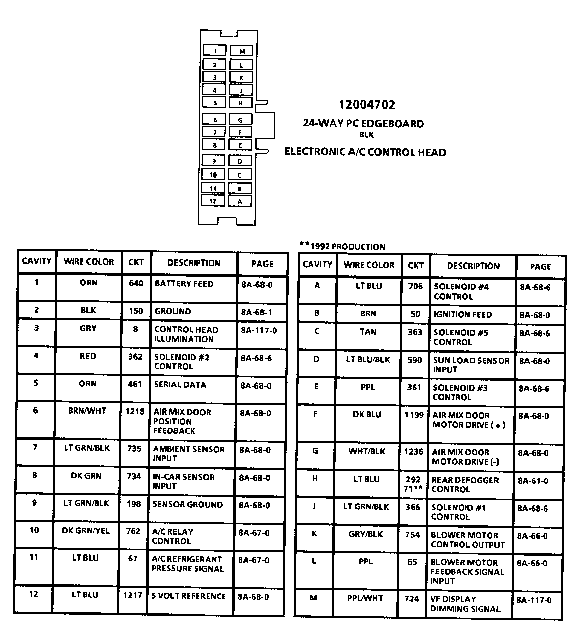
AIR CONDITIONING: AIR DELIVERY AND TEMPERATURE CONTROL ELECTRONIC A/C (C68) ------------------------------------------------------ The Air Mix Door Motor controls the position of the Temperature Valve. The motor can be operated in either direction by the polarity of the voltage applied to it. When the solid state switch grounds terminal "F" in the Electronic A/C Control Assembly, then terminal "5" of the Air Mix Door Motor is positive. If the condition of the solid state switches is reversed and terminal "G" is grounded, then terminal "6" of the Air Mix Door Motor is positive and the motor runs in the reverse direction.
The Position Feedback Pot indicates the position of the Temperature Valve at any point of its travel. As the Temperature Valve moves between fully open and fully closed, the voltage input at terminal "6" on the Electronic A/C Control Assembly will vary between .5 and 5 volts.
When a problem is detected with the temperature control system, certain malfunction codes may be set. A further description of these codes as well as diagnosis, will be found in SECTION 1C1-12 (1991 and 1992 Early Production) or SECTION 1C-12 (1992 Late Production).
General Motors bulletins are intended for use by professional technicians, not a "do-it-yourselfer". They are written to inform those technicians of conditions that may occur on some vehicles, or to provide information that could assist in the proper service of a vehicle. Properly trained technicians have the equipment, tools, safety instructions and know-how to do a job properly and safely. If a condition is described, do not assume that the bulletin applies to your vehicle, or that your vehicle will have that condition. See a General Motors dealer servicing your brand of General Motors vehicle for information on whether your vehicle may benefit from the information.
