STEERING WHEEL OSCILLATION/ VIBRATION(NEW STEERING DUMPER)

SUBJECT: STEERING WHEEL OSCILLATION/VIBRATION (NEW STEERING DAMPER)
VEHICLES AFFECTED: 1992 BUICK B-CAR WITH RPO NV7
CONDITION:
--------- Some 1992 B-car sedans with variable effort Power Steering (RPO NV7), may exhibit a slight steering wheel oscillation/vibration apparent when operated over irregular/rough road surfaces.
CAUSE:
----- Reduced power assist requirements result in greater road feel inputs being transmitted through the steering system.
CORRECTION:
---------- Install a steering damper and required attaching components noted below following service procedure indicated.
P/N PARTS REQUIRED QUANTITY --- PART DESCRIPTION -------- ----------------
10245794 Damper Frame Bracket 1 4993536 Steering Damper 1 26037685 Steering Relay Rod Kit 1 454947 Bolt 1 9422299 Nut 1
SERVICE PROCEDURE:
1. Disconnect battery.
2. Remove steering linkage relay rod following applicable Service Manual procedure in Section 3B3, "Steering Linkage".
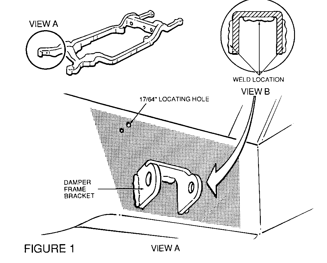
3. Referring to Figure 1, locate approximate area where damper bracket is to be welded to R.H. inner frame rail. Clean area with GM Tar and Road Oil Remover, P/N 1050172, or equivalent, insuring all dirt and wax coating is removed.
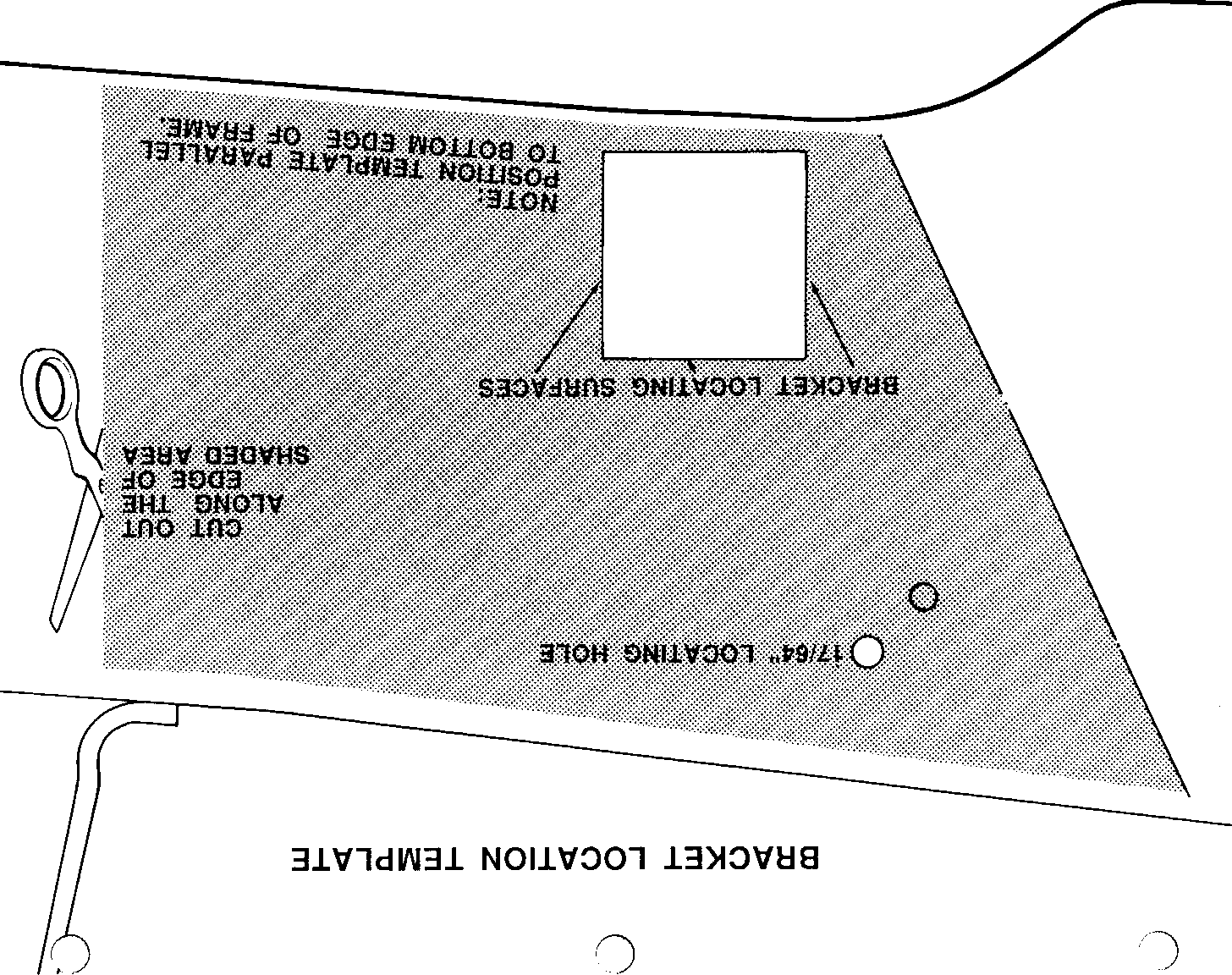
4. Position provided template on frame rail with a 17/64" drill bit inserted into hole in the frame and template. Rotate template so that bottom edge of template is parallel to the bottom edge of frame rail. Mark/scribe the location of the upper and two sides noted on the template as being the locating points for the bracket.
5. Secure and shield fuel lines upward and out of the way of the area where bracket is to be welded.
6. Position damper bracket onto frame rail and M.I.G. weld bracket to frame using American Welding Society Standard ER70S-6 wire and 75 percent argon 25 percent CO2 gas. Refer to Figure 1 for proper weld bead location.
NOTE: Only M.I.G welding is approved for this application. The welder must be properly grounded to the front suspension crossmember of the frame. Grounding to any bolted on part is not approved.
7. Apply GM Anti-Corrosion Compound, P/N 12345489 (16 oz. aerosol can) or equivalent to frame and bracket, insuring all bare metal surfaces are covered.
8. Remove shielding utilized to protect fuel lines and position fuel lines in original location.
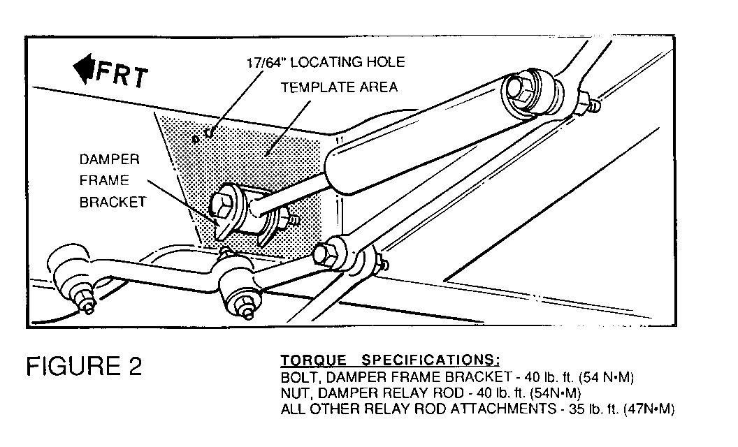
9. Install steering relay rod and steering damper following applicable Service Manual procedures in Section 3B3, "Steering Linkage", and those noted in Figure 2.
Torque Specifications:
Bolt, Damper Frame Bracket 54 N.m (40 lb. ft.) Nut, Damper Relay Rod 54 N.m (40 lb. ft.) All Other Relay Rod Attachments 47 N.m (35 lb. ft.)
10. Reconnect battery.
Warranty Information:
For vehicles repaired under warranty use:
Labour Time: 1.7 Hours


General Motors bulletins are intended for use by professional technicians, not a "do-it-yourselfer". They are written to inform those technicians of conditions that may occur on some vehicles, or to provide information that could assist in the proper service of a vehicle. Properly trained technicians have the equipment, tools, safety instructions and know-how to do a job properly and safely. If a condition is described, do not assume that the bulletin applies to your vehicle, or that your vehicle will have that condition. See a General Motors dealer servicing your brand of General Motors vehicle for information on whether your vehicle may benefit from the information.
