INTAKE VALVE SEALS REWORK INFORMATION

VEHICLES AFFECTED: All Vehicles Equipped with the Buick 3.0L, 3.8L, and 4.1L V-6 Engines, (Codes A, E, 4, 8, 3)
This bulletin supercedes all information contained in 1983 PSB 6-135 dated Feb. 28/83.
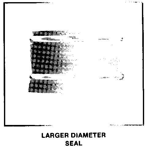
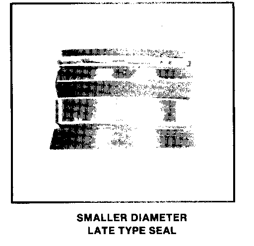
A new smaller diameter intake valve seal went into production approximately December 1, 1982, on the 3.0L, 3.8L, and 4.1L engines (See Illustration). The new seal will reduce the possibility of the seals lifting off the valve guide, which could result in abnormal oil consumption or detonation.
If either of these conditions is encountered, the new seals, Part No. 25518390, should be installed. The seals should also be installed on the above engines whenever engine coolant (ethylene glycol) which can deteriorate the valve seal is present in the engine oil or internal coolant loss is suspected. Since the cylinder head valve guide outside diameter was reduced to accept the new seal, it will be necessary to rework the valve guide to the new smaller diameter prior to its installation.
This can be done by removing the cylinder head and using a valve guide cutting tool such as the Hastings 1758 or equivalent, which will reduce the valve guide outside diameter to the new dimension, and is available from the foliowing address:
Hastings Inc. 390 Birchmount Rd. Scarborough, ON M1K 1M8 (416) 698-7161
INSTRUCTIONS FOR MACHINING GUIDES
1. Remove cylinder head and valve assemblies as outlined in the Service Manual.
2. Remove both intake and exhaust valves from cylinder head. (This is necessary to eliminate possibility of metal chips from cutting tool becoming lodged in exhaust valve guide mechanism.)
3. Insert machining tool in chuck of 1/2 inch electric drill (low speed drill).
4. Place cylinder head on clean working surface, oil tool pilot and insert it into intake valve guide.
5. Apply steady pressure to cutting tool. Machine valve guide until small cutter block in tool has cut chamfer on top of valve guide.
6. Thoroughly clean cylinder heads and guides, removing any cuttings and carbon buildup.
7. Remove any burrs from valve stems and guides with a fine stone or crocus cloth. At this point, valve guides sould be checked for concentricity; valve guide opening centered in valve guide, and that there is sufficient stock left around the circumference of the valve guide to properly retain valve seals.
8. Remove excess carbon from valves, oil valves and insert them into valve guides.
9. Install new seals on intake valves and over valve guides using a deep well socket to ensure seal is on squarely and firmly seated.
10. Reassemble balance of cylinder head assembly - reinstall on engine.
WARRANTY INFORMATION
LABOUR OPERATION
Use published labour operation to R & R cylinder head gasket(s).
TIME ALLOWANCE
Use published time, plus add time of:
0.5 hr. for one cylinder head 0.9 hr. for both cylinder heads
For your information, Service Part Number for the new cylinder head is 25516366.


General Motors bulletins are intended for use by professional technicians, not a "do-it-yourselfer". They are written to inform those technicians of conditions that may occur on some vehicles, or to provide information that could assist in the proper service of a vehicle. Properly trained technicians have the equipment, tools, safety instructions and know-how to do a job properly and safely. If a condition is described, do not assume that the bulletin applies to your vehicle, or that your vehicle will have that condition. See a General Motors dealer servicing your brand of General Motors vehicle for information on whether your vehicle may benefit from the information.
