POWERMASTER BRAKE ASSEMBLY EXCHANGE PROGRAM

Models Affected: 1985 Regal "T" Type Models (SFI Turbo Engines VIN Code 9)
This bulletin supersedes Bulletin 85-5-5 dated April, 1985. Please discard original and replace it with this one.
The Powermaster Brake System went into production during the week of March 4, 1985 on the above models (refer to Section 5D4 in the 1985 Buick Chassis Service Manual).
To obtain information on early 1985 Powermaster Brake Systems, a Powermaster service exchange program has been established.
If a Powermaster unit should require replacement, or any component of the unit to correct the problem, a replacement unit will be furnished "no charge" by Buick in exchange for the unit. The furnished unit is complete and may be directly installed on the vehicle.
Only Powermasters which have not been disassembled are included in this exchange program. No other service parts program has been established at this time for the Powermaster assembly.
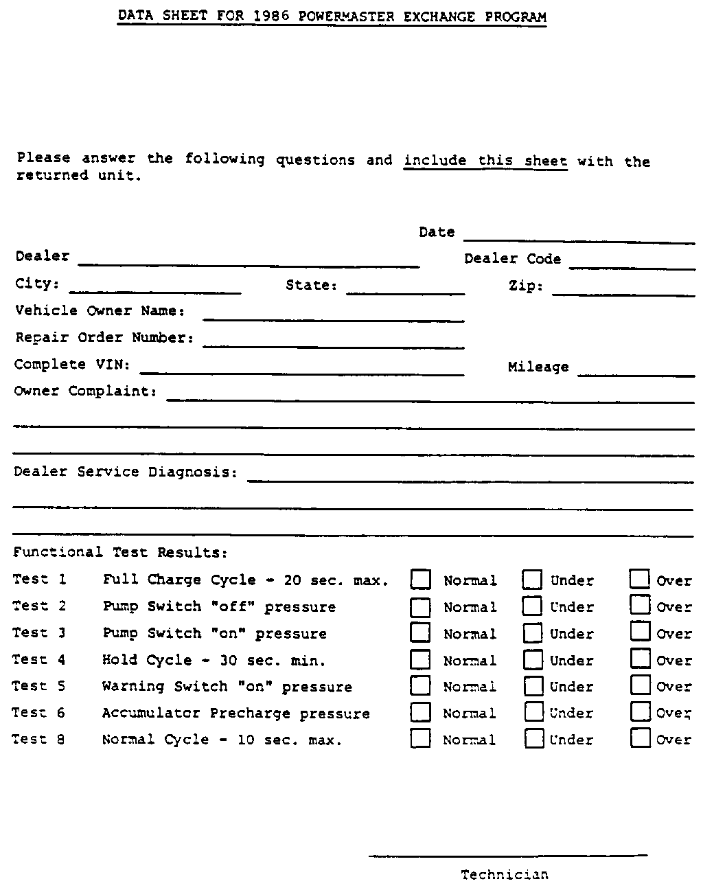
Exchange Powermaster Assemblies can be obtained by contacting the Buick Technical Assistance Center in Flint, Michigan. * Also included on page 3 of this bulletin is a copy of the instruction data sheet which is furnished with an exchange unit. It is important the functional test results be recorded prior to removal of the original powermaster assembly from a vehicle so that the functional test results can be listed on the data sheet when it is returned to Delco with the replaced unit.
PRELIMINARY EVALUATION TO DETERMINE NEED FOR EXCHANGE
The following outline indicates preliminary checks required to diagnose a Powermaster to determine the need for an exchange unit.
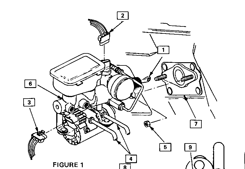
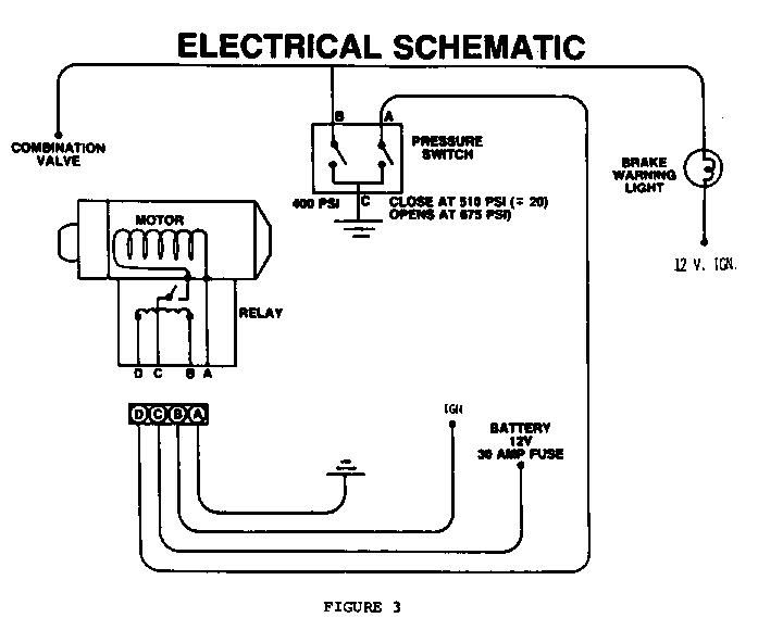
1) Verify electrical power to the Powermaster unit and the presence of proper ground circuits (Refer to Figure 1 and pages 144 and 145 in the 1985 Chassis Service Manual in "C' Electrical Diagnosis).
2) Verify the proper brake fluid levels in the Powermaster reservoir. (Accumulator fully depressurized).
3) Install J-35126 test gage adapter and perform 1985 Chassis Service Manual Functional Check and Diagnostic Procedure (page 5D4-7,8 and 9).
The acceptable values for the Functional Check (item 3 above) are:
Time to charge from 0 psi to
Pump switch "off" - 20 seconds max. - Sequence #1
Pump switch "off' pressure - 635 to 735 psi (4.378-5.068 kPa) - Sequence #2
**Pump switch "on" pressure - 490 to 530 psi (3.378-3.654 kPa) - Sequence #3
Time between pump cycles with
"steady brake apply & hold" - 30 seconds min. - Sequence #4
WARNING
switch" on pressure - 355 to 435 psi (2.448-2.999 kPa) - Seq. #5
*Accumulator precharge pressure - 200 to 330 psi (1.379-2.275 kPa) Seq. #6
Time to charge between Pump switch "on/off" - 10 seconds max. (Sequence #8)
* Fluid temperature in accumulator at 60-80 DEG F (16-27 DEG C).
If functional check procedures do not at this time show cause for unit removal, continue diagnosis for leaks, poor brake bleed, poor brake adjustment, pump noise (excessive). Adjust and repair all faults external to Powermaster before requesting an exchange unit.
POWERMASTER SERVICE EXCHANGE UNIT PACKAGE
The service exchange package contains the following:
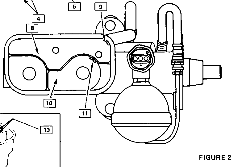
1 - Powermaster exchange unit - (Items 17 and 44 shown in Figure 2.) 1 - Pre-addressed return shipping label (Shown below). 1 - Information data sheet. 1 - Instruction sheet.
The replaced (original) Powermaster Unit is to be carefully packaged in the container the new unit was received in; data sheet ccmpletely filled out and shipped by U.P.S. to the following address using furnished label:
Delco Moraine Division Cincinnati Street - Dock 4 Dayton, Ohio 45408
Attn: Reliability Lab
* Added ** Revised
BUICK MOTOR DIVISION Service Department Flint, Michigan
DATA SHEET FOR 1985 POWERMASTER EXCHANGE PROGRAM
This Powermaster is furnished "no charge" for use on a special replacement program. In returning the defective unit, please use the enclosed shipping label to insure proper handling and quick analysis.
Please answer the following questions and include this sheet with the returned unit.
Date____________________ Dealer Dealer Code_____________ City: State: Zip:_____________________
Vehicle Owner Name:
Repair Order Number: Complete VIN: Mileage Owner Complaint:
Dealer Service Diagnosis:
Functional Test Results:
Test 1 Full Charge Cycle - 20 sec. max. Normal Under Over Test 2 Pump Switch "off" pressure Normal Under Over Test 3 Pump Switch "on" pressure Normal Under Over Test 4 Hold Cycle - 30 sec. min. Normal Under Over Test 5 Warning Switch "on" pressure Normal Under Over Tect 6 Accumulator Precharge pressure Normal Under Over Test 8 Normal Cycle - 10 sec. max. Normal Under Over
General Motors bulletins are intended for use by professional technicians, not a "do-it-yourselfer". They are written to inform those technicians of conditions that may occur on some vehicles, or to provide information that could assist in the proper service of a vehicle. Properly trained technicians have the equipment, tools, safety instructions and know-how to do a job properly and safely. If a condition is described, do not assume that the bulletin applies to your vehicle, or that your vehicle will have that condition. See a General Motors dealer servicing your brand of General Motors vehicle for information on whether your vehicle may benefit from the information.
