SERVICE MANUAL REVISION CHART A-3 AND C4 SECTION 6E

VEHICLES AFFECTED: 1985-88 A,C,E,H,N,G W/3.8 3.0
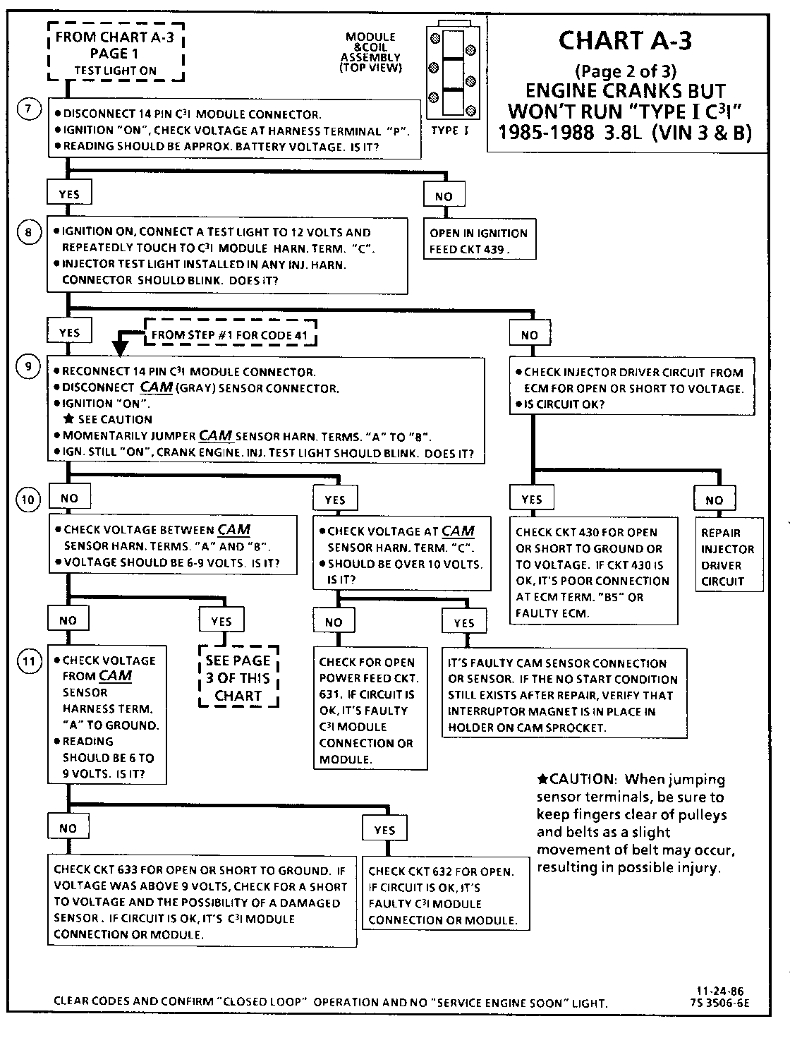
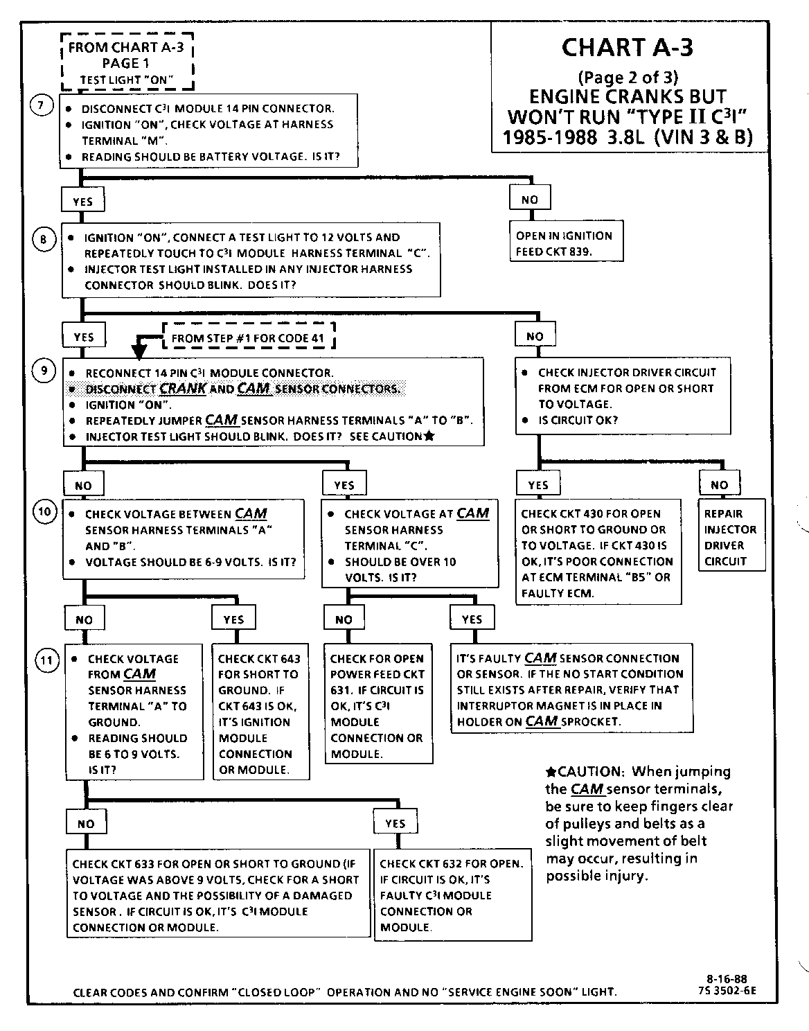
* This bulletin has been revised to clarify Step 9. Revision to Chart A-3 (page 2 of 3) - Step 9 of P.S.B. 87-630-107 and 87-638-111, Page 11. The revision in Step 9 is required to make the chart work properly. If the crank sensor is indexed so that a window is in front of the hall switch, the crank signal will be pulled low and the injector test light will not flash.
These revisions are presented to clarify the diagnostic procedure for the C"3"I ignition system. These charts supercede the A-3 charts and C-4 charts in the 1986 and 1987 service manuals for the engines listed above.
This revision is presented to clarify Chart C-4 for 1986-87 A, C, and H carlines equipped with 3.8L (VIN 3 and B) engines. This revision replaces the appropriate page in the service bulletin. Step 4 has been revised to include Type II ignition system check.
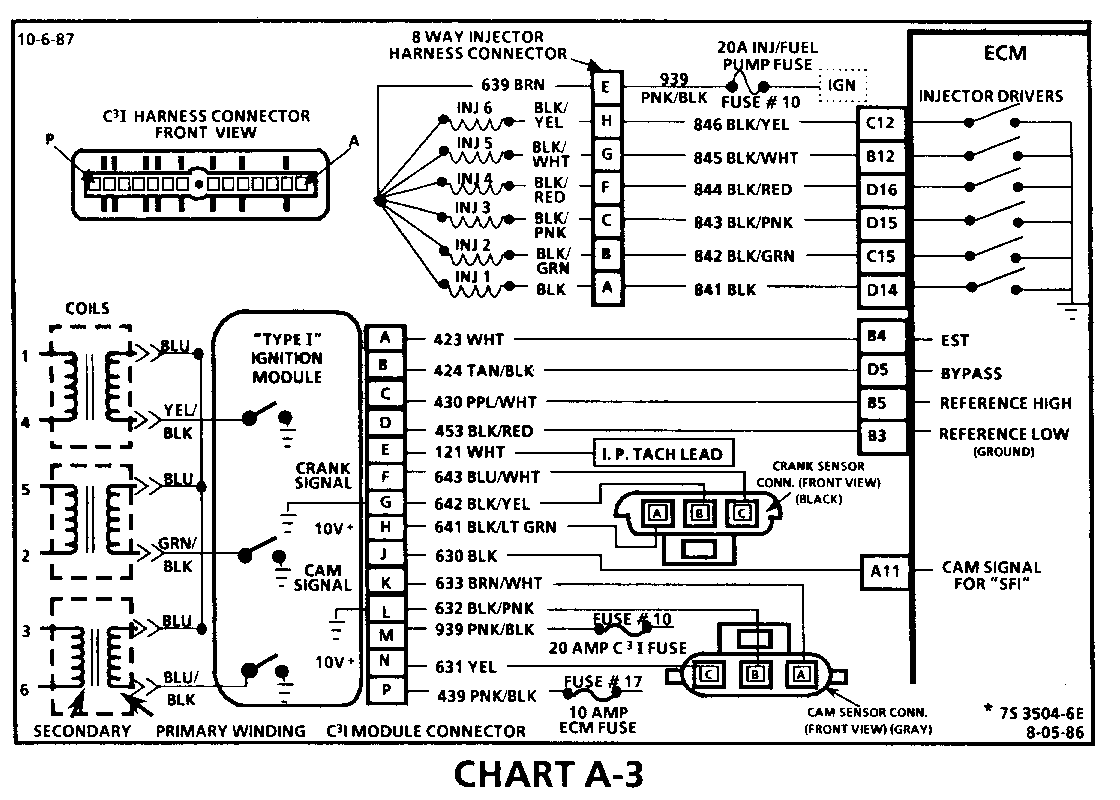
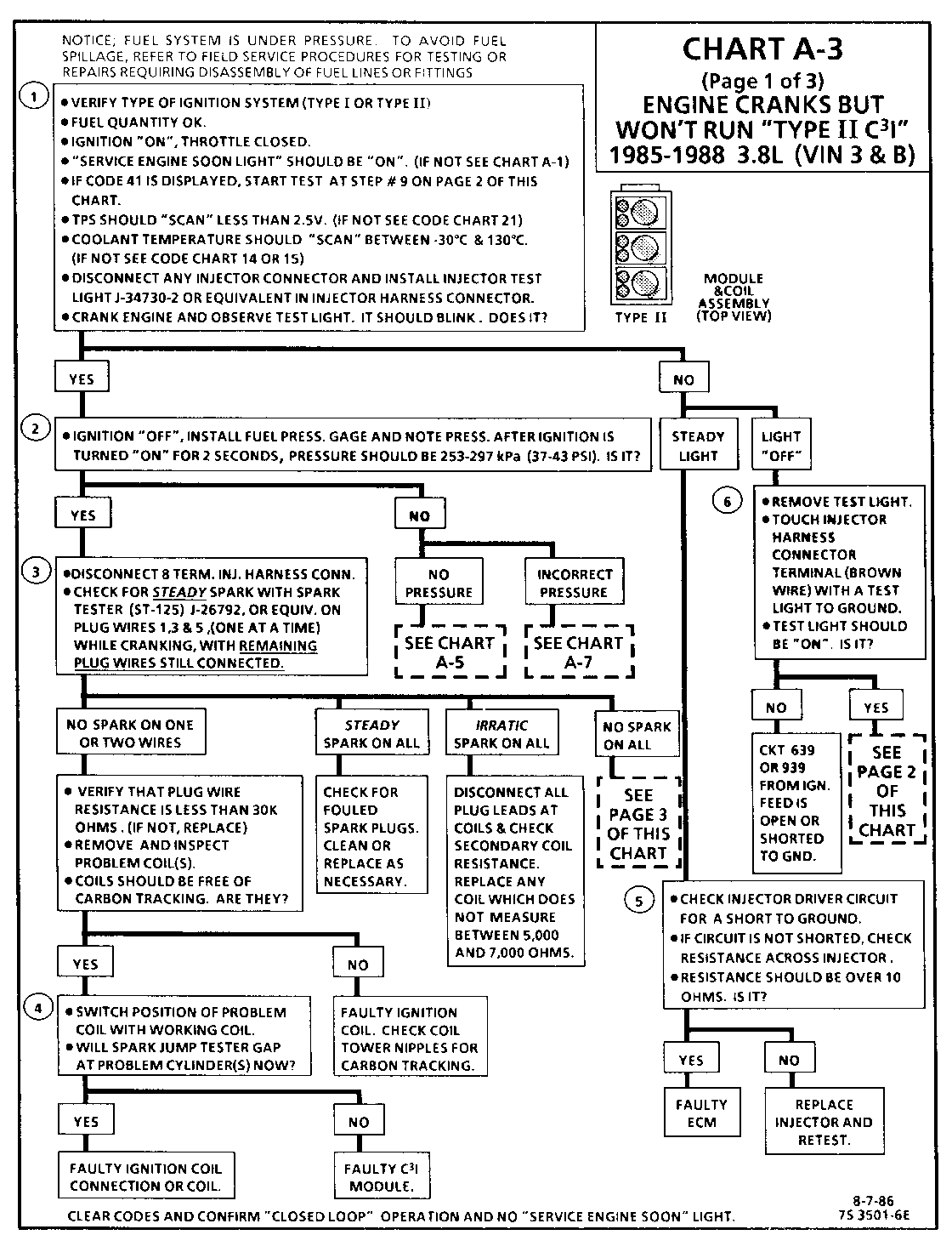
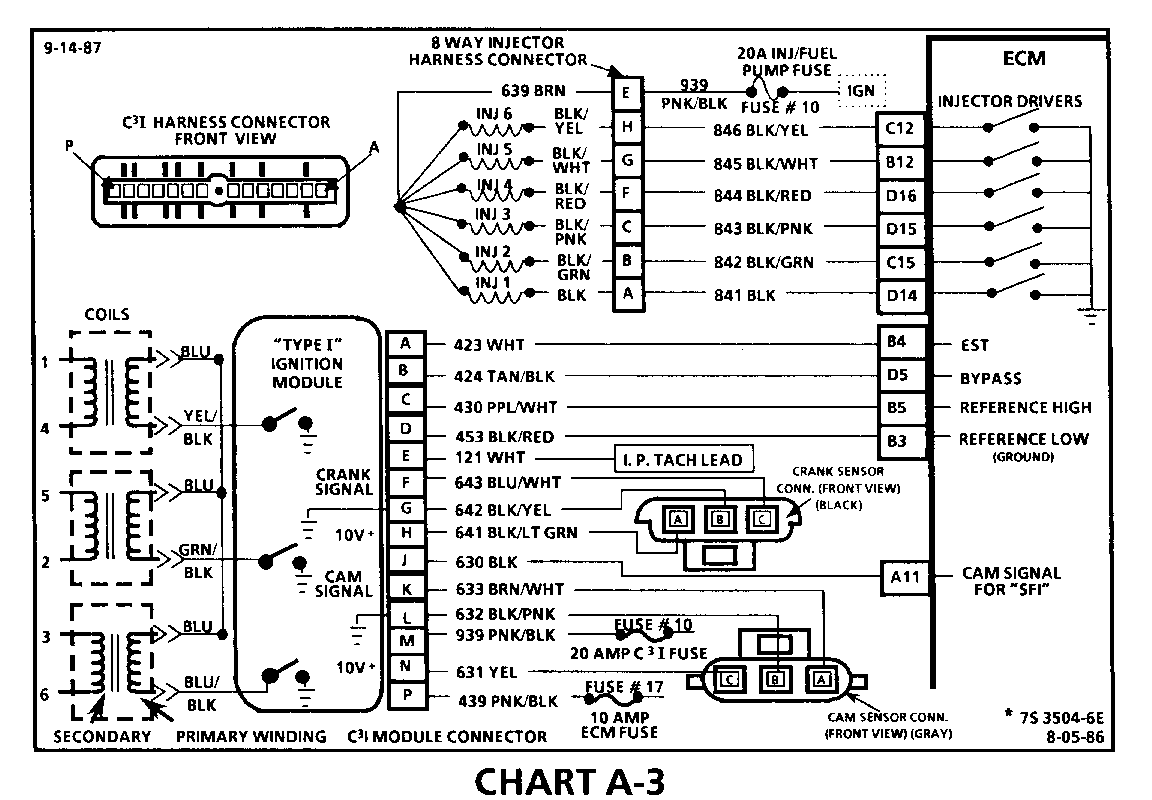
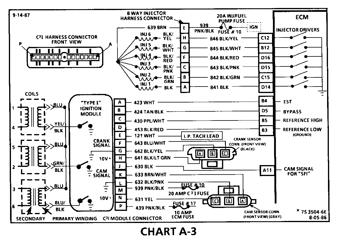
CHART A-3 (Page 2 of 3) ENGINE CRANKS BUT WON'T RUN "TYPE I C31" 1986-1987 3.8L (VIN 3 & B)
Circuit Description:
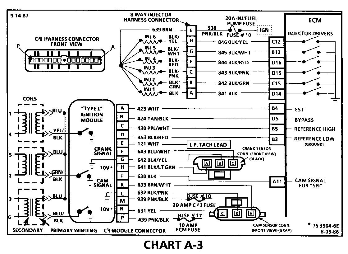
For timing of spark plug firing, a cam sensor "hall effect" switch is used. The cam sensor sends a signal (Sync-Pulse) to the ignition module when cylinder #1 is 25 DEG after top dead center on the compression stroke. This signal is used to start the correct coil firing sequence and to enable sequential fuel injection. The engine will continue to run if the cam signal to the ignition module (CKT 633) is lost, however, will not restart after shut down and a Code 41 will be stored.
The crank sensor sends a signal to the ignition module and then to the ECM for reference rpm and crankshaft position. There are three windows in a disc (interruptor) which is mounted to the harmonic balancer. As these windows pass by the sensor, the next ignition coil is triggered.
Test Description: Numbers below refer to circled numbers on the diagnostic chart.
7. Verifies ignition feed voltage at terminal "P" of the C3I module. Less than battery voltage would be an indication of a CKT 439 fault.
8. The test light to 12 volts simulates a reference signal to the ECM which will result in an injector test light blink. This test validates CKT 430, the ECM and the injector driver circuits.
9. If the Cam Sensor signal circuit terminal "A" is momentarily jumpered to the ground circuit terminal "B" and the engine is cranked, without turning the ignition switch "OFF", the response should be an injector test light blink. This is a result of the artificial "Cam Signal" being transmitted through the C31 module to ECM terminal "All" and the ECM activating the injector driver circuit.
10. Verifies a proper Cam signal circuit voltage of 6 to 9 volts and a good ground from the C3I module to terminal "B" of the sensor connector.
11. Determines if incorrect voltage reading was due to a fault in CKT 633, an open in CKT 632 or a faulty C3I module.
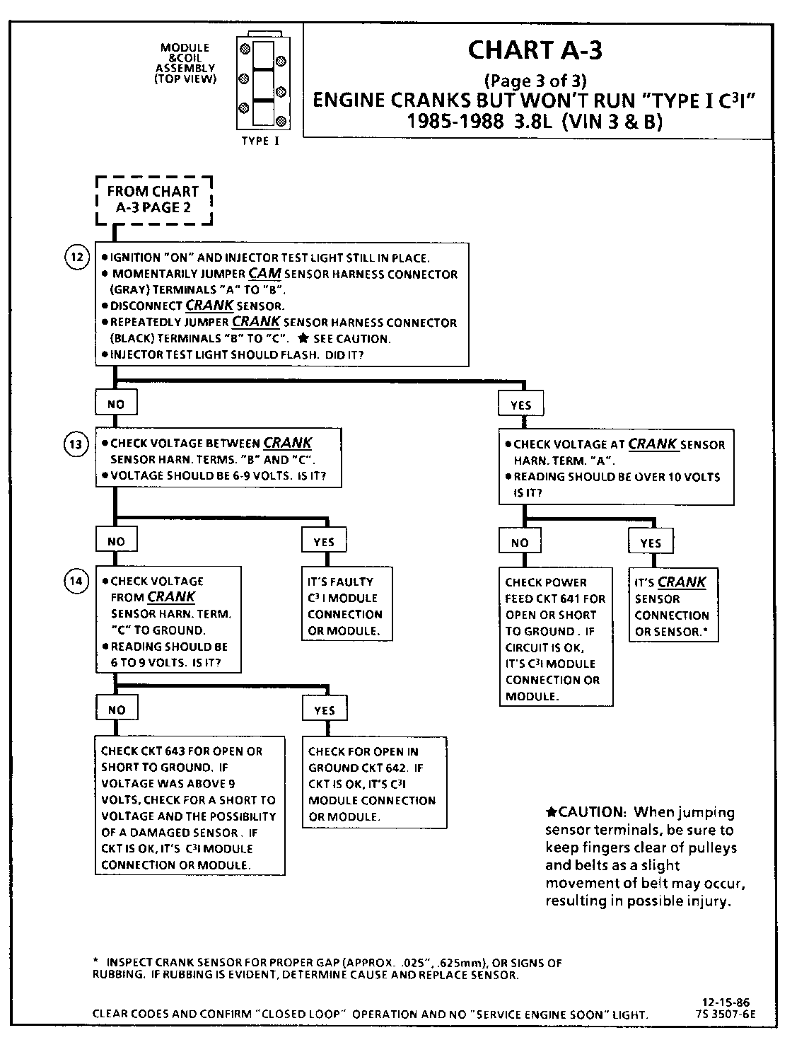
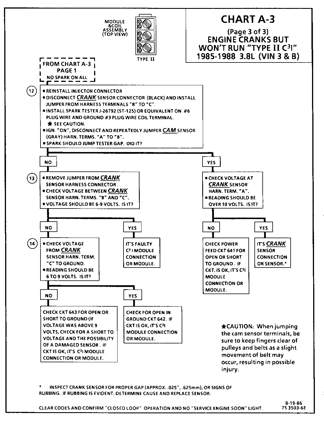
CHART A-3 (Page 3 of 3) ENGINE CRANKS BUT WON'T RUN "TYPE I C3I" 1986-1987 3.8L (VIN 3 & B)
Circuit Description:
For timing of spark plug firing, a cam sensor "hall effect" switch is used. The cam sensor sends a signal (Sync-Pulse) to the ignition module when cylinder #1 is 25 DEG after top dead center on the compression stroke. This signal is used to start the correct coil firing sequence and to enable sequential fuel injection. The engine will continue to run if the cam signal to the ignition module (CKT 633) is lost, however, will not restart after shut down and a Code 41 will be stored.
The crank sensor sends a signal to the ignition module and then to the ECM for reference rpm and crankshaft position. There are three windows in a disc (interruptor) which is mounted to the harmonic balancer. As these windows pass by the sensor, the next ignition coil is triggered.
Test Description: Numbers below refer to circled numbers on the diagnostic chart.
12. Jumping the cam sensor harness terminals "A" and "B" together simulates a cam signal to the C3I module. Then, by repeatedly jumping the crank sensor harness terminals "B" and "C" together a crank signal is simulated which should result in the injector test light blinking.
13. Verifies a proper crank signal circuit voltage of 6 to 9 voits and a good ground from the C3I module to te rminal "B" of the sensor connector.
14. Determines if incorrect voltage reading was due to a fault in CKT 643, an open in CKT 642 or a faulty C31 module.
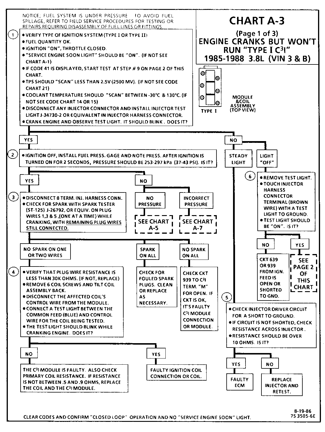
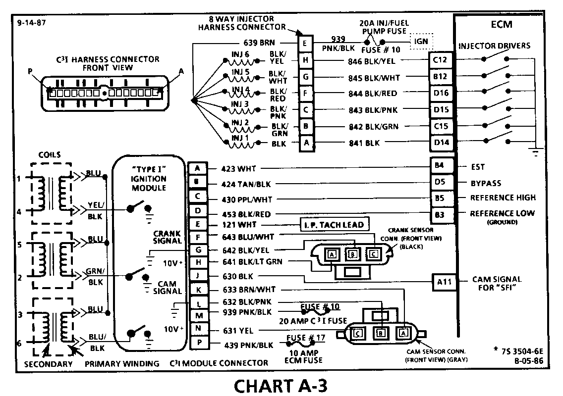
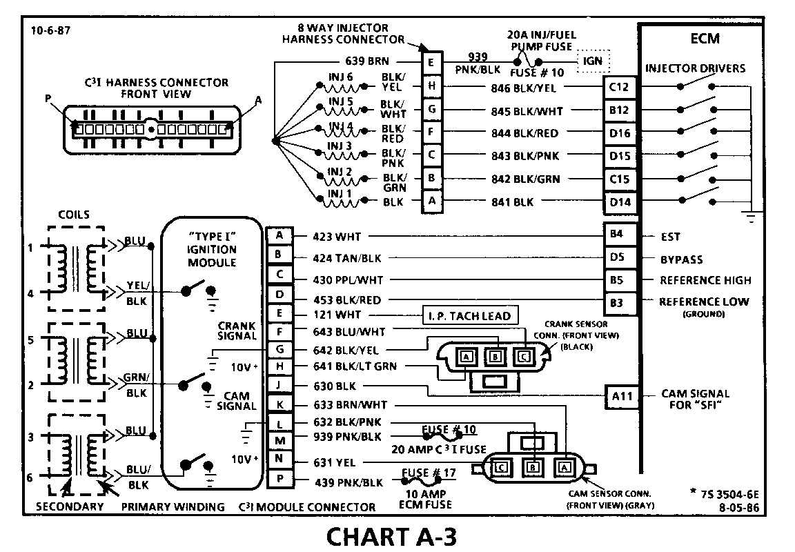
CHART A-3 (Page 1 of 3) ENGINE CRANKS BUT WON'T RUN "TYPE II C3I" 1986-1987 3.8L (VIN 3 & B)
Circuit Description:
The C31 uses a waste spark method of spark distribution. In this type of ignition system the ignition module triggers the # 1/4 coil pair resulting in both # 1 and #4 spark plugs firing at the same time. # 1 cylinder is on the compression stroke at the same time #4 is on the exhaust stroke, resulting in a lower energy requirement to fire #4 spark plug. This leaves the remaining high voltage to fire # 1 spark plug.
The Sequential Fuel Injection type of fuel delivery system utilizes 6 seperate injector driver circuits to activate the 6 fuel injectors. While cranking, the ECM activates all 6 injectors simultaneously (all at one time). After a calibrated engine rpm is reached, and a good Cam signal has been received by the ECM, the injection mode of operation is changed to Sequential (timed seperately).
Test Description: Numbers below refer to circled numbers on the diagnostic chart.
1. Identification of "TYPE I" or "TYPE II" ignition system is very important, because t he "TYPE II" diagnostics will not work on "TYPE I" systems. Identification can be made by comparing the position of the coil towers with the drawing at the top of the chart. This step verifies "SES" light operation, TPS, and Coolant Sensor signals are normal. A blinking injector test light verifies that the ECM is monitoring the C3I reference signal and attempting to activate the injectors.
2. The blinking injector test light verifies a working Cam Sensor. A fuel pressure test, at this point, will seperate the diagnostic path into either a fuel related fault or ignition system malfunction.
3. The 8 terminal injector harness connector must be disconnected to avoid flooding of the engine and fouling of the spark plugs. By testing for spark on plug leads 1, 3 and 5, each ignition coil's ability to produce at least 25,000 volts is verified. An erratic spark may be an indication of an open secondary winding in one of the ignition coils. This can result in internal arcing which may seek ground through the C3I module resulting in a stall or "Cranks But Won't Run" condition.
4. By switching the problem coil with a working one, a determination can be made as to the problem coil being faulty or the module's internal driver for that coil being the source of the complaint.
5. An injector with a resistance value of less than 10 ohms (shorted) must be replaced.
6. Tests for batterv voltage on CKT 639 and/or 939. If voltage was present, the light "OFF" resulted from the injector not receiving an pulse from the ECM.
CHART A-3 (Page 2 of 3) ENGINE CRANKS BUT WON'T RUN "TYPE II C3I" 1986-1987 3.8L (VIN 3 & B)
Circuit Description:
For timing of spark plug firing, a cam sensor "hall effect" switch is used. The cam sensor sends a signal (Sync-Pulse) to the ignition module when cylinder #1 is 25 DEG after top dead center on the compression stroke. This signal is used to start the correct sequence of coil firing and to enable sequential fuel injection. The engine will continue to run if the cam signal to the ignition module (CKT 633) is lost, however, will not restart after shut down and a Code 41 will be stored.
The crank sensor sends a signal to the ignition module and then to the ECM for reference rpm and crankshaft position. There are three windows in a disc (interruptor) which is mounted to the harmonic balancer. As these windows pass by the sensor, the next ignition coil is triggered.
Test Description: Numbers below refer to circled numbers on the diagnostic chart.
7. Verifies ignition feed voltage at terminal "M" of the C3I module. Less than battery voltage would be an indication of a CKT 939 fault.
8. The test light to 12 volts simulates a reference signal to the ECM which will result in an injector test light blink. This validates CKT 430, the ECM and the injector driver circuit.
9. If the Cam Sensor signal circuit terminal "A" is jumped to the ground circuit terminal "B", the response should be an injector test light blink.
This is a result of this artificial "Cam Signal" being transmitted through the C3I module to ECM terminal "All" and the ECM activating the injector driver circuit.
10. Verifies a proper Cam signal circuit voltage of 6 to 9 volts and a good ground from the C3I module to terminal "B" of the sensor connector.
11. Determines if incorrect voltage reading was due to a fault in CKT 633, an open in CKT 632 or a faulty C3I module.
CHART A-3 (Page 3 of 3) ENGINE CRANKS BUT WON'T RUN "TYPE II C3I" 1986-1987 3.8L (VIN 3 & B)
Circuit Description:
For timing of spark plug firing, a cam sensor "hall effect" switch is used. The cam sensor sends a signal (Sync-Pulse) to the ignition module when cylinder #1 is 25 DEG after top dead center on the compression stroke. This signal is used to start the correct sequence of coil firing and to enable sequential fuel injection. The engine will continue to run if the cam signal to the ignition module (CKT 633) is lost, however, will not restart after shut down and a Code 41 will be stored.
The crank sensor sends a signal to the ignition module and then to the ECM for reference rpm and crankshaft position. There are three windows in a disc (interruptor) which is mounted to the harmonic balancer. As these windows pass by the sensor, the next ignition coil is triggered.
Test Description: Numbers below refer to circled numbers on the diagnostic chart.
12. Jumping the Crank Sensor harness terminals "B" and "C" together simulates a Crank signal to the C3I module. Then, by repeatedly jumping the Cam sensor harness terminals "A" and "B" together a Cam signal is simulated which should result in a spark.
13. Verifies a proper Crank signal circuit voltage of 6 - to 9 volts and a good ground from the C3I module to terminal "B" of the sensor connector.
14. Determines if incorrect voltage reading was due to a fault in CKT 643, an open in CKT 642 or a faulty C3I module.
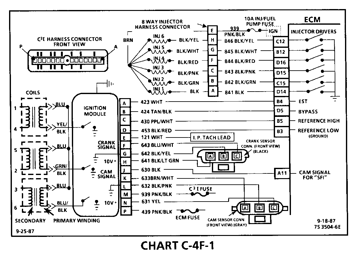
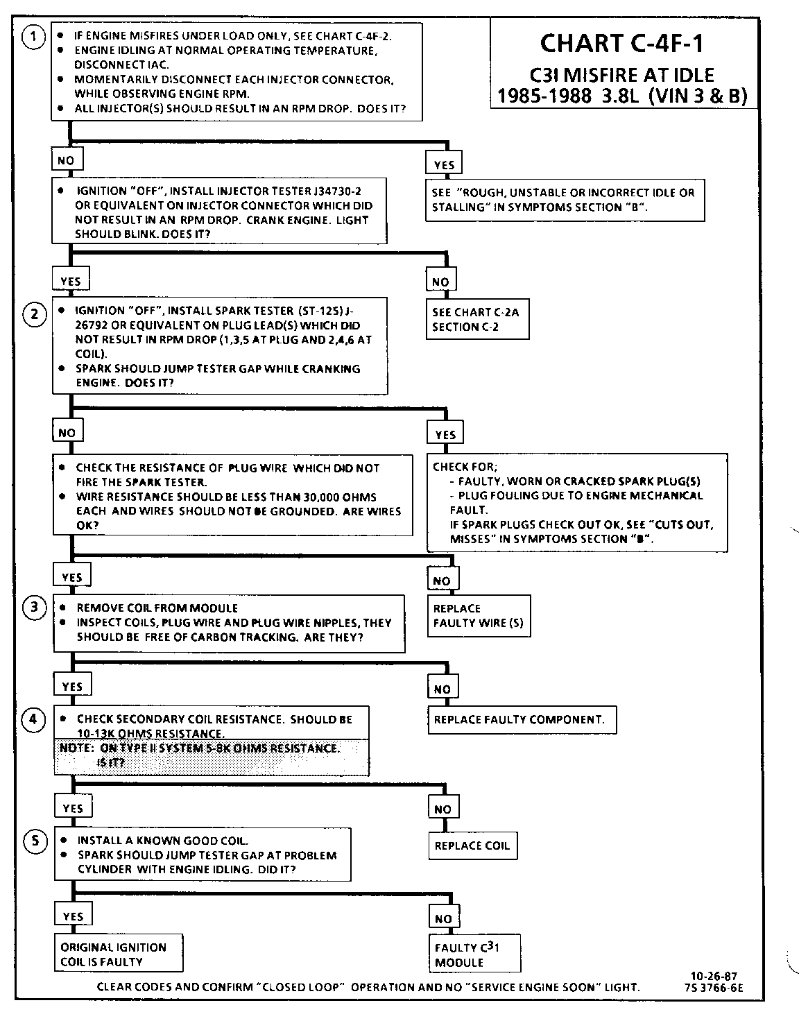
CHART C-4F-1 C3I MISFIRE AT IDLE 1986-1987 3.8L (VIN 3 & B)
Circuit Description:
The C3I uses a waste spark method of spark distribution. In this type of ignition system the ignition module triggers the #1/4 coil pair resulting in both #1 and #4 spark plugs firing at the same time. #1 cylinder is on the compression stroke at the same time #4 is on the exhaust stroke, resulting in a lower energy requirement to fire #4spark plug. This leaves the remaining high voltage to fire #1 spark plug.
Test Description: Numbers below refer to circled numbers on the diagnostic chart.
1. If the "misfire" complaint exists under load only, diagnostic CHART C-4F-2 must be used. Engine rpm should drop approximately equally on all plug leads.
2. A spark tester such as a ST-125 must be used because it is essential to verify adequate available secondary voltage at the spark plug. (25,000 volts.). Secondary voltage of at least (25,000 voits) must be present to jump the gap of a ST-125.
3. If ignition coils are carbon tracked, the coil tower spark plug wire nipples may be damaged.
4. By checking the secondary resistance, a coil with an open secondary may be located.
5. By switching a normally operating coil into the position of the malfunctioning one, a determination can be made as to fault being the coil or C3I module.
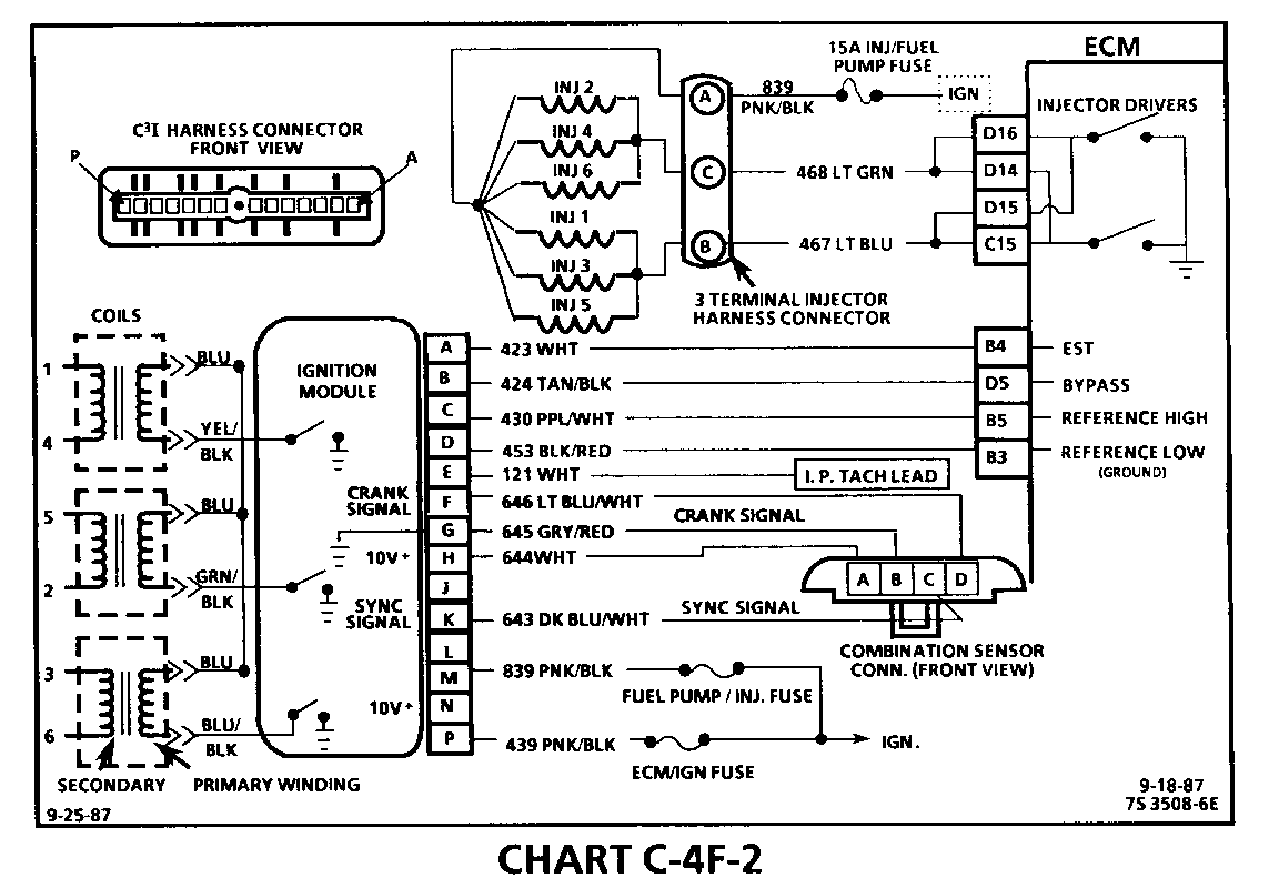
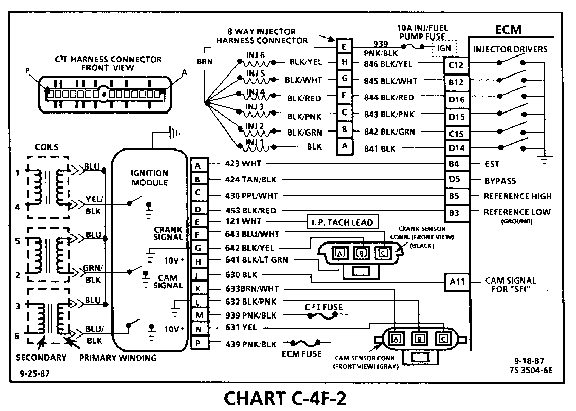
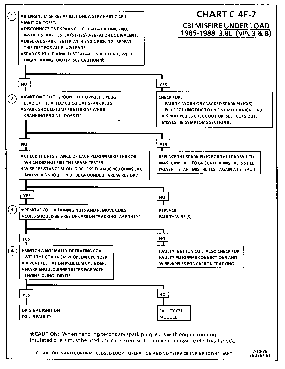
CHART C-4F-2 C31 MISFIRE UNDER LOAD 1986-1987 3.8L (VIN 3 & B)
Circuit Description:
The C3I uses a waste spark method of spark distribution. In this type of ignition system the ignition module triggers the #1/4 coil pair resulting in both #1 and #4 spark plugs firing at the same time. #1 cylinder is on the compression stroke at the same time #4 is on the exhaust stroke, resulting in a lower energy requirement to fire #4 spark plug. This leaves the remaining high voltage to fire # 1 spark plug.
Test Description: Numbers below refer to circled numbers on the diagnostic chart.
1. If the "misfire" complaint exists at idle only, diagnostic CHART C-4F-I must be used.
2. A spark tester such as a ST-125 must be used because it is essential to verify adequate available secondary voltage at the spark plug. (25,000 volts). Spark should jump the tester gap on all 6 leads. This simulates a "load" condition.
3. If ignition coils are carbon tracked, the coil tower spark plug wire nipples may be damaged.
4. By switching a normally operating coil into the position of the malfunctioning one, a determination can be made as to fault being the coil or C3I module.
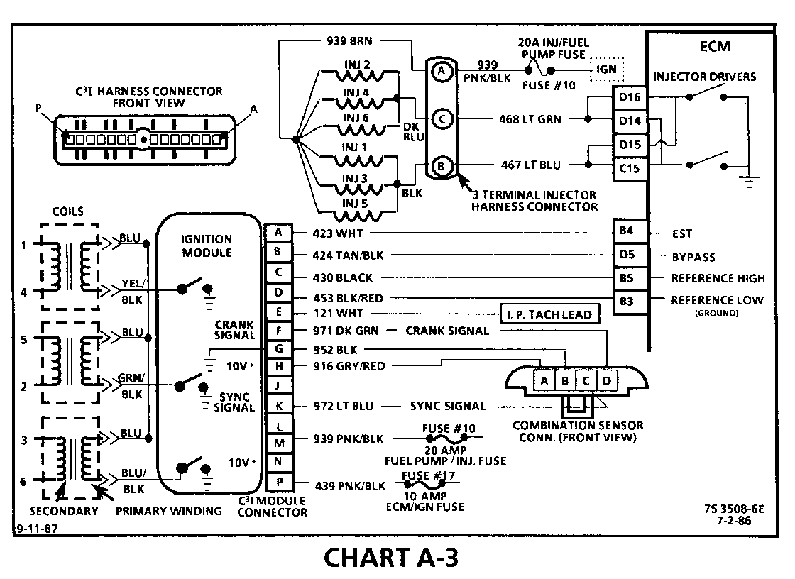
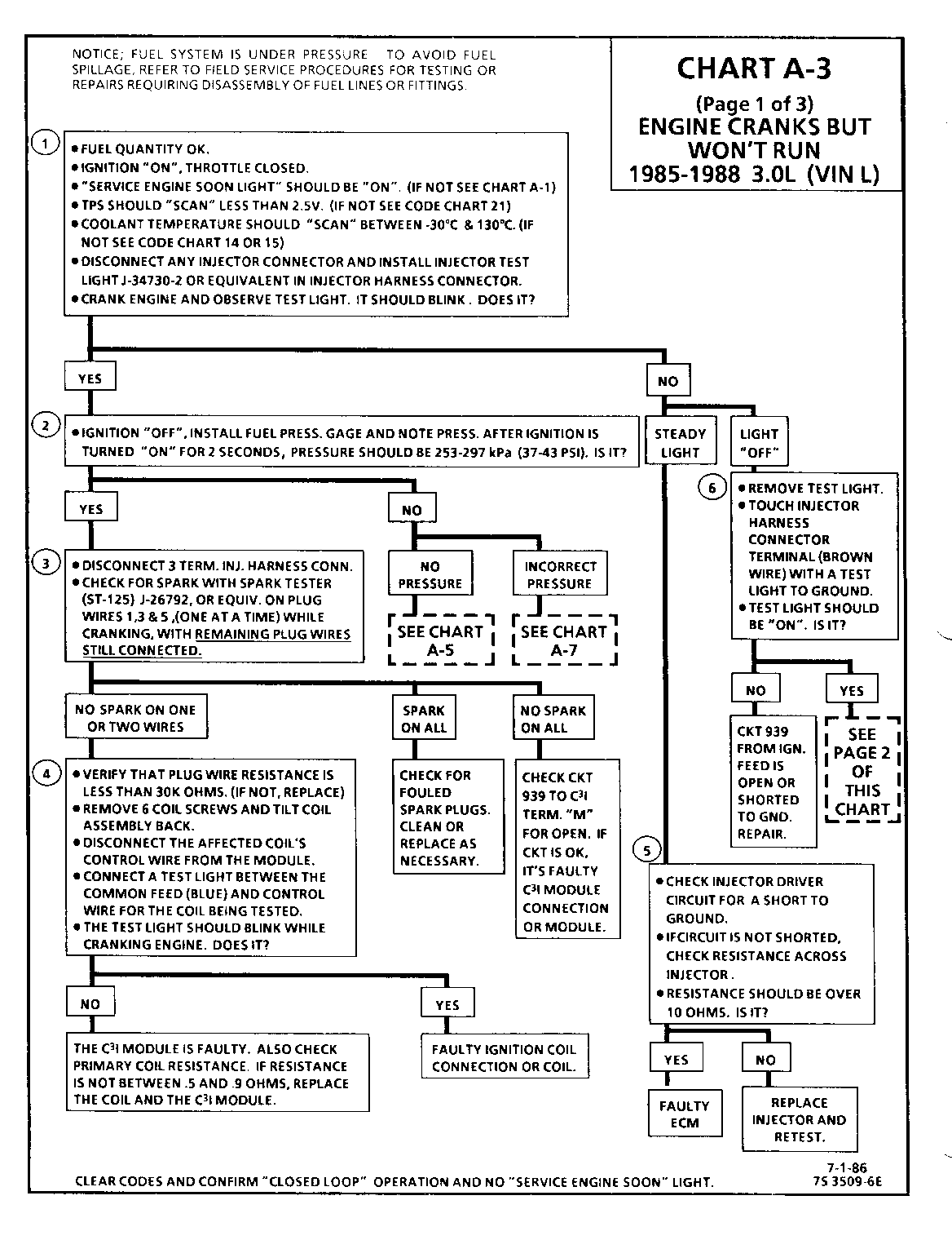
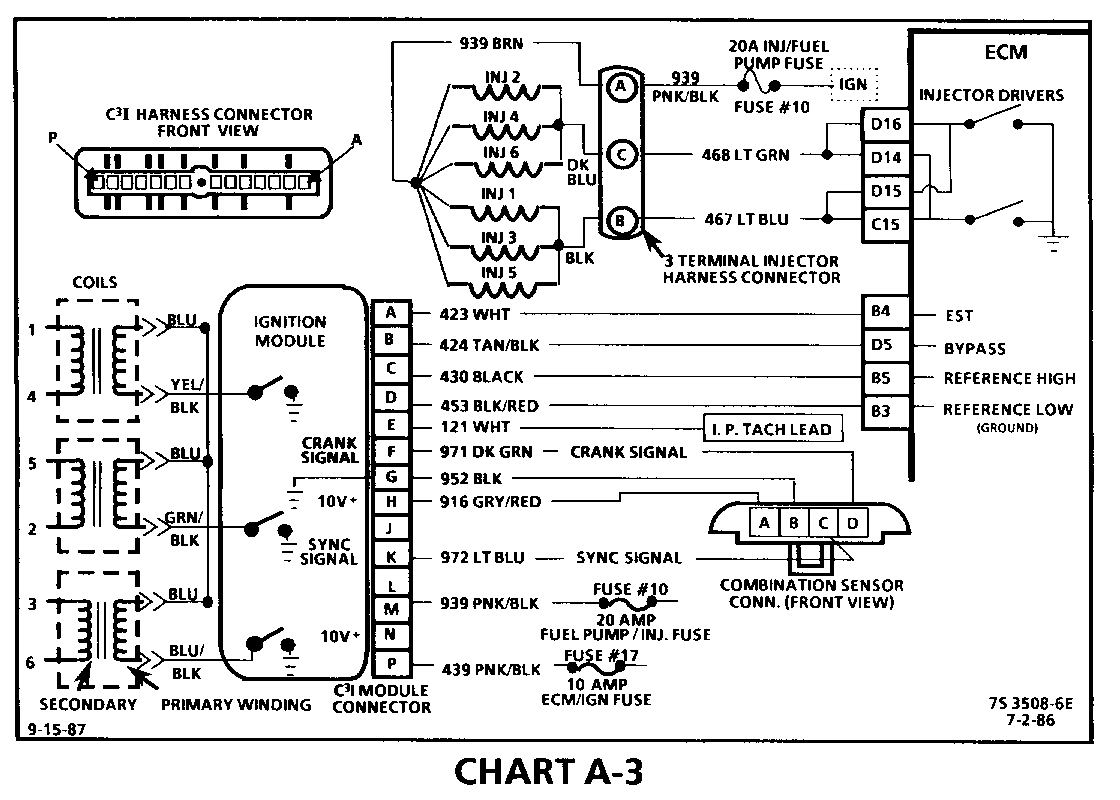
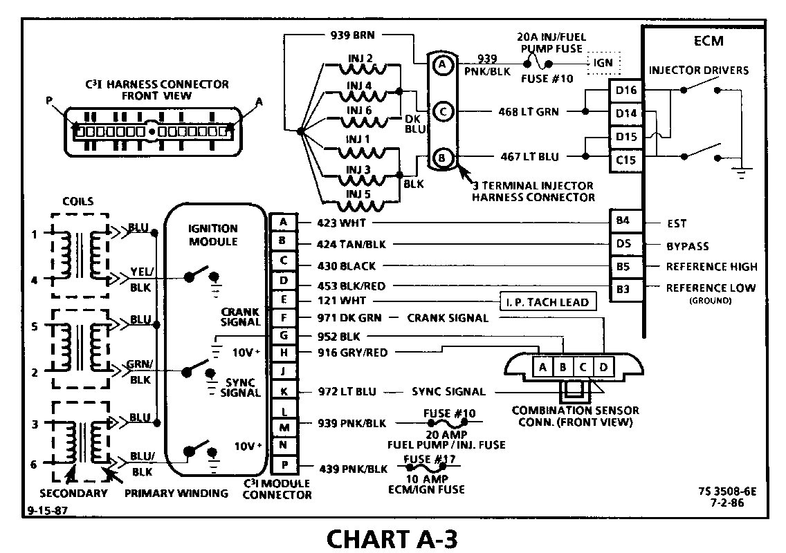
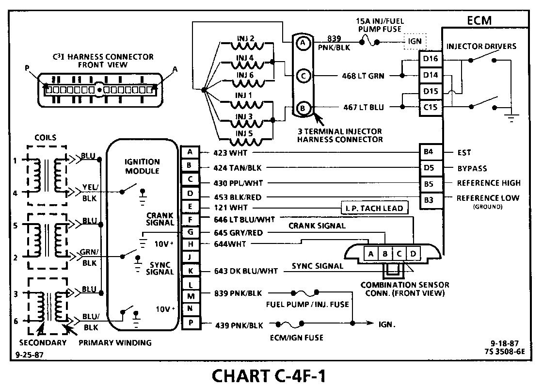
CHART A-3 (Page 1 of 3) ENGINE CRANKS BUT WON'T RUN 1986-1987 3.0L (VIN L)
Circuit Description:
The C3I uses a waste spark method of spark distribution. In this type of ignition system the ignition module triggers the #1/4 coil pair resulting in both #1 and #4 spark plugs firing at the same time. #1 cylinder is on the compression stroke at the same time #4 is on the exhaust stroke, resulting in a lower energy requirement to fire #4 spark plug. This leaves the remaining high voltage to fire # 1 spark plug.
This Simultaneous Fuellnjection type of fuel delivery system utilizes 2 injector driver circuits in parallel, to activate the 6 individual fuel injectors. The ECM activates all 6 injectors simultaneously (all at one time).
Test Description: Numbers below refer to circled numbers on the diagnostic chart.
1. This step verifies that "SES" light operation, TPS and coolant sensor signals are normal. A blinking injector test light verifies that the ECM is monitoring the C3I reference signal and attempting to activate the injectors.
2. Both the "Sync-Pulse" and crank signals have been verified, as is evidenced by the blinking injector test light. A fuel pressure test at this point will seperate the diagnostic path into either a fuel related fault or ignition system malfunction.
3. The 3 terminal injector harness connector must be disconnected to avoid flooding of the engine and fouling of the spark plugs.
By testing for spark on plug leads 1, 3 and 5, each ignition coil's ability to produce at least 25,000 volts is verified.
4. By testing the problem coil's control circuit with a test light, a determination can be made as to the problem coil being faulty or the module's internal driver for that coil being the source of the complaint.
5. An injector with a resistance value of less than 10 ohms (shorted) must be replaced.
6. Tests for battery voltage on CKT 939. If voltage was present, the "light off" test result was caused by no activation pulse reaching the injector connector from the ECM.
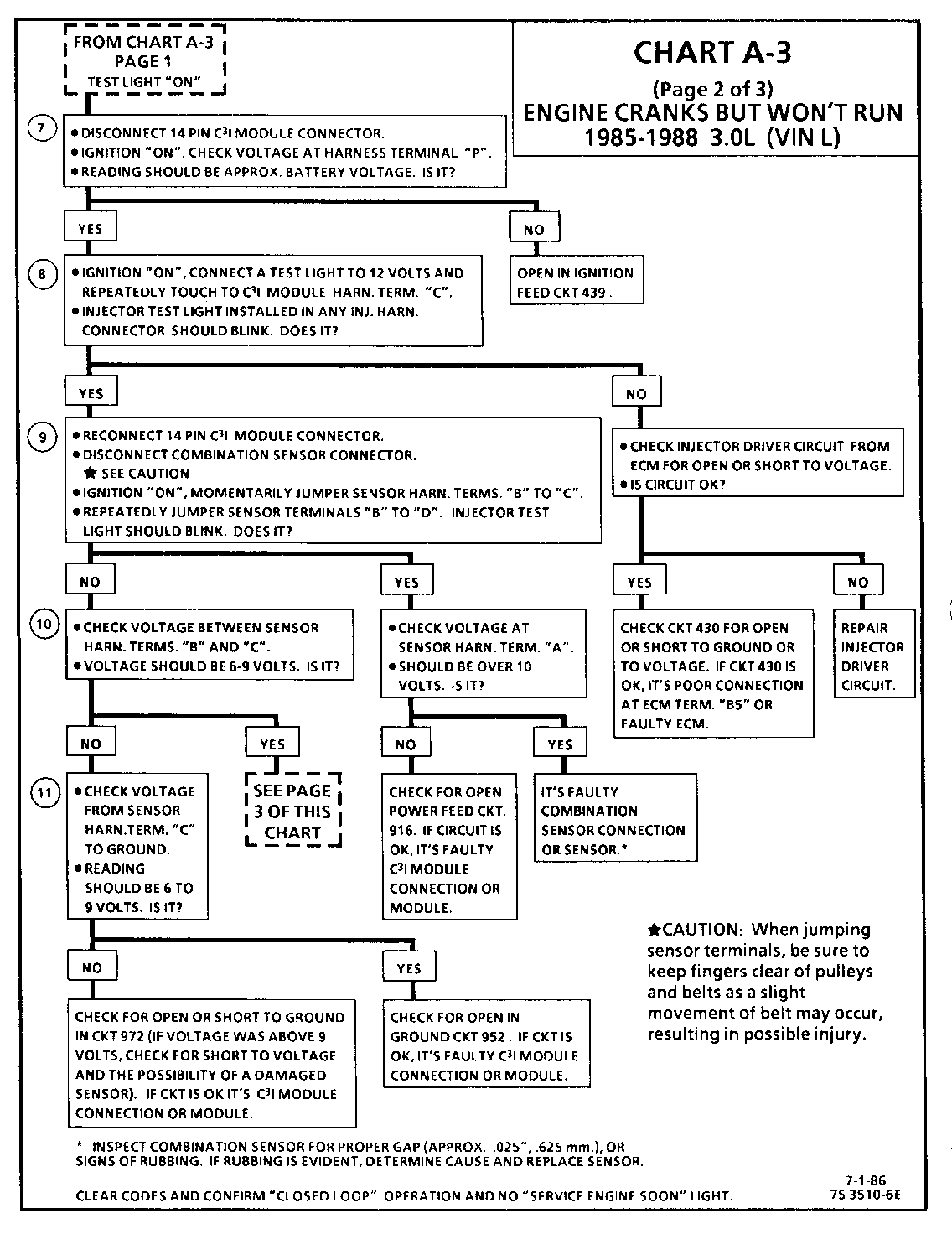
CHART A-3 (Page 2 of 3) ENGINE CRANKS BUT WON'T RUN 1986-1987 3.0L (VIN L)
Circuit Description:
For synchronization of spark plug firing, a "Sync-Pulse" is created by the combination sensor "hall effect" switch. The sensor sends the "Sync-Pulse" to the ignition module, when cylinders #1 and #4 are 25 DEG after top dead center. This signal is used to start the correct sequence of coil firing with the # 3/6 ignition coil.
The crank signal portion of the combination sensor sends a signal to the ignition module for coil activation and then to the ECM for reference rpm and crankshaft position. There are three windows in a disc (interruptor) which is mounted to the harmonic balancer. As these windows pass through the slot in the sensor, the next coil is triggered.
Test Description: Numbers below refer to circled numbers on the diagnostic chart.
7. Verifies ignition feed voltage at terminal "P" of the C3I module. Less than battery voltage would be an indication of a CKT 439 fault.
8. The test light to 12 volts simulates a reference signal to the ECM which will result in an injector test light blink. This will validate CKT 430, the ECM and the injector driver circuit are all OK.
9. Jumping the combination sensor harness terminals "B" and "C" together simulates a "Sync-Pulse" signal to the C3I module.
Then, by repeatedly jumping the combination sensor harness terminals "B" and "D" together, a crank signal is simulated, which should result in the injector test light blinking.
10. Verifies a proper "Sync-Pulse" signal circuit voltage of 6 to 9 volts and a good ground from the C3I module to terminal "B" of the sensor connector.
11. Determines if reason for incorrect voltage reading was due to a fault in CKT 972, an open in CKT 952, or a faulty C3I module. If the C3 module was faulty, also verify that CKT 453 to ECM terminal "B3" is not open.
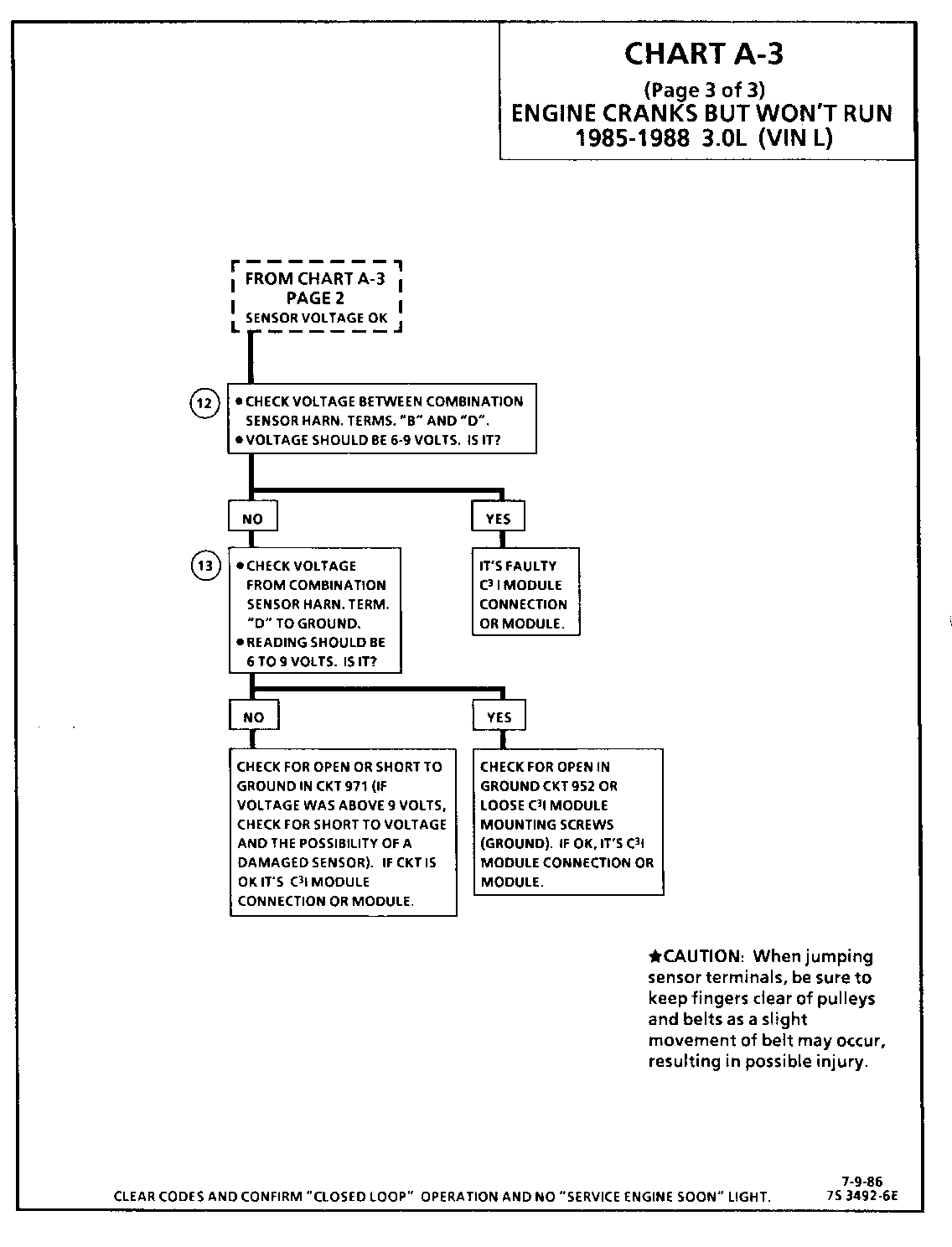
CHART A-3 (Page 3 of 3) ENGINE CRANKS BUT WON'T RUN 1986-1987 3.0L (VIN L)
Circuit Description:
For synchronization of spark plug firing, a "Sync-Pulse" is created by the combination sensor "hall effect" switch. The sensor sends the "Sync-Pulse" to the ignition module when cylinders # 1 and #4 are 25 DEG after top dead center. This signal is used to start the correct sequence of coil firing with the # 3/6 ignition coil.
The crank signal portion of the combination sensor sends a signal to the ignition module for coil activation and then to the ECM for reference rpm and crankshaft position. There are three windows in a disc (interruptor) which is mounted to the harmonic balancer. As these windows pass through the slot in the sensor, the next coil is triggered.
Test Description: Numbers below refer to circled numbers on the diagnostic chart.
12. Verifies a proper Crank signal circuit voltage of 7 to 9 volts and a good ground from the C31 module to terminal "B" of the sensor con nector.
13. Determines if reason for incorrect voltage reading was due to a fault in CKT 971, an open in CKT 952 or a faulty C3I module.
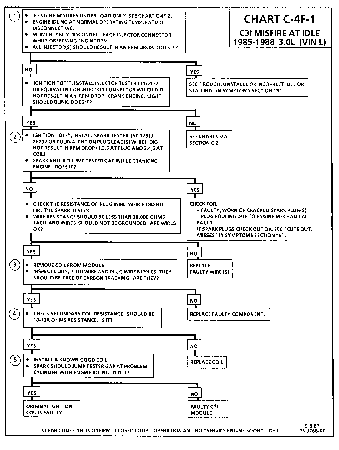
CHART C-4F-1 C3I MISFIRE AT IDLE 1986-1987 3.0L (VIN L)
Circuit Description:
The C3I uses a waste spark method of spark distribution. In this type of ignition system the ignition module triggers the #1/4 coil pair resulting in both #l and #4 spark plugs firing at the same time. #l cylinder is on the compression stroke at the same time #4 is on the exhaust stroke, resulting in a lower energy requirement to fire #4 spark plug. This leaves the remaining high voltage to fire # 1 spark plug.
Test Description: Numbers below refer to circled numbers on the diagnostic chart.
1. If the "misfire" complaint exists under load only, diagnostic CHART C-4F-2 must be used. Engine rpm should drop approximately equally on all plug leads.
2. A spark tester such as a ST-125 must be used because it is essential to verify adequate available secondary voltage at the spark plug. (25,000 volts.). Secondary voltage of at least (25,000 volts) must be present to jump the gap of a ST--125.
3. If ignition coils are carbon tracked, the coil tower spark plug wire nipples may be damaged.
4. By checking the secondary resistance, a coil with an open secondary may be located.
5. By switching a normally operating coil into the position of the malfunctioning one, a determination can be made as to fault being the coil or C31 module.
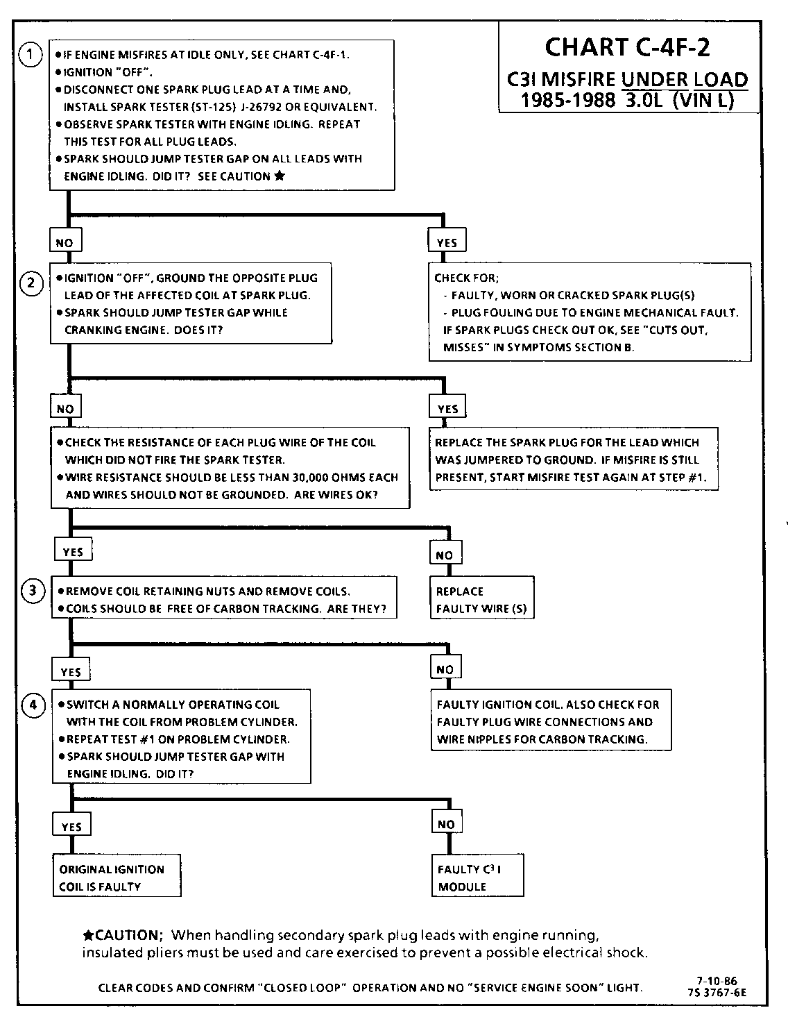
CHART C-4F-2 C3I MISFIRE UNDER LOAD 1986-1987 3.0L (VIN L)
Circuit Description:
The C3I uses a waste spark method of spark distribution. In this type of ignition system the ignition module triggers the # 1/4 coil pair resulting in both # 1 and #4 spark plugs firing at the same time. # 1 cylinder is on the compression stroke at the same time #4 is on the exhaust stroke, resulting in a lower energy requirement to fire #4 spark plug. This leaves the remaining high voltage to fire #1 spark plug.
Test Description: Numbers below refer to circled numbers on the diagnostic chart.
1. If the "misfire" complaint exists at idle only, diagnostic CHART C-4F-1 must be used.
2. A spark tester such as a ST-125 must be used because it is essential to verify adequate available secondary voltage at the spark plug, (25,000 volts). Spark should jump the tester gap on all 6 leads. This simulates a "load" condition.
3. If ignition coils are carbon tracked, the coil tower spark plug wire nipples may be damaged.
4. By switching a normally operating coil into the position of the malfunctioning one, a determination can be made as to fault being the coil or C31 module.
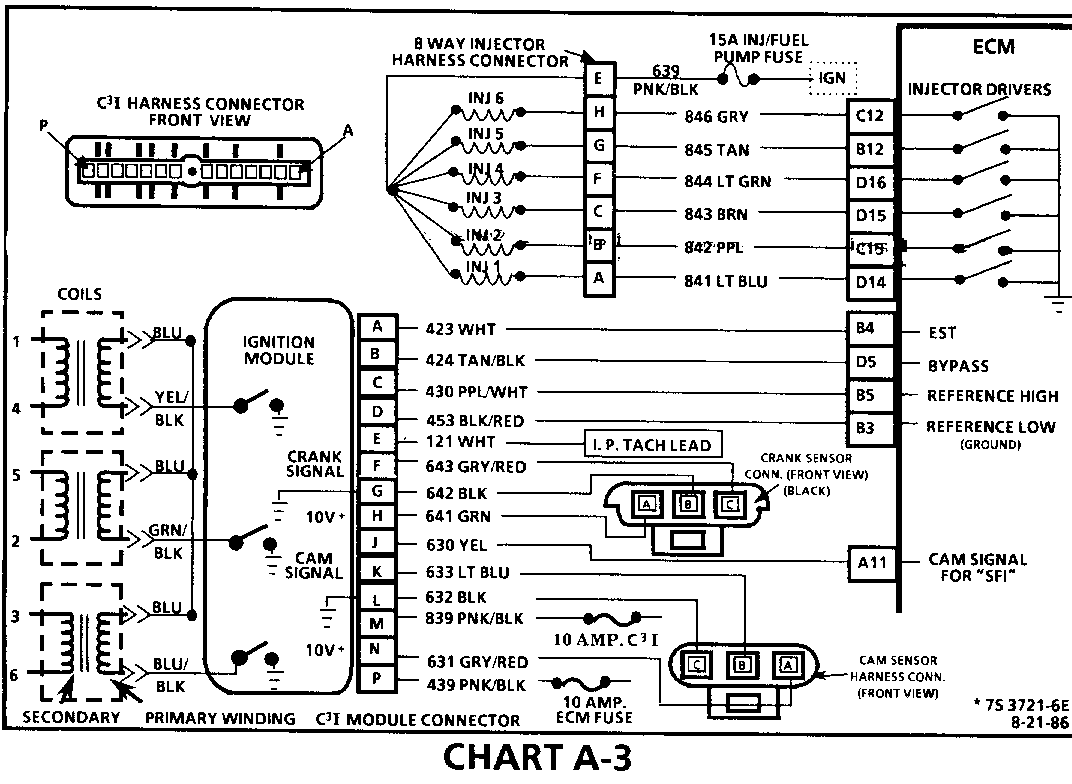
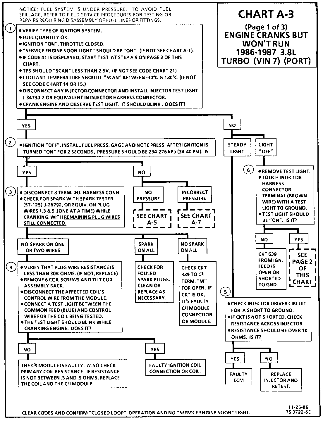
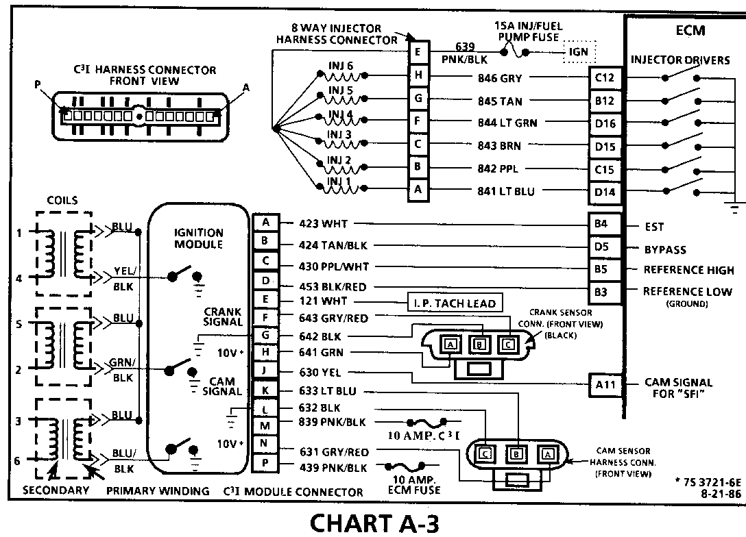
CHART A-3 (Page 1 of 3) ENGINE CRANKS BUT WON'T RUN 1986-1987 3.8L TURBO (VIN 7) (PORT) Circuit Description:
The C3I uses a waste spark method of spark distribution. In this type of ignition system the ignition module triggers the #1/4 coil pair resulting in both #1 and #4 spark plugs firing at the same time. #1 cylinder is on the compression stroke at the same time #4 is on the exhaust stroke, resulting in a lower energy requirement to fire #4 spark plug. This leaves the remaining high voltage to fire #1 spark plug.
The Sequential Fuel Injection type of fuel delivery system utilizes 6 separate injector driver circuits to activate the 6 fuel injectors. While cranking, the ECM activates all 6 injectors simultaneously (all at one time). After a calibrated engine rpm is reached and a good Cam signal has been received by the ECM, the injection mode of operation is changed to Sequential (timed seperately).
Test Description: Step numbers refer to step numbers on diagnostic chart.
1. This step verifies "SES" light operation, TPS and Coolant Sensor signals are normal. A blinking injector test light verifies that the ECM is monitoring the C3I reference signal and attempting to activate the injectors.
2. Both the Cam and Crank Sensors have been verified as functioning properly as is evidenced by the blinking injector test light. A fuel pressure test, at this point, will separate the diagnostic path into either a fuel related fault, or ignition system malfunction.
3. The 8 terminal injector harness connector must be disconnected to avoid flooding of the engine and fouling of the spark plugs. By testing for spark on plug leads 1, 3, and 5, each ignition coil's ability to produce at least 25,000 volts is verified.
4. By testing the problem coil's control circuit with a test light, a determination can be made as to the problem coil being faulty or the module's internal driver for that coil being the source of the complaint.
5. An injector with a resistance value of less than 10 ohms (shorted) must be replaced.
6. Tests for battery voltage on CKT 639. If voltage was present, the "light off" test result was caused by no activation pulse reaching the injector connector from the ECM.
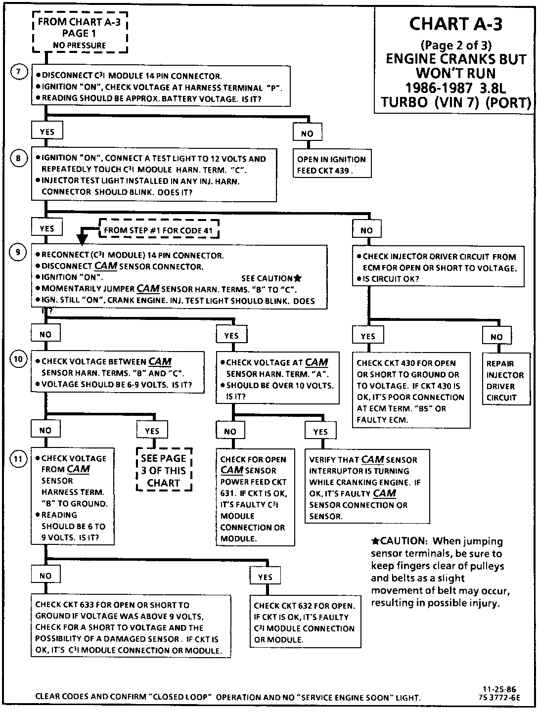
CHART A-3 (Page 2 of 3) ENGINE CRANKS BUT WON'T RUN 1986-1987 3.8L TURBO (VIN 7) (PORT)
Circuit Description:
For timing of spark plug firing, a cam sensor "hall effect" switch is used. The cam sensor sends a signal (Sync-Pulse) to the ignition module when cylinder #1 is 25 DEG after top dead center on the compression stroke. This signal is used to start the correct coil firing sequence and to enable sequential fuel injection. The engine will continue to run if the cam signal to the ignition module (CKT 633) is lost, however, will not restart after shut down and a Code 41 will be stored.
The crank sensor sends a signal to the ignition module and then to the ECM, for reference rpm and crankshaft position. There are three windows in a disc (interruptor) which is mounted to the harmonic balancer. As these windows pass by the sensor, the next coil is triggered.
Test Description: Step numbers refer to step numbers on diagnostic chart.
7. Verifies ignition feed voltage at terminal "P" of the C3I module. Less than battery voltage would be an indication of a CKT 439 fault.
8. The test light to 12 volts simulates a reference signal to the ECM which will result in a injector test light blink. This test validates CKT 430, the ECM and the injector driver circuits.
9. If the Cam sensor signal circuit, terminal "B", is momentarily jumpered to the ground circuit, terminal "C", and the engine is cranked without turning the ignition switch "OFF", the response should be an injector test light blink. This is a result of the artificial "Cam Signal" being transmitted through the C3I module to ECM terminal "All" and the ECM activating the injector driver circuit.
10. Verifies a proper Cam signal circuit voltage of 6 to 9 volts and a good ground from the C3I module terminal "C" of the sensor connector.
11. Determines if the incorrect voltage reading was due to a fault in CKT 633, an open in CKT 632 on a faulty C3I module.
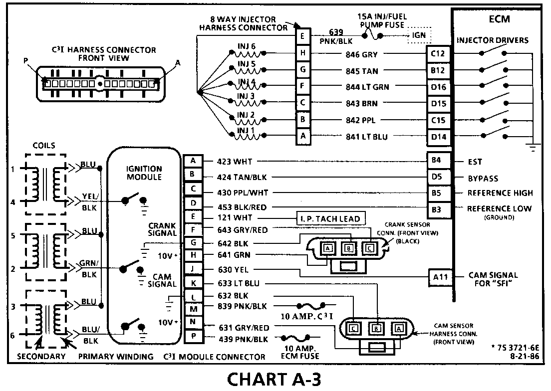
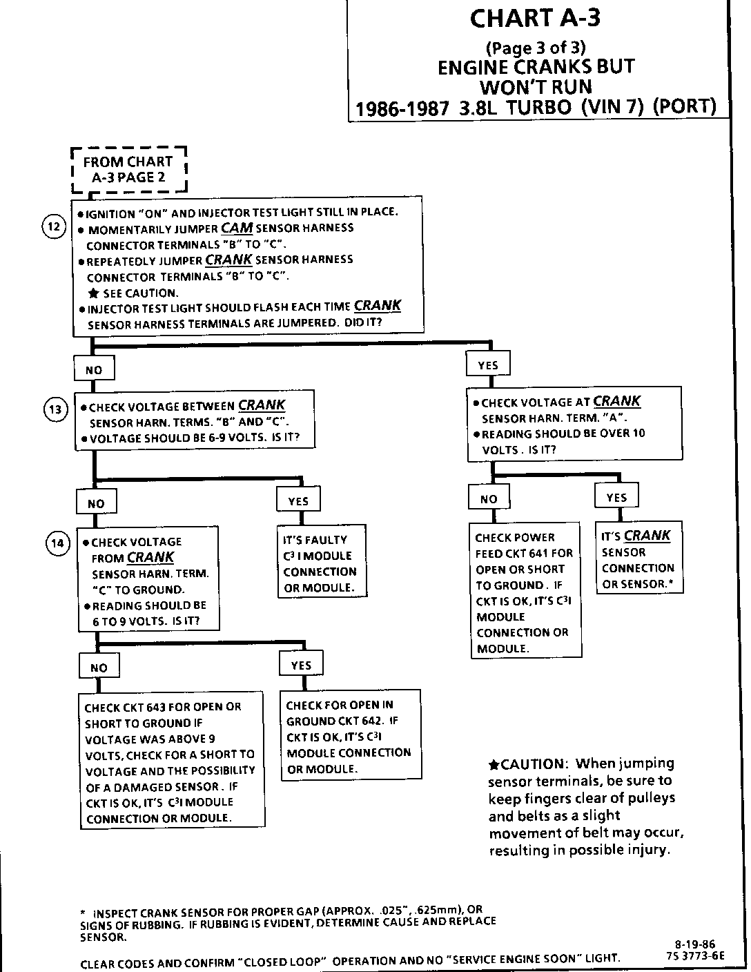
CHART A-3 (Page3 of 3) ENGINE CRANKS BUT WON'T RUN 1986-1987 3.8L TURBO (VIN 7) (PORT)
Circuit Description:
For timing of spark plug firing, a cam sensor "hall effect" switch is used. The cam sensor sends a signal (Sync-Pulse) to the ignition module when cyiinder #1 is 25 DEG after top dead center on the compression stroke. This signal is used to start the correct coil firing sequence and to enable sequential fuel injection. The engine will continue to run if the cam signal to the ignition module (CKT 633) is lost, however, will not restart after shut down and a Code 41 will be stored.
The crank sensor sends a signal to the ignition module and then to the ECM for reference rpm and crankshaft position. There are three windows in a disc (interruptor) which is mounted to the harmonic balancer. As these windows pass by the sensor, the next coil is triggered.
Test Description: Step numbers refer to step numbers on diagnostic chart.
12. Jumpering the Crank Sensor harness terminals "B" and "C" together simulates a Cam signal to the C3I module. Then, by repeatedly jumping the Crank sensor harness terminals "B" and "C" together a Crank signal is simulated which should result in the injector,test light blinking.
13. Verifies a proper Crank signal circuit voltage of 6 to 9 volts and a good ground from the C3I module to terminal "B" of the sensor connector.
14. Determines if the incorrect voltage reading was due to a fault in C KT 643, an open in C KT 642 or a faulty C3I module.
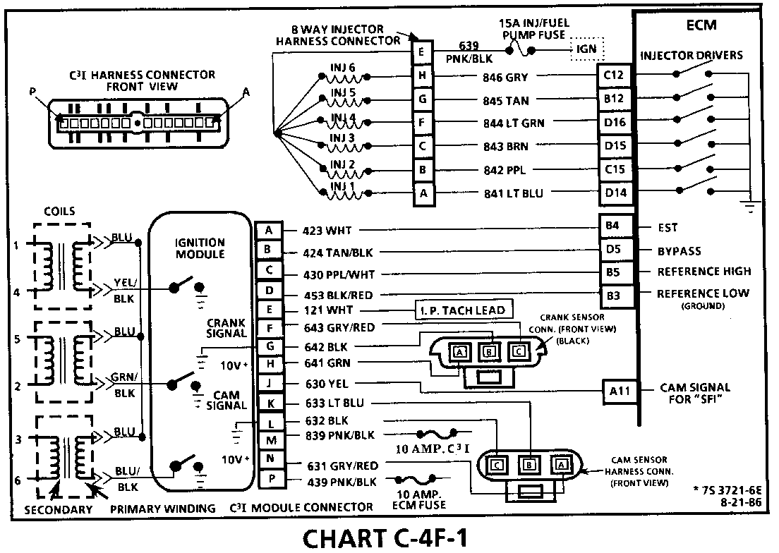
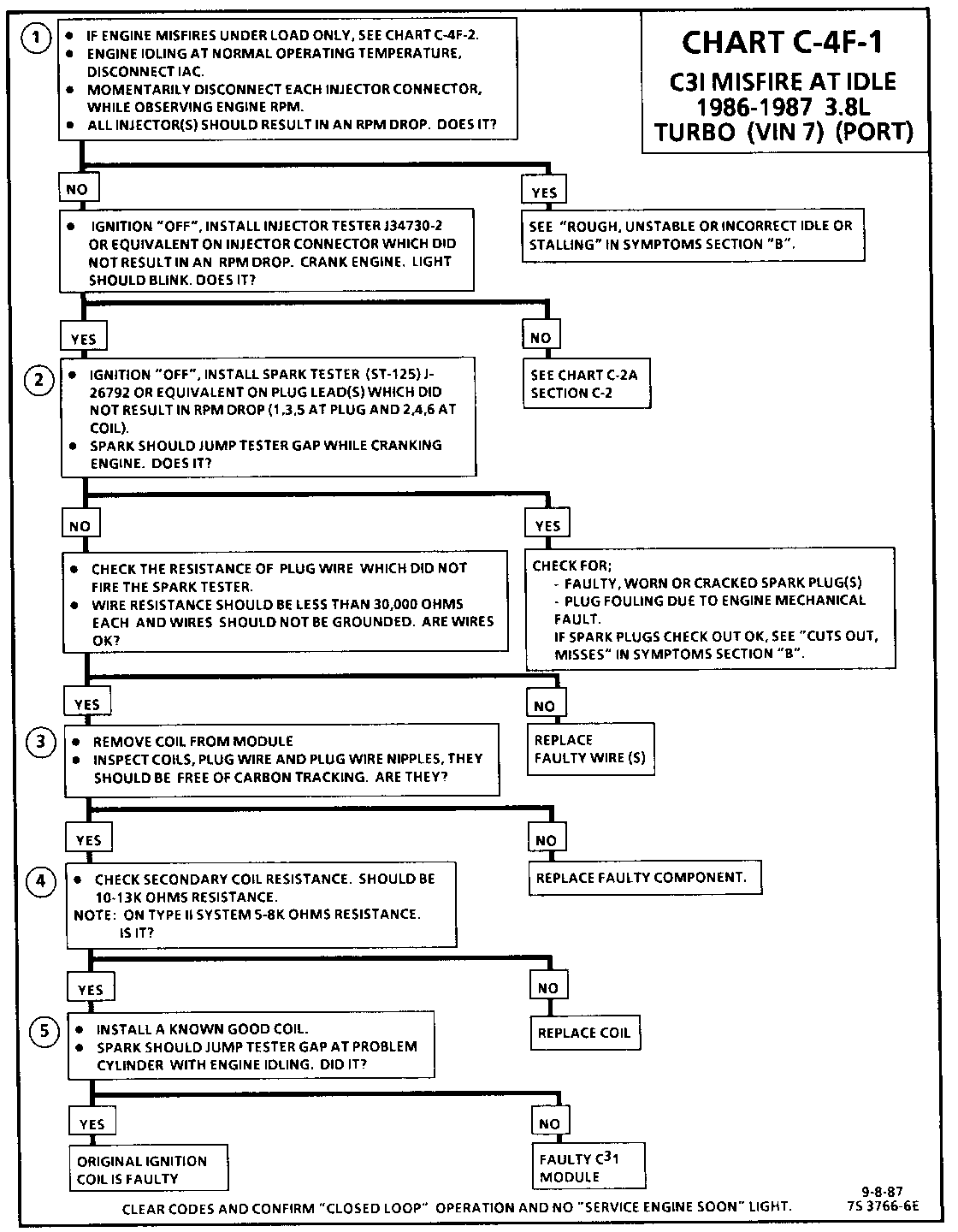
CHART C-4F-1 C3I MISFIRE AT IDLE 1986-1 87 3.8L TURBO VIN 7) (PORT)
Circuit Description:
The C3I uses a waste spark method of spark distribution. In this type of ignition system the ignition module triggers the # 1/4 coil pair resulting in both # 1 and #4 spark plugs firing at the same time. #1 cylinder is on the compression stroke at the same time #4 is on the exhaust stroke, resulting in a lower energy requirement to fire #4 spark plug. This leaves the remaining high voltage to fire #1 spark plug.
Test Description: Numbers below refer to circled numbers on the diagnostic chart.
1. If the "misfire" complaint exists under load only, diagnostic CHART C-4F-2 must be used. Engine rpm should drop approximately equally on all plug leads.
2. A spark tester such as a ST-125 must be used because it is essential to verify adequate available secondary voltage at the spark plug. (25,000 volts.). Secondary voltage of at least (25,000 volts) must be present to jump the gap of a ST-125.
3. If ignition coils are carbon tracked, the coil tower spark plug wire nipples may be damaged.
4. By checking the secondary resistance, a coil with an open secondary may be located.
5. By switching a normally operating coil into the position of the malfunctioning one, a determination can be made as to fault being the coil or C3I module.
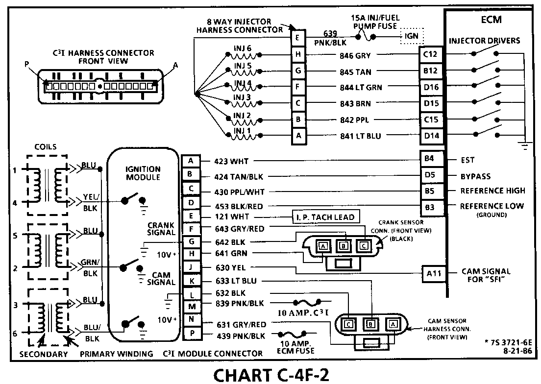
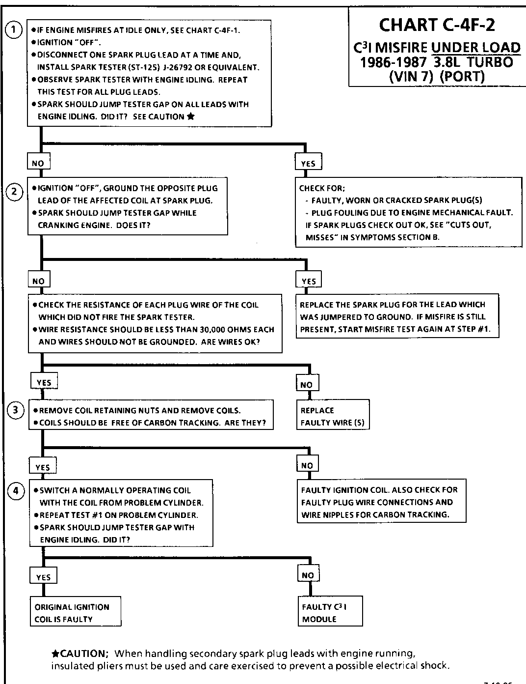
CHART C-4F-2 C3I MISFIRE UNDER LOAD 1986-1987 3.8L TURBO (VIN 7 (PORT)
Circuit Description:
The C3I uses a waste spark method of spark distribution. In this type of ignition system the ignition module triggers the # 1/4 coil pair resulting in both # 1 and #4 spark plugs firing at the same time. # 1 cylinder is on the compression stroke at the same time #4 is on the exhaust stroke, resulting in a lower energy requirement to fire #4 spark plug, This leaves the remaining high voltage to fire #1 spark plug.
Test Description: Numbers below refer to circled numbers on the diagnostic chart.
1. If the "misfiree" complaint exists at idle only, diagnostic CHART C-4F-I must be used.
2. A spark tester such as a ST-125 must be used because it is essential to verify adequate available secondary voltage at the spark plug. (25,000 volts). Spark should jump the tester gap on all 6 leads. This simulates a "load" condition.
3. If ignition coils are carbon tracked, the coil tower spark plug wire nipples may be damaged.
4. By switching a normally operating coil into the position of the malfunctioning one, a determination can be made as to fault being the coil or C3I module.
General Motors bulletins are intended for use by professional technicians, not a "do-it-yourselfer". They are written to inform those technicians of conditions that may occur on some vehicles, or to provide information that could assist in the proper service of a vehicle. Properly trained technicians have the equipment, tools, safety instructions and know-how to do a job properly and safely. If a condition is described, do not assume that the bulletin applies to your vehicle, or that your vehicle will have that condition. See a General Motors dealer servicing your brand of General Motors vehicle for information on whether your vehicle may benefit from the information.
