For 1990-2009 cars only
Removal Procedure
- Disconnect the negative battery cable. Refer to Battery Negative Cable Disconnection and Connection .
- Remove the drive belt. Refer to Drive Belt Replacement .
- Remove the fuel injector sight shield. Refer to Fuel Injector Sight Shield Replacement .
- Remove the engine mount strut bracket. Refer to Engine Mount Strut Bracket Replacement - Right Side .
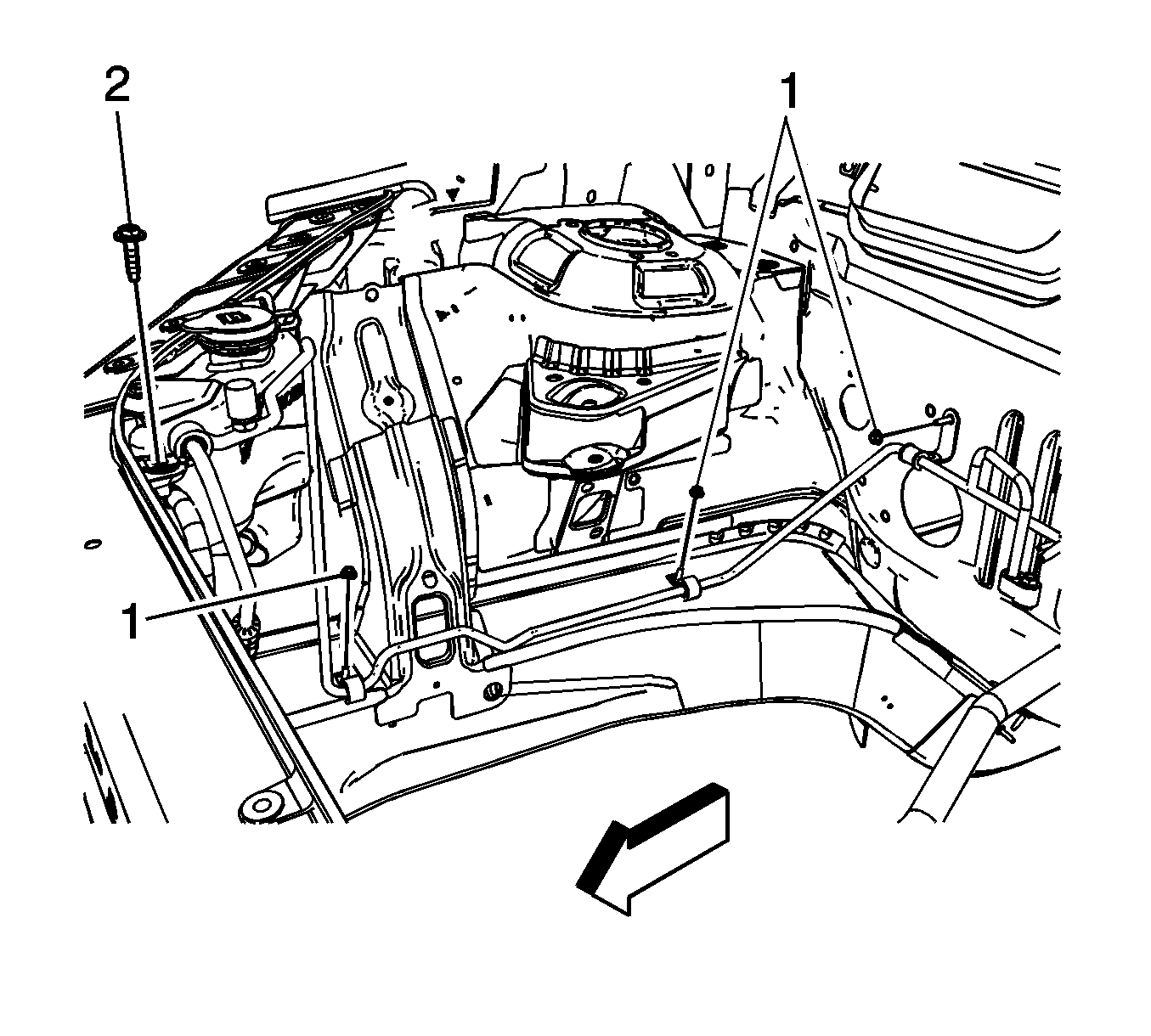
- Remove the air conditioning (A/C) liquid line clamp bolt (2) from the upper radiator support.
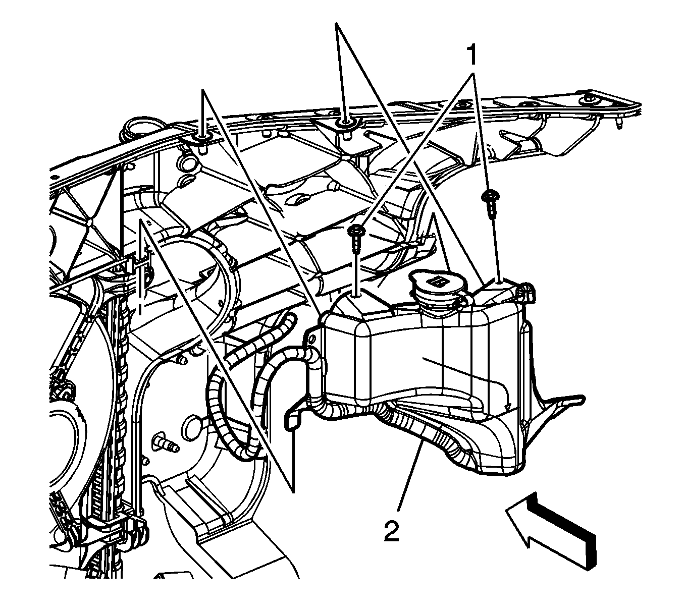
- Remove the coolant recovery reservoir bolts (1).
- Remove the reservoir (2) tabs from the upper radiator support, position the reservoir out of the way.
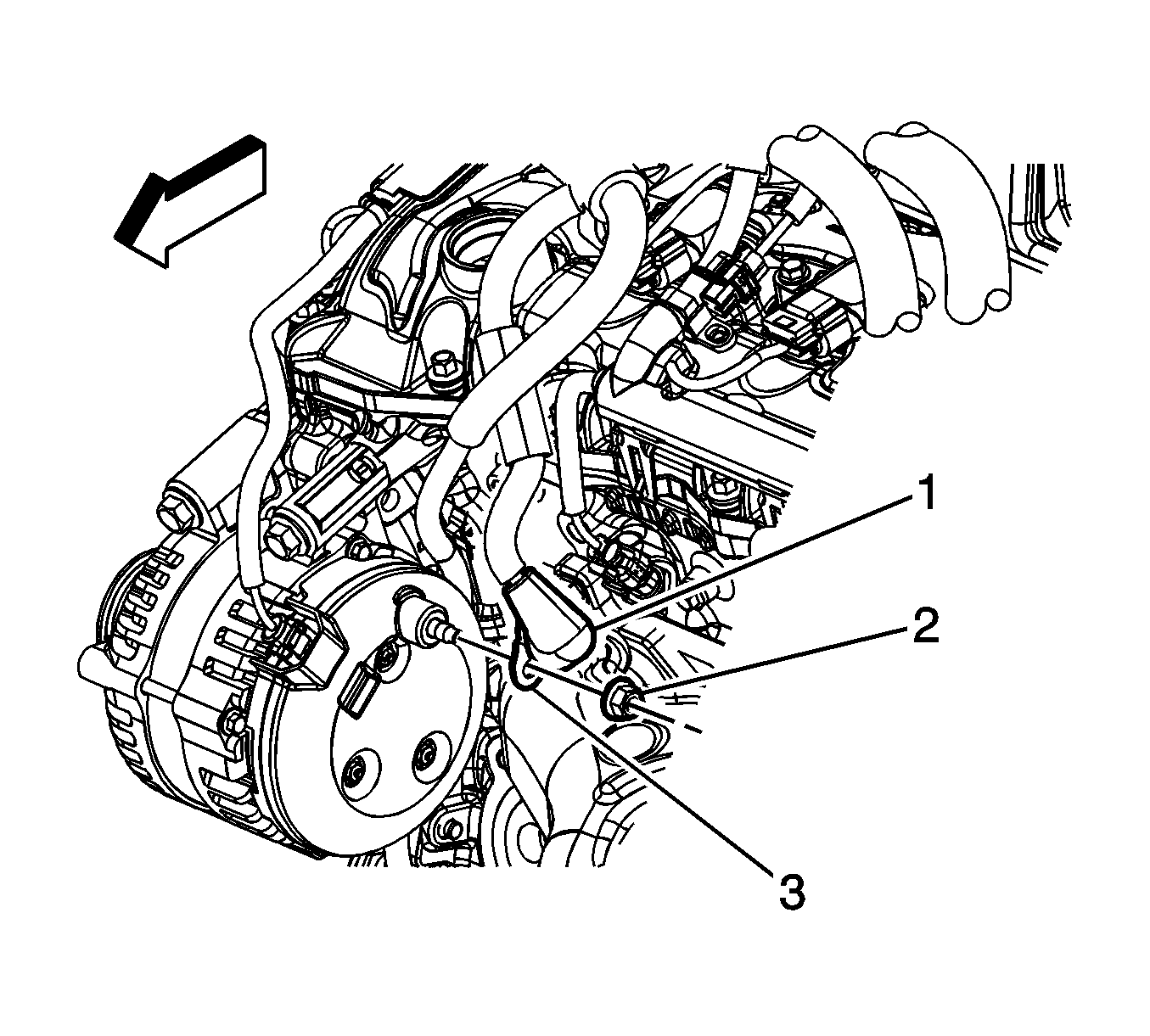
- Reposition the battery positive junction block cable boot (1).
- Remove the battery positive junction block cable to generator nut (2).
- Remove the battery positive junction block cable terminal (3) from the generator stud.
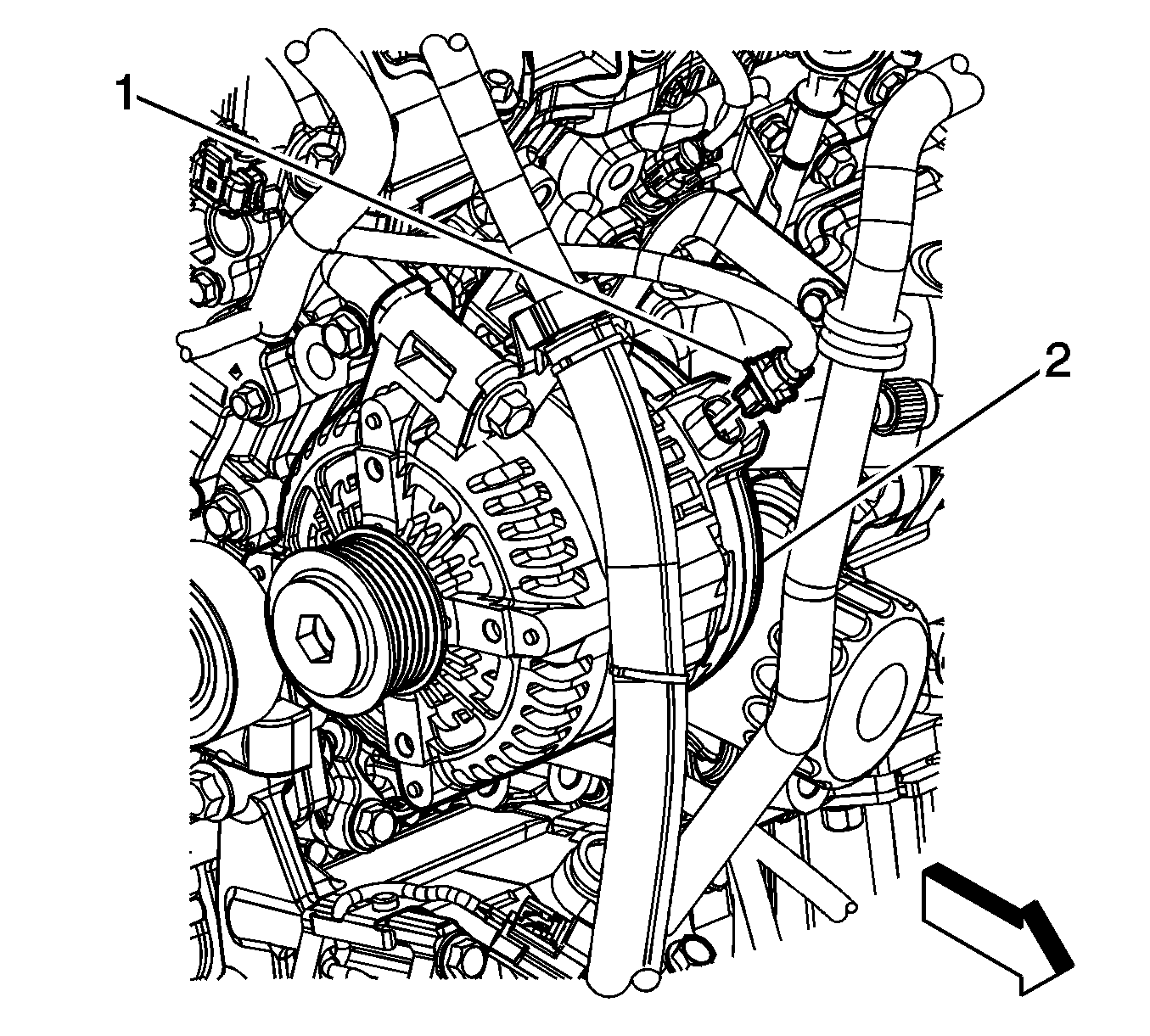
- Disconnect the engine wiring harness electrical connector (1) from the generator (2).
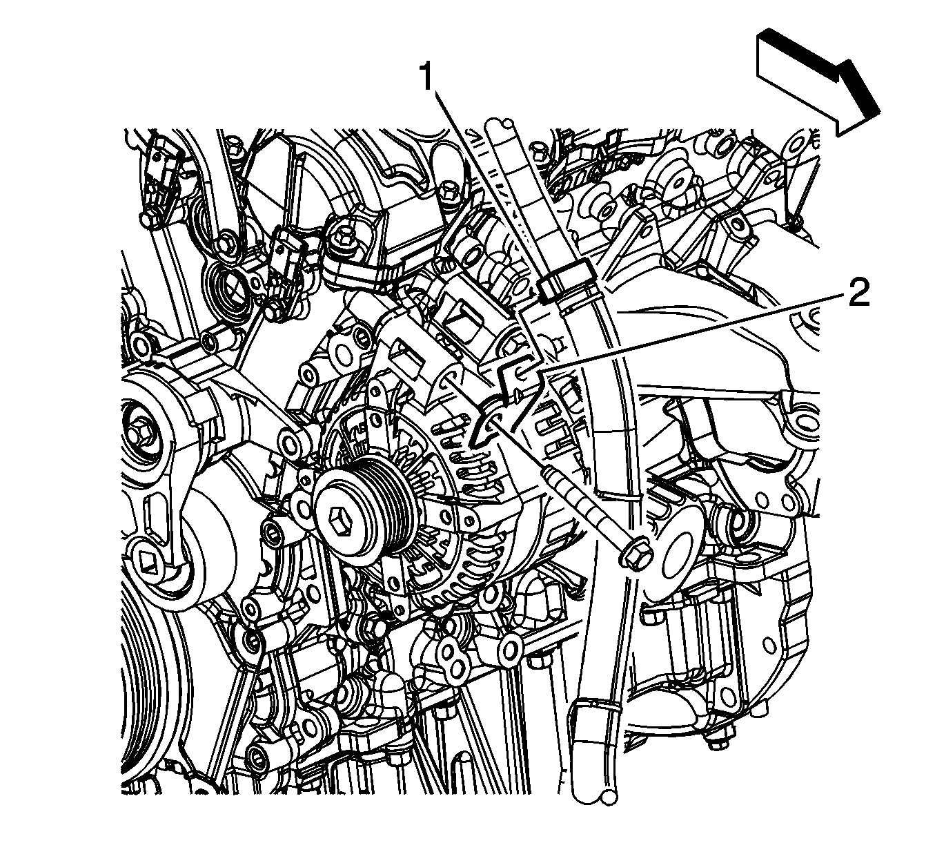
- Remove the power steering reservoir inlet hose clip (1) from the power steering fluid reservoir hose clip bracket (2).
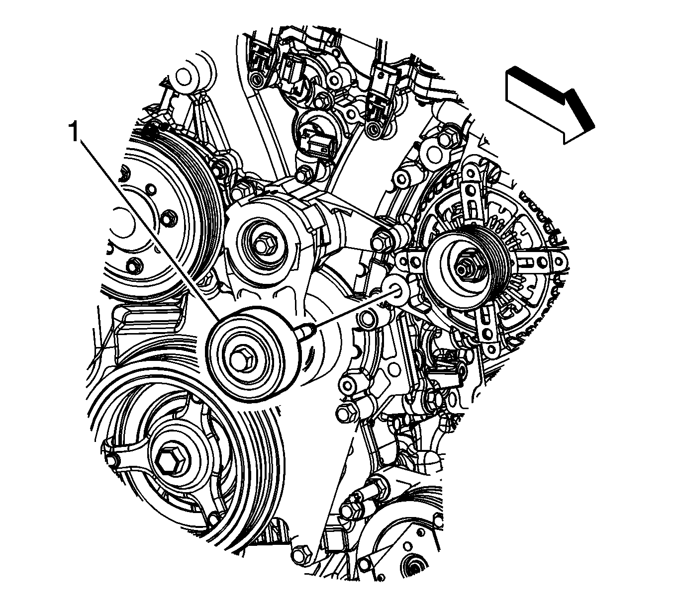
- Loosen the idler pulley (1) bolt and slide the pulley out as far as possible.
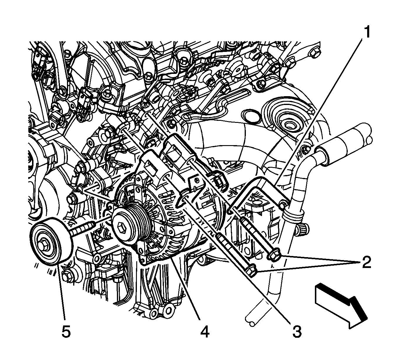
- Remove the generator bolts (2).
- Remove the A/C compressor/evaporator hose bracket (1) from against the generator.
- Remove the power steering fluid reservoir hose clip bracket (3) from against the generator.
- Remove the generator (4) and idler pulley (5) together from the vehicle.
- Remove the idler pulley from the generator.
Installation Procedure
- Install the idler pulley (5) to the generator.
- Install the generator (4) and idler pulley together to the vehicle.
- Install the power steering fluid reservoir hose clip bracket (1) onto one of the generator bolts, and install the bolt finger tight.
- Install the A/C compressor/evaporator hose bracket (2) onto the other generator bolt, and install the bolt finger tight.
- Tighten the idler pulley/generator bolts (2) in the following sequence:
- Install the power steering reservoir inlet hose clip (1) to the power steering fluid reservoir hose clip bracket (2).
- Connect the engine wiring harness electrical connector (1) to the generator.
- Install the battery positive junction block cable terminal (3) to the generator stud.
- Install the battery positive junction block cable to generator nut (2).
- Position the battery positive junction block cable boot (1) over the stud.
- Install the coolant recovery reservoir (2) tabs into the appropriate slots in the upper radiator support .
- Install the coolant recovery reservoir bolts (1).
- Install the A/C liquid line clamp bolt (2) at the upper radiator support.
- Install the engine mount strut bracket. Refer to Engine Mount Strut Bracket Replacement - Right Side .
- Install the fuel injector sight shield. Refer to Fuel Injector Sight Shield Replacement .
- Install the drive belt. Refer to Drive Belt Replacement .
- Connect the negative battery cable. Refer to Battery Negative Cable Disconnection and Connection .

Notice: Refer to Fastener Notice in the Preface section.
| 5.1. | Idler pulley bolt |
| 5.2. | Generator bolts |
Tighten
Tighten the bolts to 50 N·m (37 lb ft).


Tighten
Tighten the nut to 22 N·m (16 lb ft).

Tighten
Tighten the bolts to 5 N·m (44 lb in).

Tighten
Tighten the bolt to 9 N·m (80 lb in).
