For 1990-2009 cars only
Removal Procedure
- Turn the ignition OFF.
- Remove the fuel injector sight shield. Refer to Fuel Injector Sight Shield Replacement.
- Remove the air cleaner outlet duct. Refer to Air Cleaner Outlet Duct Replacement.
- Disconnect the brake booster vacuum hose from the intake manifold.
- Remove the rear positive crankcase ventilation hose. Refer to Positive Crankcase Ventilation Tube Replacement - Rear.
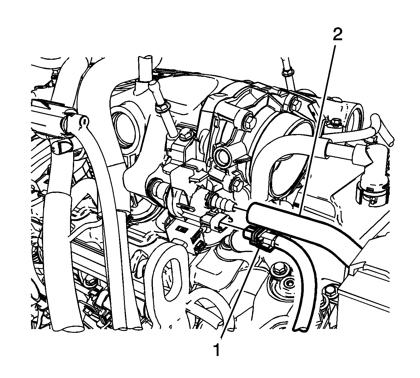
- Disconnect the purge solenoid valve electrical connector (1).
- Disconnect the purge line (2) from the purge solenoid valve.
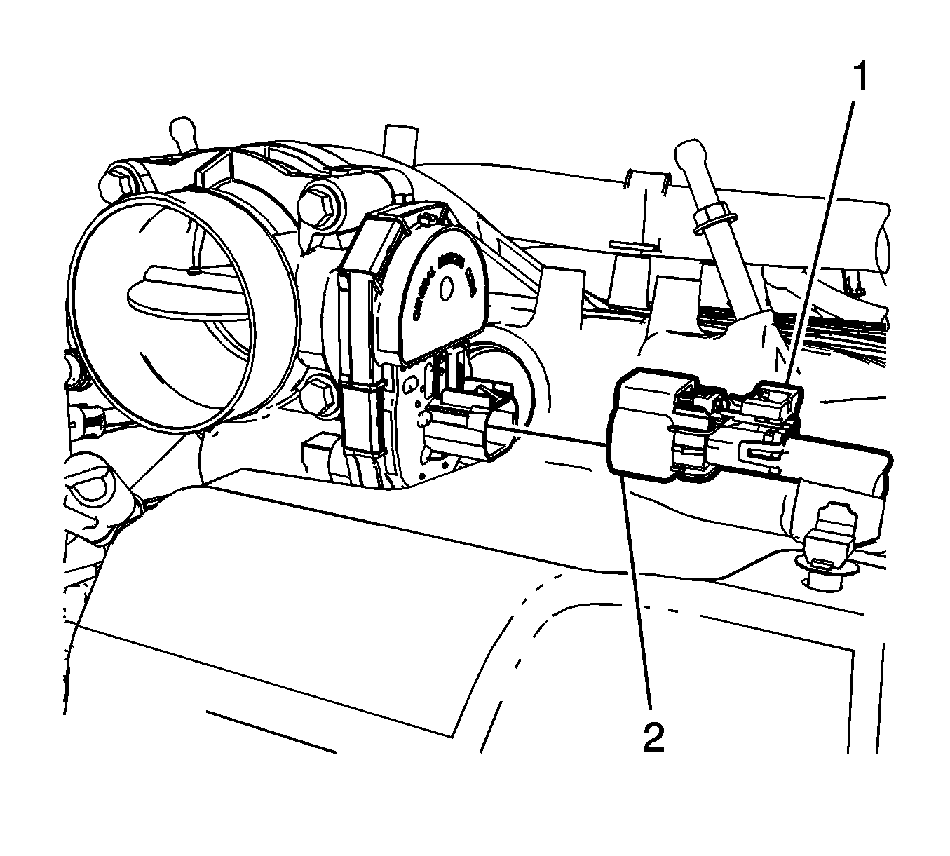
- Remove the electrical connector retainer (1).
- Disconnect the throttle body electrical connector (2).
- Remove the fuel pipe shield. Refer to Fuel Pipe Shield Replacement.
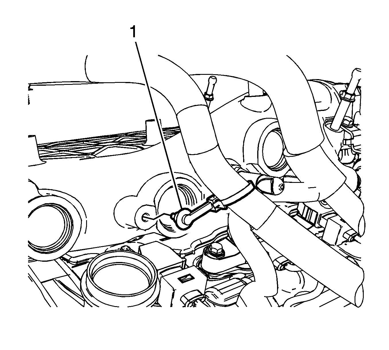
- Remove the engine wiring harness retaining clip (1) from the side of the intake manifold.
- Remove the wiring harness retaining bolt.
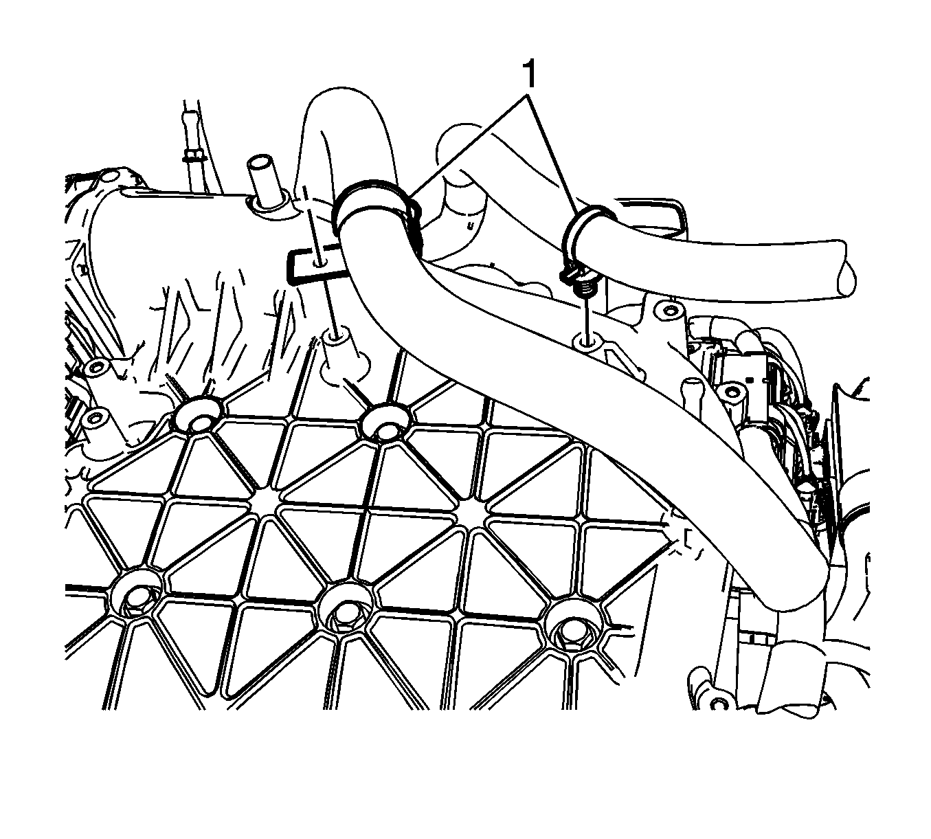
- Remove the engine wiring harness retaining clips (1) from the intake manifold.
- Position the engine wiring harness aside.
- Remove the intake manifold insulator.
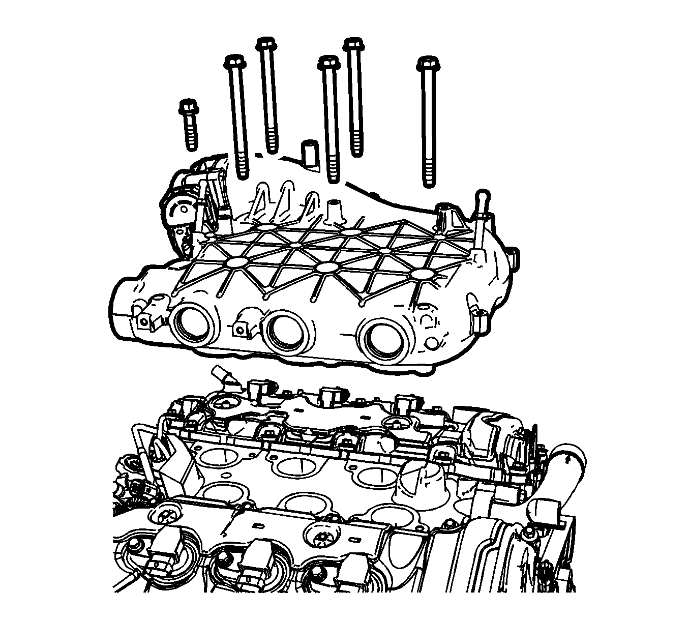
- Remove the intake manifold bolts (1).
- Remove the intake manifold (2) with the throttle body.
- If the intake manifold is being replaced, disassemble the intake manifold. Refer to Intake Manifold Disassemble.
- Clean and inspect the intake manifold. Refer to Intake Manifold Cleaning and Inspection.
Installation Procedure
- If the intake manifold is being replaced, assemble the intake manifold. Refer to Intake Manifold Assemble.
- Install a NEW intake manifold gasket.
- Install the intake manifold (2).
- Install the intake manifold bolts (1) and tighten to 23 N·m (17 lb ft).
- Position the engine wiring harness in place.
- Install the engine wiring harness retaining clips (1) to the intake manifold.
- Install the engine wiring harness retaining clip (1) to the side of the intake manifold.
- Install the fuel pipe shield. Refer to Fuel Pipe Shield Replacement.
- Connect the electrical connector (2) to the throttle body.
- Install the electrical connector retainer (1).
- Connect the purge line (2) to the purge solenoid valve.
- Connect the purge solenoid valve electrical connector (1).
- Install the rear positive crankcase ventilation hose. Refer to Positive Crankcase Ventilation Tube Replacement - Rear.
- Connect the brake booster vacuum hose to the intake manifold.
- Install the air cleaner outlet duct. Refer to Air Cleaner Outlet Duct Replacement.
- Install the fuel injector sight shield. Refer to Fuel Injector Sight Shield Replacement.

Caution: Refer to Fastener Caution in the Preface section.
Note: Tighten the intake manifold bolts in a circular pattern starting at the center (long bolts) and moving outward.


Caution: Ensure proper engagement of the wiring harness connector. The wiring harness connector must be installed straight onto the component connector and firmly seated. Visually inspect the connector to ensure that the connector latches are engaged and locked. Any damage to the connector or wiring must be repaired. Failure to follow this procedure can lead to an intermittent electrical connection, driveability concerns, and/or wiring harness or wiring harness connector damage or failure.

