For 1990-2009 cars only
Removal Procedure
- Relieve the fuel system pressure. Refer to Fuel Pressure Relief.
- Remove the fuel injector sight shield. Refer to Fuel Injector Sight Shield Replacement.
- Remove air cleaner assembly. Refer to Fuel Injector Sight Shield Replacement.
- Disconnect the brake pressure modulator valve from the body to provide clearance for the fuel pipes. Refer to Brake Pressure Modulator Valve Replacement
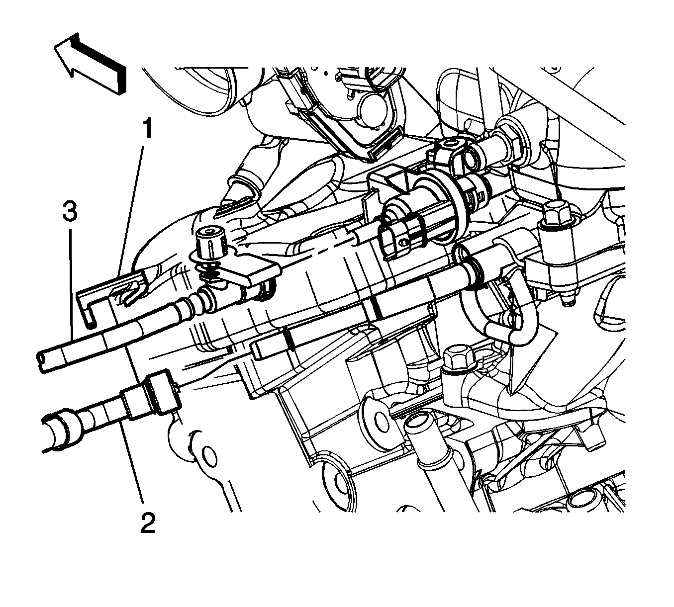
- Disconnect the fuel feed pipe (2) quick connect fitting from the fuel rail. Refer to Metal Collar Quick Connect Fitting Service.
- Disconnect the evaporative emission (EVAP) pipe (3) quick connect fitting from the EVAP purge solenoid. Refer to Plastic Collar Quick Connect Fitting Service.
- Cap the fuel rail and the EVAP purge solenoid in order to prevent possible fuel and/or EVAP system contamination.
- Raise and support the vehicle. Refer to Lifting and Jacking the Vehicle.
- Remove the intermediate steering shaft. Refer to Intermediate Steering Shaft Replacement.
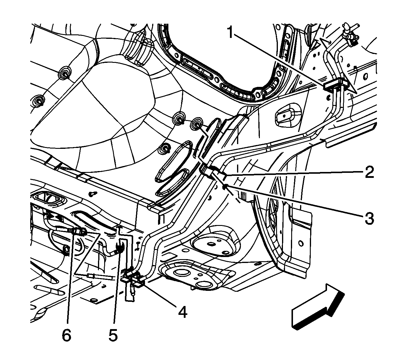
- Disconnect the fuel pump fuel feed pipe quick connect fitting (6) from the chassis fuel feed pipe. Refer to Plastic Collar Quick Connect Fitting Service.
- Disconnect the EVAP canister vent front pipe quick connect fitting (5) from the chassis EVAP pipe. Refer to Plastic Collar Quick Connect Fitting Service.
- Remove the fuel feed/EVAP pipe assembly clip (1) from the body.
- Remove the fuel feed/EVAP pipe assembly clip nut (3) and clip (2) from the stud.
- Loosen the fuel feed/EVAP pipe clip (4) bolt, and remove the fuel feed/EVAP pipe assembly from the vehicle.
- Mark the location of the retainers on the new pipes and remove the plastic retainers from the old pipes using a soapy solution.


Installation Procedure
- Position the fuel feed and EVAP pipes to the vehicle individually, and install the plastic retainers to the marked locations. Tighten the fuel feed/EVAP pipe clip (4) bolt to 8 N·m (71 lb in).
- Install the fuel feed/EVAP pipe clip (2) and nut (3) to the stud and tighten to 9 N·m (80 lb in).
- Install the fuel feed/EVAP pipe clip (1) to the body.
- Connect the EVAP canister vent front pipe quick connect fitting (5) to the chassis EVAP pipe. Refer to Plastic Collar Quick Connect Fitting Service.
- Connect the fuel pump fuel feed pipe quick connect fitting (6) to the chassis fuel feed pipe. Refer to Plastic Collar Quick Connect Fitting Service.
- Install the intermediate steering shaft. Refer to Intermediate Steering Shaft Replacement.
- Remove the caps from the fuel rail and the EVAP purge solenoid.
- Connect the EVAP pipe (3) quick connect fitting to the EVAP purge solenoid. Refer to Plastic Collar Quick Connect Fitting Service.
- Connect the fuel feed pipe (2) quick connect fitting to the fuel rail. Refer to Metal Collar Quick Connect Fitting Service.
- Tighten the fuel fill cap.
- Use the following procedure in order to inspect for leaks:
- Reconnect the brake pressure modulator valve from the body to provide clearance for the fuel pipes. Refer to Brake Pressure Modulator Valve Replacement
- Install the air cleaner assembly. Refer to Fuel Injector Sight Shield Replacement.
- Install the fuel injector sight shield. Refer to Fuel Injector Sight Shield Replacement.
Caution: Refer to Fastener Caution in the Preface section.


| • | Turn the ignition ON, with the engine OFF, for 2 seconds. |
| • | Turn the ignition OFF for 10 seconds. |
| • | Turn the ignition ON, with the engine OFF. |
| • | Inspect for fuel leaks. |
