| Table 1: | ISS Removal |
| Table 2: | Low and Reverse Clutch Piston Removal |
| Table 3: | 2-6 Clutch Piston Removal |
| Table 4: | Clean and Inspect |
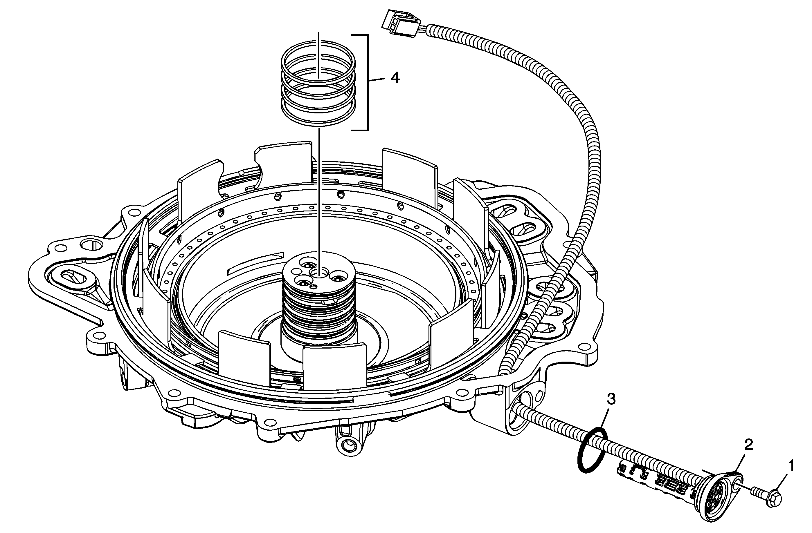
ISS Removal

Callout | Component Name |
|---|---|
1 | A/Trans Input Speed Sensor Bolt M6 x 25 |
2 | A/Trans Input Speed Sensor |
3 | A/Trans Input Speed Sensor Seal Tip |
4 | 3-5 Reverse and 4-5-6 Clutch Fluid Seal Ring Tip |
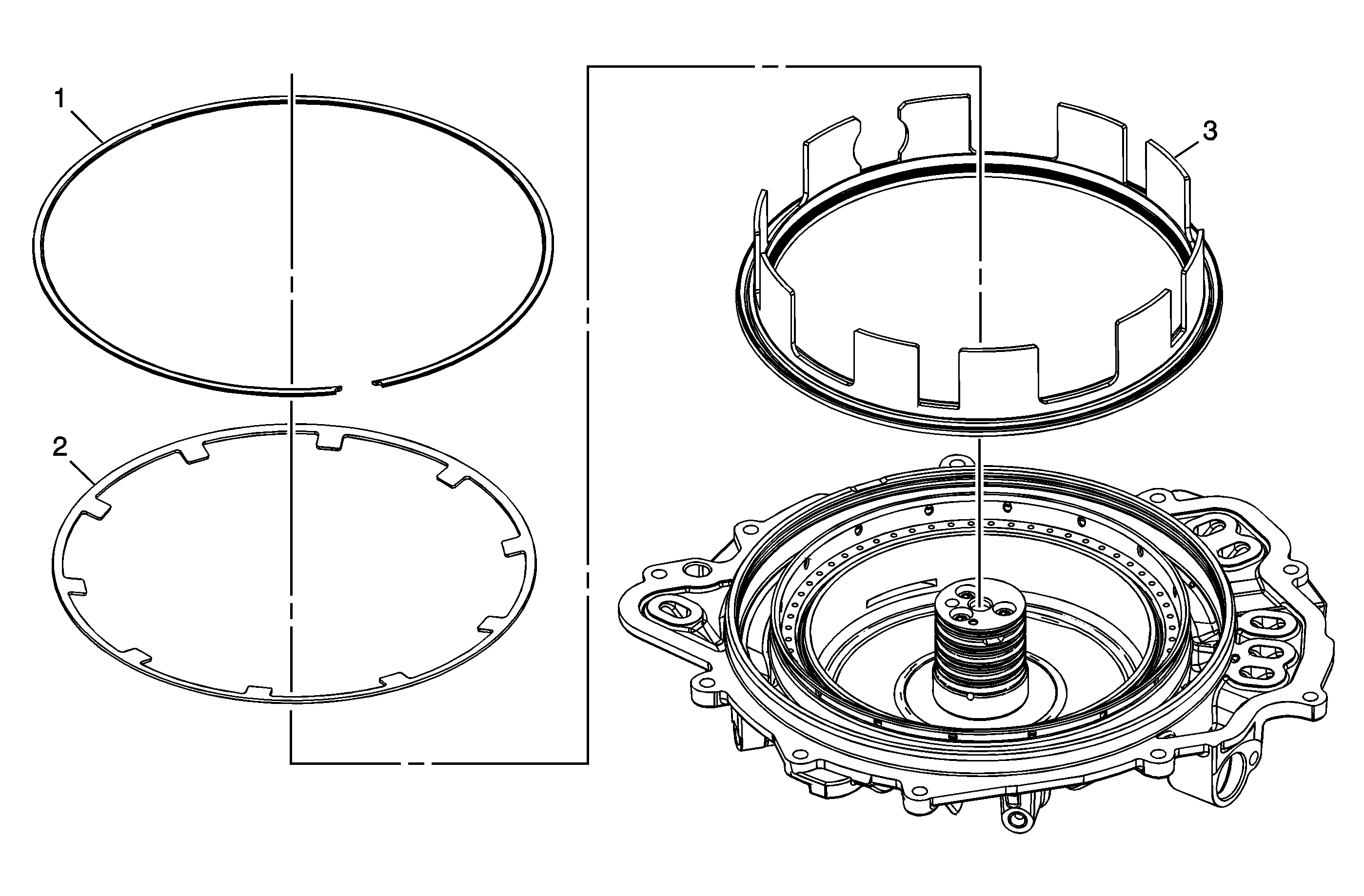
Low and Reverse Clutch Piston Removal

Callout | Component Name |
|---|---|
1 | Low and Reverse Clutch Spring Retaining Ring |
2 | Low and Reverse Clutch Spring |
3 | Low and Reverse Clutch Piston Assembly Tip |
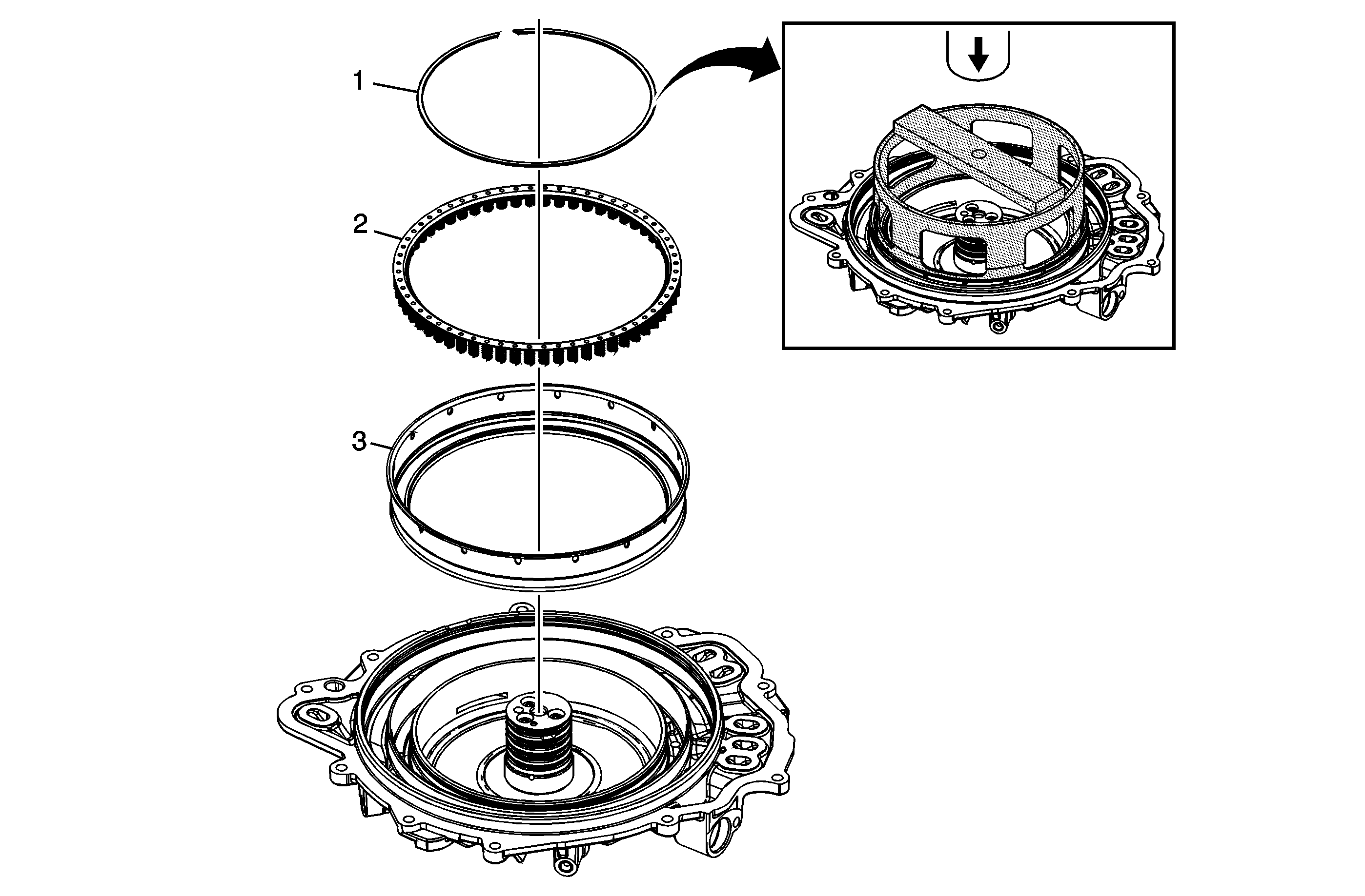
2-6 Clutch Piston Removal

Callout | Component Name |
|---|---|
1 | 2-6 Clutch Spring Retaining Ring Special ToolsJ-46632 Spring Compressor For equivalent regional tools, refer to Special Tools. |
2 | 2-6 Clutch Spring Assembly |
3 | 2-6 Clutch Piston Tip |
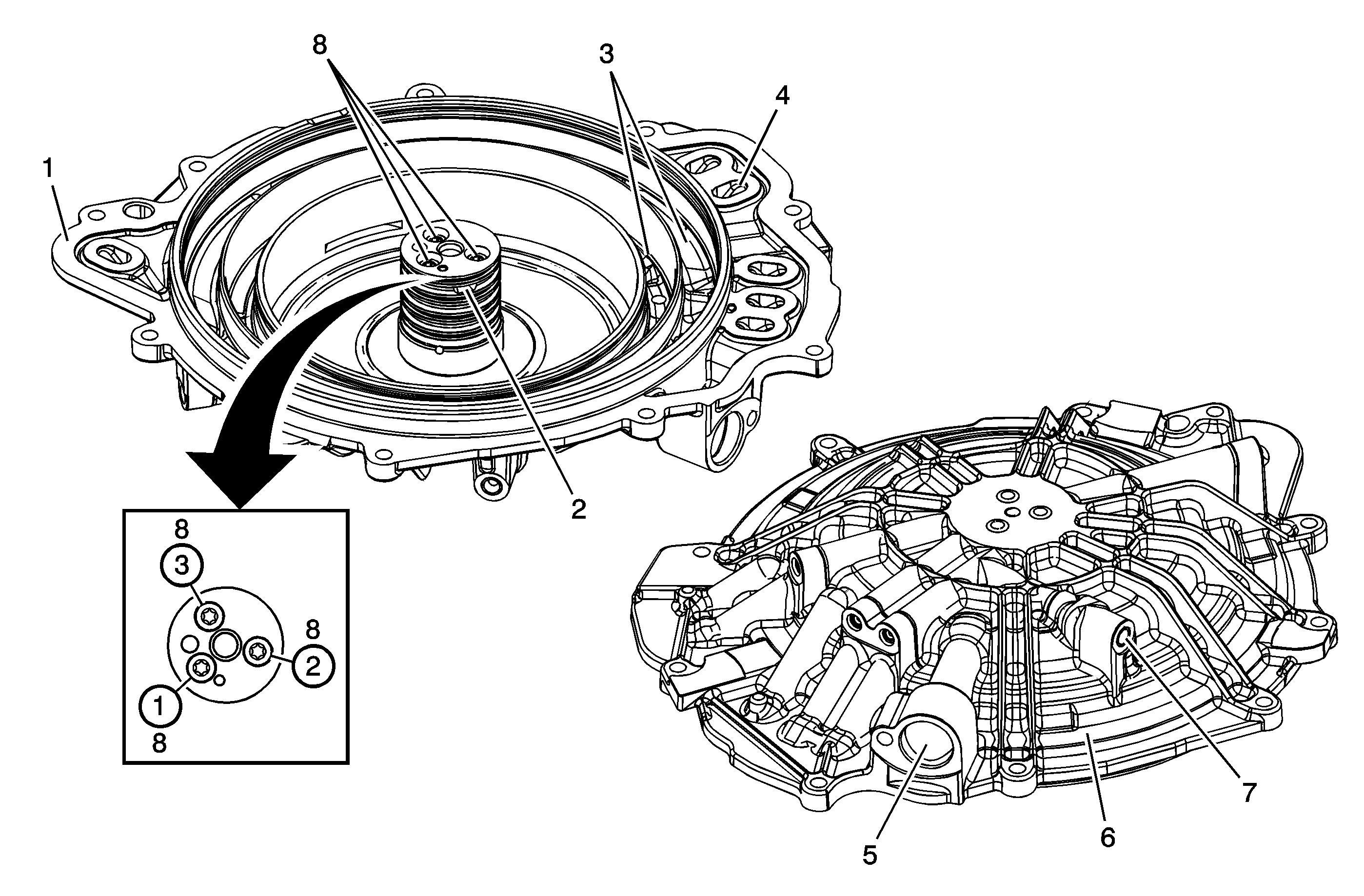
Clean and Inspect

Callout | Component Name |
|---|---|
|
Caution: After cleaning the transmission components, allow to air dry. Do not use cloth or paper towels in order to dry any transmission components. Lint from the towels can cause component failure. Caution: Do not reuse cleaning solvents. Previously used solvents may deposit sediment which may damage the component. Preliminary Procedures
| |
1 | Gasket Sealing Surface |
2 | Fluid Passages |
3 | Piston Bores |
4 | Cover to Case Passages |
5 | A/Trans Input Speed Sensor Assembly Bore |
6 | Cover Casting |
7 | Passage Cup Plugs |
8 | Input Shaft Support Bolts ProcedureTightened bolts in sequence. Tighten12 N·m (106 lb in). |
