Removal Procedure
Important: If you are replacing one or both of the FRONT frame insulators AND one or both of the REAR frame insulators, you will need to follow the instructions for frame replacement. Refer to Frame Replacement . However, it will NOT be necessary to disconnect the tie rod ends, the lower ball joints or the wheel speed sensor wiring harnesses as the frame does not need to be completely removed from the vehicle in order to replace the frame insulators.
- Raise and support the vehicle. Refer to Lifting and Jacking the Vehicle in General Information.
- Install a utility stand to the frame between the left and right frame insulators.
- If you are replacing either of the frame REAR insulators, disconnect the intermediate shaft from the steering gear stub shaft. Refer to Lower/Upper Intermediate Steering Shaft Replacement in Power Steering System.
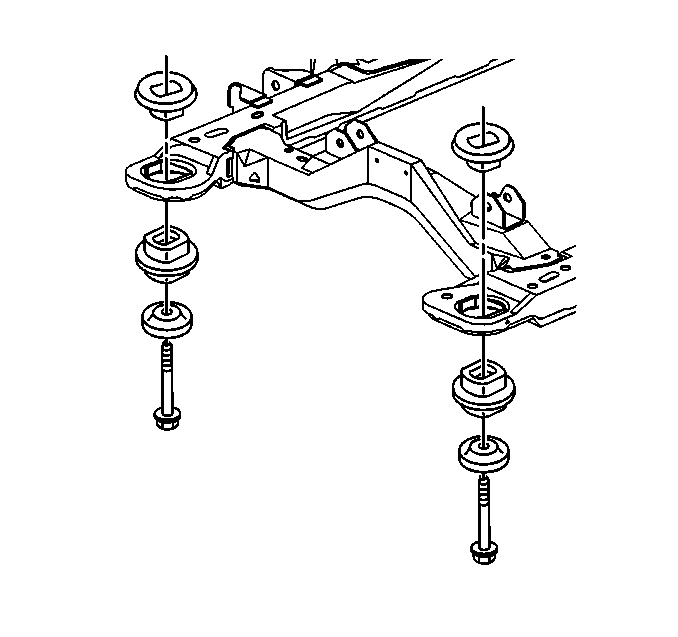
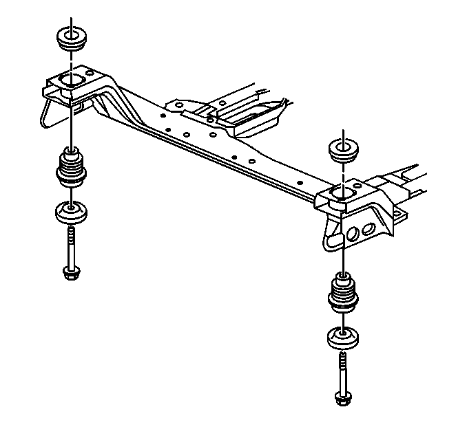
- Remove and DISCARD the frame bolt of the frame insulator that you are replacing.
- Remove and DISCARD the opposite side frame bolt (side to side).
- Use the utility stand in order to lower the frame ONLY far enough to remove the frame insulator.
- Remove the frame upper insulator.
- Remove the frame lower insulator.

Caution: Failure to disconnect the intermediate shaft from the rack and pinion stub shaft can result in damage to the steering gear and/or intermediate shaft. This damage can cause loss of steering control which could result in personal injury.

Important: Do not loosen or remove the remaining frame bolts.
Notice: Ensure that lowering the frame does not interfere with the bumper fascia or fascia damage may result.
Notice: Some frames are constructed of heat-treated steel. Do not weld or drill these frames. The use of heat in excess of 606°C (1200°F) can weaken, cause distortion, and change the characteristics of the steel.
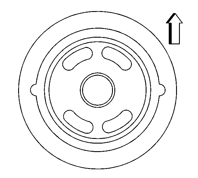
Important: Note the orientation of the frame lower insulator to the frame.
Installation Procedure
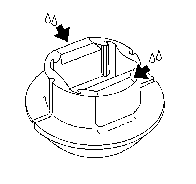
- Apply a thin layer of GM P/N 12345884 (or equivalent) to the frame insulators.
- Install the frame lower insulators to the frame.
- Install the frame upper insulators.
- Use the utility stand in order to raise the frame.
- Insert two 19 mm (0.75 in) diameter X 203 mm (8.0 in) long pins or drill bits into the frame right side alignment holes in order to align the frame.
- Install the NEW frame bolts.
- Remove the utility stand.
- If you are replacing either of the frame REAR insulators, connect the intermediate shaft to the steering gear stub shaft. Refer to Lower/Upper Intermediate Steering Shaft Replacement in Power Steering System.
- Lower the vehicle.
- Inspect the front wheel alignment and adjust the toe angle if necessary. Refer to Wheel Alignment Measurement .


Important: Ensure that the frame lower insulators are installed with the center voids inline with the front to rear portion of the frame.

Important: Ensure that the alignment pins remain installed during the frame installation.

Notice: Use the correct fastener in the correct location. Replacement fasteners must be the correct part number for that application. Fasteners requiring replacement or fasteners requiring the use of thread locking compound or sealant are identified in the service procedure. Do not use paints, lubricants, or corrosion inhibitors on fasteners or fastener joint surfaces unless specified. These coatings affect fastener torque and joint clamping force and may damage the fastener. Use the correct tightening sequence and specifications when installing fasteners in order to avoid damage to parts and systems.
Tighten
Tighten the NEW frame FRONT bolts to 150 N·m (111 lb ft).
Tighten
Tighten the NEW frame REAR bolts to 165 N·m (122 lb ft).
