A/C Compressor Growl/Whine Noise After Vehicle Accelerates From a Stop (Check A/C System Charge, Compressor Attaching Bolts and Line Routing Until a Permanent Solution Is Available)

| Subject: | A/C Compressor Growl/Whine Noise After Vehicle Accelerates From A Stop (Check A/C System Charge, Compressor Attaching Bolts and Line Routing Until A Permanent Solution Is Available) |
| Models: | 2005-2006 Buick Allure (Canada Only), LaCrosse |
| 2005 Chevrolet Impala, Monte Carlo |
| 2004-2006 Pontiac Grand Prix |
| with 3.8L V6 Engine (VINs 2, K-- RPOs L26, L36) |
This bulletin is being revised to add the 2006 model year for the Buick and Pontiac vehicles. Please discard Advanced Service Information Bulletin Number 05-01-38-015A (Section 01 -- HVAC).
Condition
Some customers may comment on an air conditioning (A/C) compressor growl or whine noise after the vehicle accelerates from a stop. The noise is heard until the engine reaches approximately 2200 RPMs or the vehicle speed reaches 56-64 km/h (35-40 mph).
Correction
Do This | Don't Do This |
|---|---|
Follow the diagnostic steps listed below. | Do not replace the A/C compressor. |
Technicians are to check for the following conditions and repair as necessary:
- Perform the Air Conditioning System Performance Test to verify that the A/C system is operating properly and has a full refrigerant charge. Refer to the Air Conditioning (A/C) System Performance Test procedure in the HVAC section of SI. Be sure to attach the "charge summary/snapshot" printout to the shop's copy of the repair order. Refer to Corporate Bulletin Number 05-01-38-008A for more information about this warranty requirement.
- Check that all the A/C compressor attaching bolts are properly tightened.
- Check for A/C line ground outs at the following locations. Use the following steps to reposition or reroute the components as necessary:
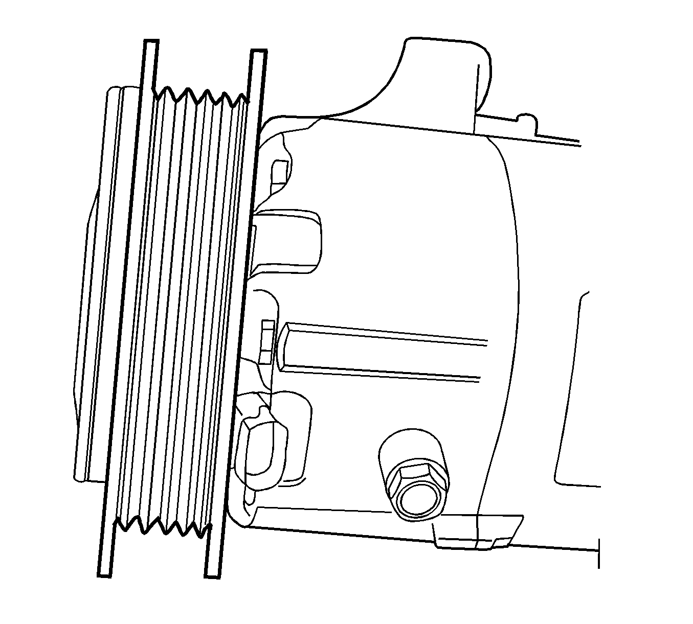
- On 2005 Pontiac Grand Prix vehicles built after January 1, 2005 and all 2005 Buick Allure/LaCrosse vehicles, check to see if the A/C compressor has an inertia pulley. Figure 1 shows a compressor with a non-inertia pulley. Figure 2 shows a compressor with an inertia pulley. If the A/C compressor has been replaced during a previous repair then the compressor currently on the vehicle may not have an inertia pulley. If the A/C compressor does not have an inertia pulley, then install an A/C Clutch Assembly, P/N 89018605.
Important: Not all models may be exactly as illustrated below but the line routing and component locations will be similar.
| 3.1. | Remove the fuel injector sight shield. Refer to the Fuel Injector Sight Shield Replacement procedure in the Engine Mechanical section of SI. |
| 3.2. | Remove the air cleaner intake duct. Refer to the Air Cleaner Intake Duct Replacement procedure in the Engine Controls section of SI. |
| 3.3. | Remove the air cleaner assembly. Refer to the Air Cleaner Assembly Replacement procedure in the Engine Mechanical section of SI. |
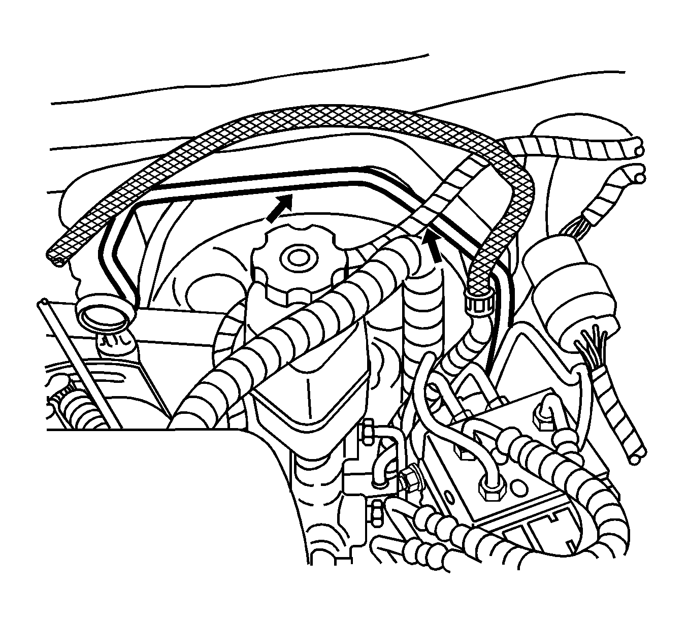
| 3.4. | Check the A/C line routing around the brake booster assembly. On Buick and Pontiac vehicles, the A/C line is routed above the brake booster assembly. On Chevrolet vehicles, the A/C line is routed under the brake booster assembly and may not have this condition. Reposition the A/C line if it is making contact with any part of the brake booster. Be sure to hold the lines near the evaporator core with one hand as the lines are repositioned to prevent excessive torque being applied to the evaporator core line connection. |
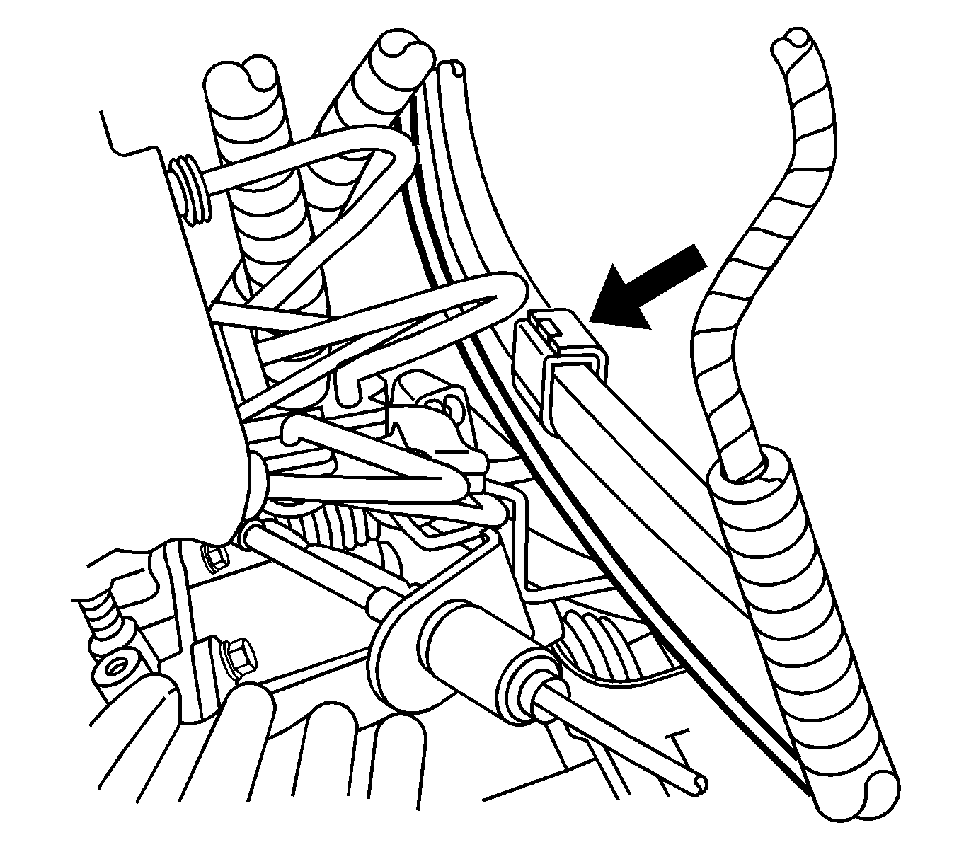
| 3.5. | Check the A/C line retainer that is attached to the left strut tower. Make sure that both lines are securely held in place by the retainer as shown by the arrow in the illustration above. The hood release cable, represented by the heavy lines in the illustration above, should be routed inboard of the A/C lines. You may find that the hood release cable has been routed incorrectly between the A/C lines and the strut tower. Reposition the hood release cable inboard of the A/C lines and secure it away from the A/C lines with tie straps as necessary. The illustration above represents a vehicle not equipped with antilock brakes (ABS). On vehicles equipped with ABS, the A/C line retainer and hood release cable are located below the ABS module. |
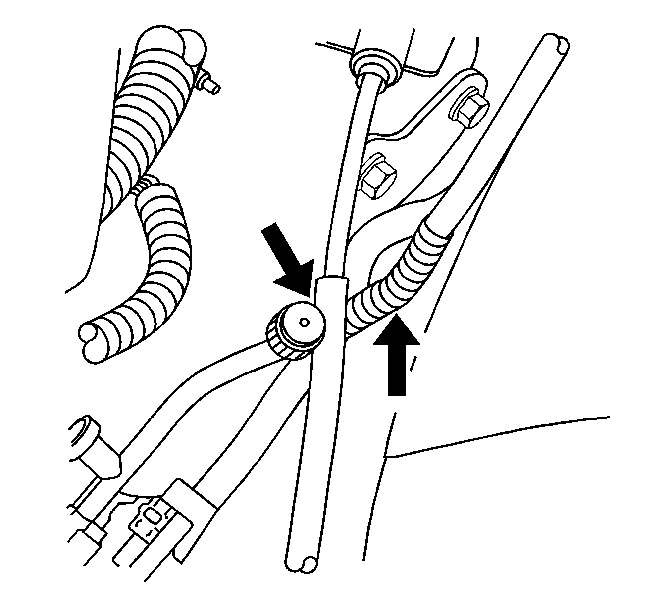
| 3.6. | Check the routing of the transmission shift cable and the A/C liquid line near the high side gauge port. The transmission shift cable should not make contact with the liquid line. The liquid line should not make contact with the body . Reposition the liquid line and the shift cable as necessary. Secure the shift cable with tie straps as required. |
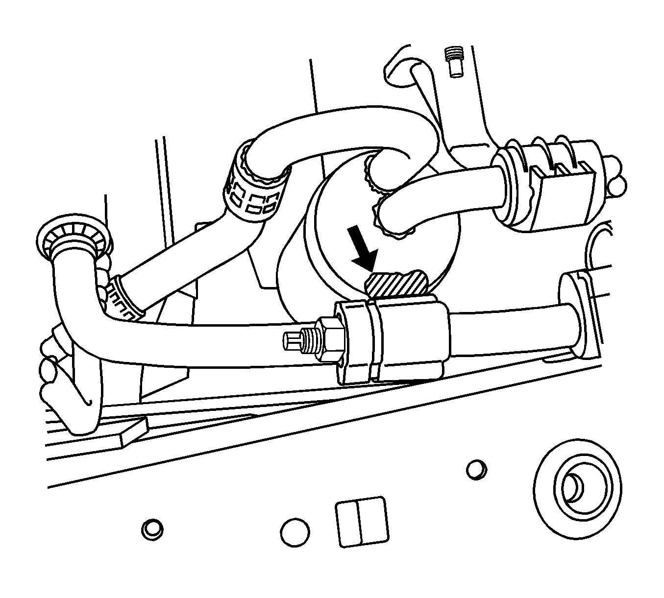
| 3.7. | Check the routing of the compressor inlet pipe above the receiver dehydrator. The line should not contact the receiver dehydrator. Reposition the line away from the receiver dehydrator if necessary. |
| 3.8. | Check that the rubber grommet around the A/C compressor inlet pipe is properly positioned in the bracket that is attached to the left frame rail. Reposition the rubber grommet if necessary. |
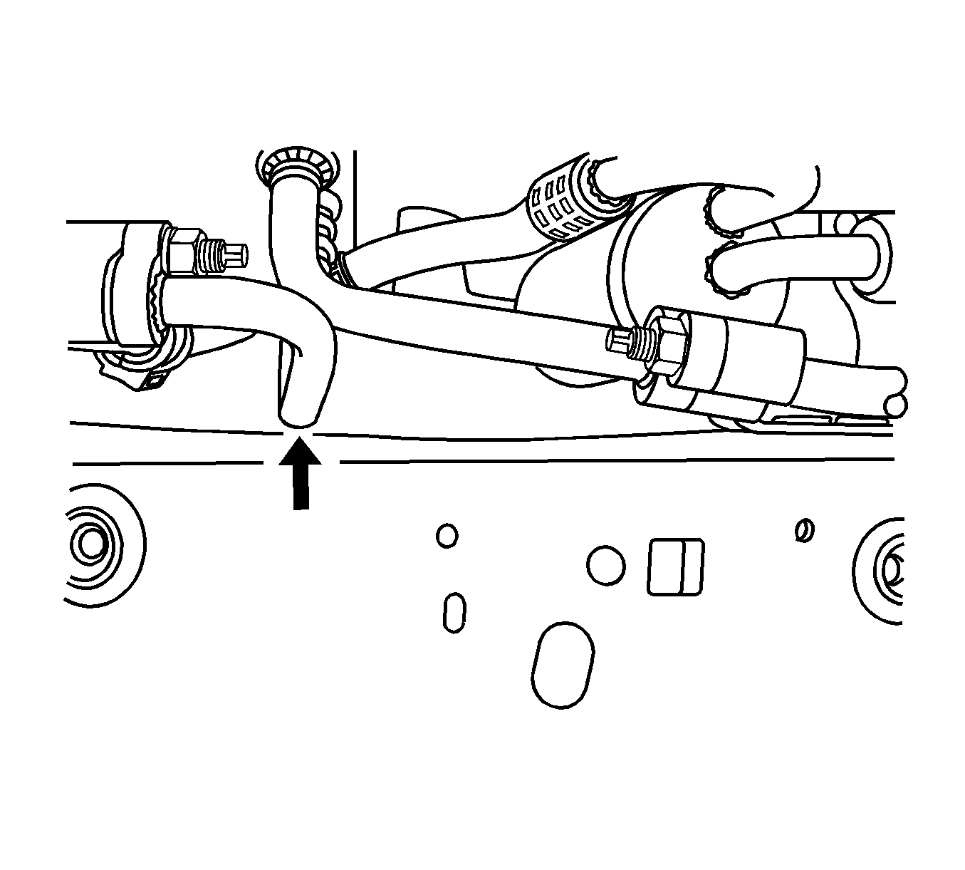
| 3.9. | Check the routing of the condenser inlet pipe as shown by the arrow in the illustration above. It should not contact the frame rail. Check the routing of the hood release cable in this area. It should not contact the condenser inlet pipe. Reposition the hood release cable away from the condenser inlet pipe and secure it with tie straps if necessary. |
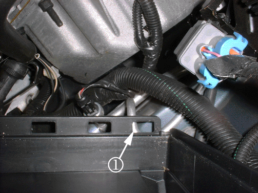
| 3.10. | Check the routing of the A/C pipe (1) under the rear lower corner of the air cleaner. Reposition the line away from the air cleaner if necessary. |
| 3.11. | Install the air cleaner assembly. Refer to the Air Cleaner Assembly Replacement procedure in the Engine Mechanical section of SI. |
| 3.12. | Install the air cleaner intake duct. Refer to the Air Cleaner Intake Duct Replacement procedure in the Engine Controls section of SI. |
| 3.13. | Install the fuel injector sight shield. Refer to the Fuel Injector Site Shield Replacement procedure in the Engine Mechanical section of SI. |
Figure 1
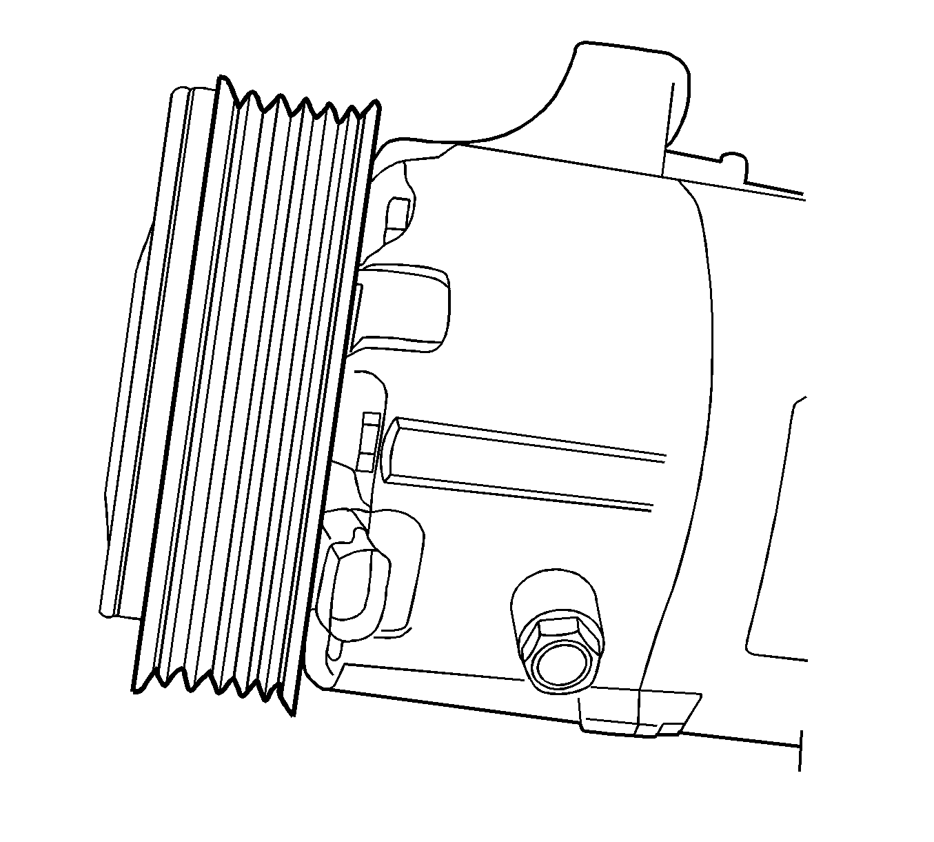
Figure 2
Engineering is currently investigating a permanent solution. Once the solution is available, this bulletin will be revised.
Parts Information
Important: If the A/C compressor is replaced for another specific reason and the replacement compressor does not have an inertia pulley, then be sure to transfer the inertia pulley to the new compressor before installing it on the vehicle.
Part Number | Description | Qty |
|---|---|---|
89018605 | Clutch ASM, A/C | 1 |
Warranty Information
For vehicles repaired under warranty, use:
Labor Operation | Description | Labor Time |
|---|---|---|
D4240 | Clutch Plate And Hub Assembly, Compressor - Replace | Use Published Labor Operation Time |
D4450 | A/C System - Analyze | |
Add | To Recover and Recharge A/C System | |
D9715* | Reposition A/C Lines, Hood Release And Shift Cables | 0.4 hr |
*This is a unique labor operation number for bulletin use only. This number will not be published in the Labor Time Guide. | ||
