Tools Required
| • | J 42640 Steering Column Anti-Rotation Pin |
| • | EN 46114 Engine Lift Brackets |
Removal Procedure
- Center the steering wheel.
- Turn the ignition OFF.
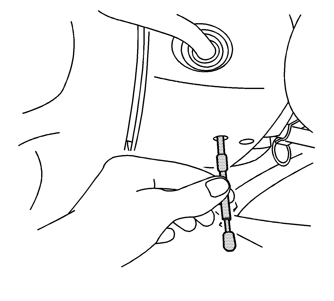
- Install the J 42640 to the steering column.
- Disconnect the battery negative cable from the battery and the body. Refer to Battery Positive Cable Replacement .
- Disconnect the battery positive cable from the battery and the underhood electrical center. Refer to Battery Positive Cable Replacement .
- Position and secure the battery cables to the engine.
- Remove the battery. Refer to Battery Replacement .
- Remove the fuel injector sight shield. Refer to Fuel Injector Sight Shield Replacement .
- Remove the air cleaner duct. Refer to Air Cleaner Inlet Duct Replacement .
- Drain the cooling system. Refer to Cooling System Draining and Filling .
- Disconnect the overflow hose.
- Position and secure the overflow hose to the engine.
- Disconnect the heater hoses from the heater core. Refer to Heater Inlet Hose Replacement and Heater Outlet Hose Replacement .
- Disconnect the purge line (3) from the purge solenoid.
- Disconnect the fuel pipe (2) from the fuel rail. Refer to Metal Collar Quick Connect Fitting Service .
- Evacuate the air conditioning system. Refer to Refrigerant Recovery and Recharging .
- Remove the A/C lines from the A/C compressor. Refer to Compressor Hose Assembly Replacement .
- Disconnect the brake booster check valve and vacuum hose (1) from the brake booster (2).
- Disconnect the brake fluid level switch electrical connector from the master cylinder.
- Disconnect the mass air flow sensor electrical connector.
- Unlock and disconnect the instrument panel (I/P) electrical connector from the engine.
- Disconnect the engine module wiring harness connectors.
- Disconnect the wiring harness from the transmission control module (TCM). Refer to Transmission Control Module Replacement .
- Remove the master cylinder and reposition and secure the master cylinder to the engine.
- Relieve the fuel system pressure. Refer to Fuel Pressure Relief .
- Raise and support the vehicle. Refer to Lifting and Jacking the Vehicle .
- Remove the catalytic converter. Refer to Catalytic Converter Replacement .
- Remove the air deflector.
- Disconnect the left front brake pipe retainer with the brake pipe.
- Remove the right front brake pipe from the brake pipe.
- Disconnect the rear brake pipes (two center pipes) from the BPMV. Refer to Electronic Brake Control Module Replacement .
- Remove the front tire and wheel assemblies. Refer to Tire and Wheel Removal and Installation .
- Remove the intermediate steering shaft. Refer to Intermediate Steering Shaft Replacement .
- Disconnect the transmission shift linkage from the transmission. Refer to Range Selector Lever Cable Replacement .
- Remove the right and left shock module upper mounting bolts. Refer to Strut Assembly Replacement .
- Raise the vehicle enough to place a suitable lift table under the engine, transmission, front frame and front suspension assembly.
- Position a suitable powertrain and/or engine lift table below the frame, engine and transmission.
- Raise the lift table and/or lower the vehicle to support the frame, engine and transmission.
- Remove the transmission brace to underbody bolts. Refer to Transmission Brace Replacement .
- Remove the front frame bolts.
- With the aid of an assistant, lower the table and/or raise the vehicle to remove the engine, transmission, front frame and front suspension assembly from the vehicle.
- Disconnect the engine control module (ECM) electrical connector. Refer to Engine Control Module Replacement .
- Remove the thermostat housing with the heater pipes, heater hoses and surge tank outlet hose. Refer to Engine Coolant Thermostat Housing Replacement .
- Remove the starter motor. Refer to Starter Motor Replacement .
- Remove the heated oxygen sensor (HO2S) connectors.
- Remove the engine wiring harness and related components. Refer to Engine Wiring Harness Assembly Removal .
- Disconnect the transmission oil cooler (TOC) pipes from the engine, radiator and the transmission. Refer to Automatic Transmission Oil Cooler Hose Replacement .
- Disconnect the radiator hoses from the water outlet housing and the coolant inlet pipe.
- Cap and plug the power steering hoses and pipes in order to prevent fluid loss and contamination.
- Remove the radiator hoses. Refer to Radiator Inlet Hose Replacement and Radiator Outlet Hose Replacement .
- Install the EN 46114 to the engine.
- Connect a floor crane to the engine lift brackets and raise the floor crane to partially support the engine.
- Position a second powertrain lift table below the transmission.
- Remove the transmission. Refer to Transmission Replacement .
- Remove the drive belts. Refer to Drive Belt Removal .
- Remove the drive belt tensioner. Refer to Drive Belt Tensioner Removal .
- Remove the idler pulley. Refer to Drive Belt Idler Pulley Removal .
- Remove the generator. Refer to Generator Removal .
- Remove the A/C compressor. Refer to Air Conditioning (A/C) Compressor Removal .
- Remove the power steering pump. Refer to Power Steering Pump Removal .
- Remove the oil level indicator. Refer to Oil Level Indicator and Tube Removal .
- Remove the left exhaust manifold. Refer to Exhaust Manifold Removal - Left Side .
- Remove the oil filter adapter. Refer to Oil Filter Adapter Removal .
- Remove the right exhaust manifold. Refer to Exhaust Manifold Removal - Right Side .
- Remove the crankshaft balancer. Refer to Crankshaft Balancer Removal .
- Remove the flywheel. Refer to Engine Flywheel Removal .
- Remove the intake manifold. Refer to Intake Manifold Removal .
- Remove the water outlet. Refer to Water Outlet Removal .
- Remove the block heater. Refer to Coolant Heater Replacement .
- Remove the ECM with the ECM bracket. Refer to Engine Control Module Replacement .
- Use a floor crane in order to remove the engine from the frame.
- Remove the engine mount brackets with the engine mounts.
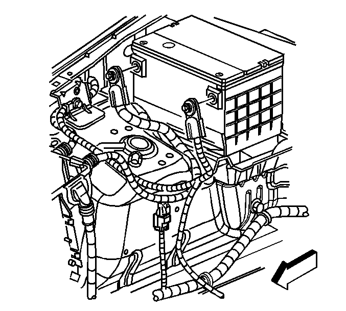
Position and secure the overflow hose to the vehicle.
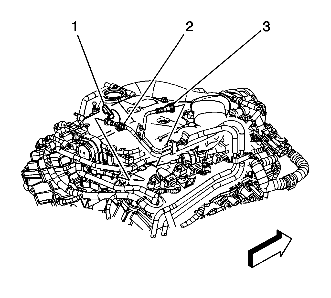
Important: Plug the fuel pipe and cap the fuel rail to prevent fuel loss and/or contamination.
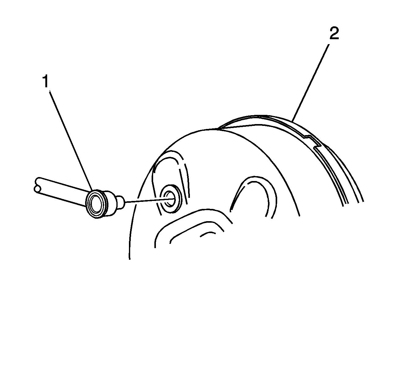
Position and secure the brake booster hose to the engine.
Position and secure the I/P harness to the vehicle.
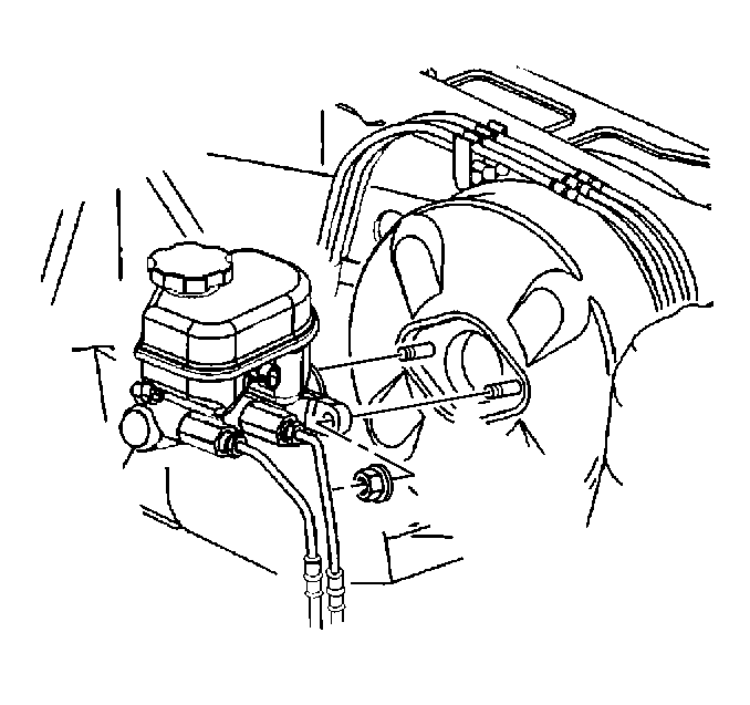
Important: Do NOT disconnect the brake pipes from the master cylinder.
Important: Cap and/or plug the brake pipes and the brake pressure modulator valve (BPMV) in order to minimize brake fluid loss.
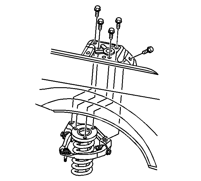
Important: Secure the shock modules to the lower control arms with a suitable strap in order to prevent damage to the front brake hoses.
Important: Ensure that all the hoses, wires, pipes and shock modules clear the vehicle during the removal process.
Installation Procedure
- Install the engine mount brackets with the engine mounts.
- Use a floor crane in order to install the engine to the frame.
- Install the ECM with the ECM bracket. Refer to Engine Control Module Replacement .
- Install the water outlet. Refer to Water Outlet Removal .
- Install the block heater. Refer to Coolant Heater Replacement .
- Install the flywheel. Refer to Engine Flywheel Installation .
- Install the intake manifold. Refer to Intake Manifold Installation .
- Install the crankshaft balancer. Refer to Crankshaft Balancer Installation .
- Install the right exhaust manifold. Refer to Exhaust Manifold Installation - Right Side .
- Install the oil filter adapter. Refer to Oil Filter Adapter Installation .
- Install the left exhaust manifold. Refer to Exhaust Manifold Installation - Left Side .
- Install the oil level indicator. Refer to Oil Level Indicator and Tube Installation .
- Install the generator and the generator bracket. Refer to Generator Installation .
- Install the power steering pump. Refer to Power Steering Pump Installation .
- Install the A/C compressor. Refer to Air Conditioning (A/C) Compressor Installation .
- Install the idler pulley. Refer to Drive Belt Idler Pulley Installation .
- Install the drive belt tensioner. Refer to Drive Belt Tensioner Installation and Drive Belt Installation .
- Install the drive belts. Refer to Drive Belt Removal .
- Install the transmission-to-engine and flywheel-to-torque convertor bolts. Refer to Transmission Replacement .
- Install the starter motor. Refer to Starter Motor Replacement .
- Remove the EN 46114 from the engine.
- Connect the radiator hoses to the water outlet housing and the coolant inlet pipe. Refer to Radiator Inlet Hose Replacement and Radiator Outlet Hose Replacement .
- Install the TOC pipes to the engine, radiator and the transmission. Refer to Automatic Transmission Oil Cooler Hose Replacement .
- Install the engine wiring harness and related components.
- Install the HO2S connectors.
- Install the thermostat housing with the heater pipes, heater hoses and surge tank outlet hose. Refer to Engine Coolant Thermostat Housing Replacement .
- Install the catalytic converters with the oxygen sensors. Refer to Catalytic Converter Replacement .
- Remove the cap or plug from the fuel line.
- Install the fuel lines to the fuel rail and the EVAP purge solenoid. Refer to Metal Collar Quick Connect Fitting Service .
- Install the purge line (3) to the purge solenoid.
- Connect the ECM electrical connector. Refer to Engine Control Module Replacement .
- With the aid of an assistant, raise the table and/or lift the vehicle to install the engine, transmission, front frame and front suspension assembly to the vehicle.
- Install the front frame bolts (2).
- Install the transmission support to underbody bolts. Refer to Transmission Brace Replacement .
- Remove the powertrain lift/support table.
- Install the right and left shock module upper mounting bolts. Refer to Strut Assembly Replacement .
- Connect the transmission shift linkage to the transmission. Refer to Range Selector Lever Cable Replacement .
- Install the intermediate steering shaft . Refer to Intermediate Steering Shaft Replacement .
- Install the front tire and wheel assemblies. Refer to Tire and Wheel Removal and Installation .
- Install the front brake pipes and retainers to the underbody.
- Connect the rear brake pipes (two center pipes) to the BPMV. Refer to Electronic Brake Control Module Replacement .
- Connect the radiator side air baffles to the radiator.
- Install the air deflector.
- Install the master cylinder.
- Connect the engine harness electrical connector at the frame.
- Install the ground wire and bolt to the frame.
- Connect the wiring harness to the TCM. Refer to Transmission Control Module Replacement .
- Connect the engine module wiring harness connectors.
- Connect and lock the I/P electrical connector.
- Connect the mass air flow sensor electrical connector.
- Connect the brake fluid level switch electrical connector from the master cylinder.
- Connect the brake booster vacuum hose (1) to the brake booster (2).
- Connect the purge line (3) to the purge solenoid.
- Connect the fuel pipe (2) to the fuel rail. Refer to Metal Collar Quick Connect Fitting Service .
- Connect the heater hoses to the heater core. Refer to Heater Inlet Hose Replacement and Heater Outlet Hose Replacement .
- Connect the overflow hose to the coolant overflow tank.
- Connect the air conditioning pressure switch electrical connector and the liquid line to the evaporator.
- Connect the air conditioning suction hose to the evaporator and install the suction hose bracket to the shock tower.
- Install the air cleaner duct. Refer to Air Cleaner Inlet Duct Replacement .
- Install the battery. Refer to Battery Replacement .
- Install the fuel injector sight shield. Refer to Fuel Injector Sight Shield Replacement .
- Connect the battery positive cable to the battery and the underhood electrical center. Refer to Battery Positive Cable Replacement .
- Connect the battery negative cable from the battery and the body. Refer to Battery Negative Cable Replacement .
- Remove the J 42640 from the steering column.
- Fill the cooling system. Refer to Cooling System Draining and Filling .
- Charge the air conditioning system. Refer to Refrigerant Recovery and Recharging .
- Bleed the brake system. Refer to Antilock Brake System Automated Bleed Procedure .
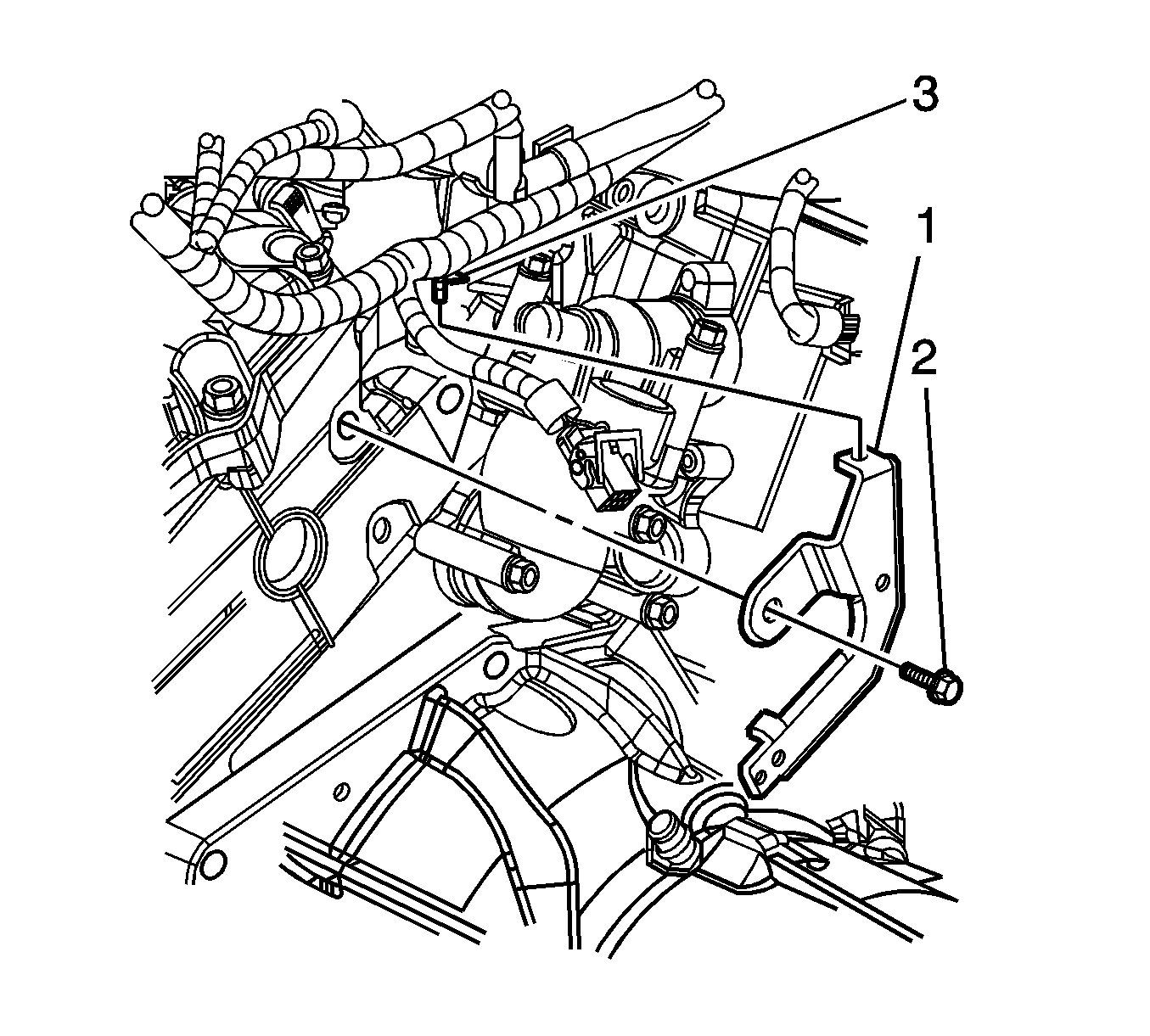

Important: Ensure that all the hoses, wires, pipes and shock modules clear the vehicle during the installation process.
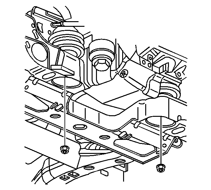


Notice: Refer to Fastener Notice in the Preface section.
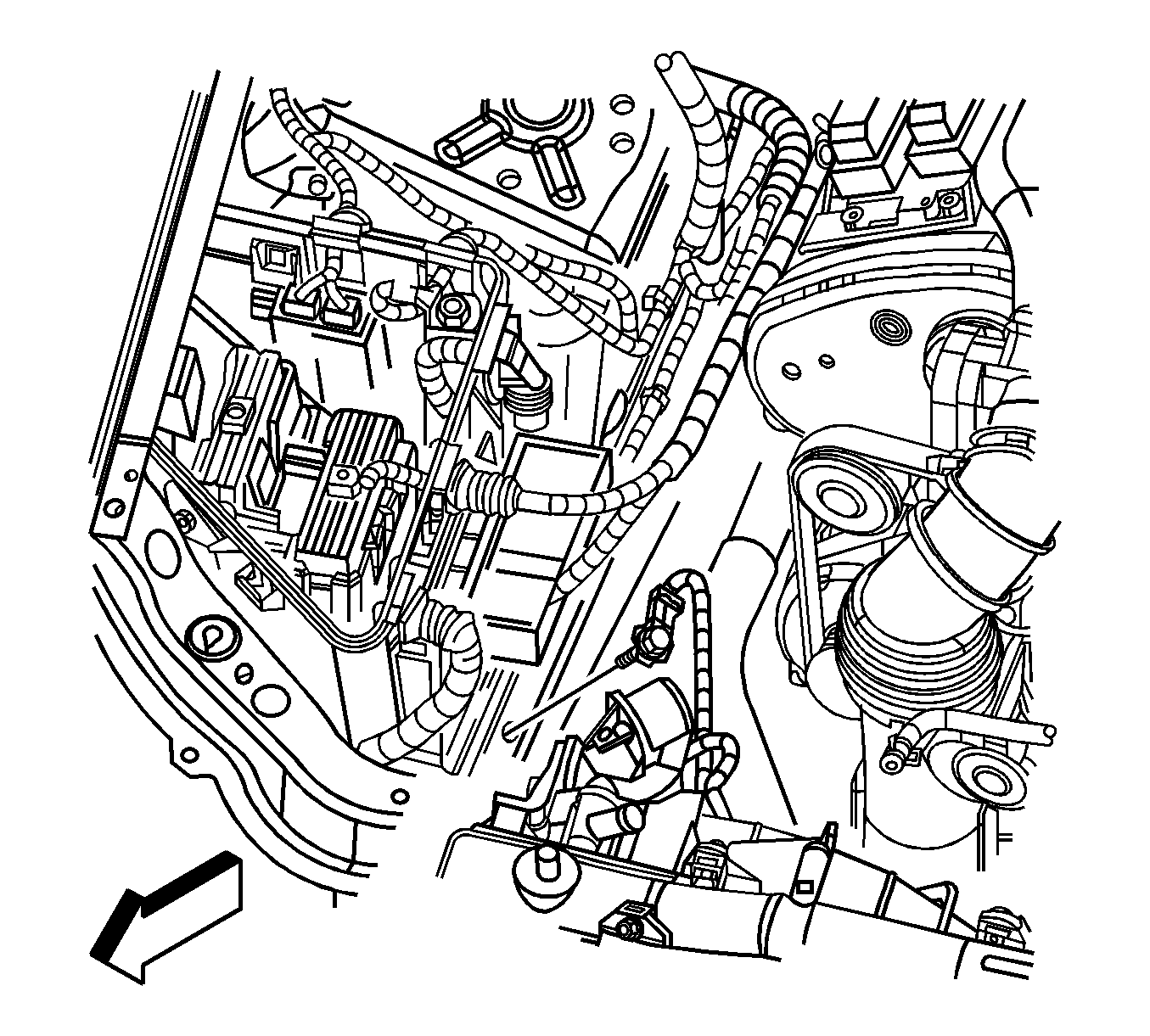
Tighten
Tighten the engine harness ground wire to longitudinal rail bolt to 10 N·m (89 lb in).


