PULSE WIDTH MODULATED EGR CHART REVISION

Models Affected: 1984 2.8L (VIN CODE X & Z) AND 5.0L (VIN CODE Y) ENGINES
NOTE: THIS BULLETIN SUPERSEDES 84-6E-20 DUE TO RECENT CHANGES IN CHART C-7A. PLEASE DISCARD 84-6E-20 AND REPLACE WITH BULLETIN 84-6E-20A
The charts contained in this bulletin should be used in place of C-7A currently in the 1984 Chassis Service Manual. Chart C-7C is an additional chart and should be used when necessary until it is issued with the next Chassis Service Manual revision.
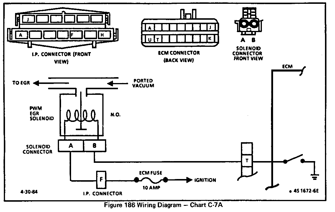
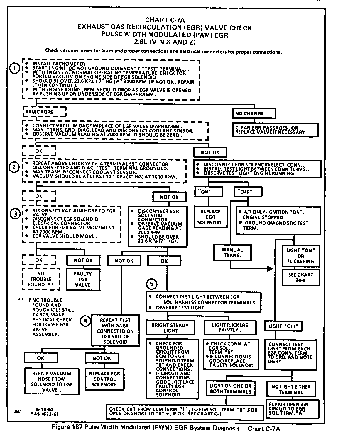
CHART C-7A, PULSE WIDTH MODULATED (PWM) EGR
PWM EGR is an ECM control that pulses the vacuum signal to the EGR. This is accomplished through a normally open EGR solenoid which when energized by the ECM shuts off the vacuum to the EGR valve diaphragm. This system can pulse the solenoid many times per second (PWM). The EGR solenoid is always energized (EGR off) when any one of the following conditions are met:
Park/ Neutral switch closed (selector in park or neutral) Throttle Position greater than specified. Coolant temperature less than specified.
1. Checks to see if the EGR passages are restricted or if the valve is stuck open.
2. With the 4 wire EST connector disconnected, the ECM thinks the engine is not running. Grounding the test terminal, under this condition, causes the ECM to pulse the EGR solenoid "ON" and "OFF" for testing which will result in a controlled vacuum supply to the EGR valve diaphragm at 2000 RPM.
3. By disconnecting EGR solenoid electrical connector, control by the ECM is overridden and the normally opened EGR solenoid will pass available vacuum. At 2000 RPM EGR valve should move if EGR control system is functioning properly.
4. If vacuum is below 23.6 KPa (7" HG) at 2000 RPM with EGR solenoid electrical connector disconnected, a leak or restriction between test point ( EGR diaphragm ) and source is evident.
5. Checks EGR solenoid electrical control circuit. The test light should "flicker faintly" if the ECM, harness and connections are OK. "Flicker faintly" refers to a slightly pulsing glow as opposed to a "bright steady" glow from a continuous ground path.
Steps 1,2 and 3 represent an EGR system operation check.
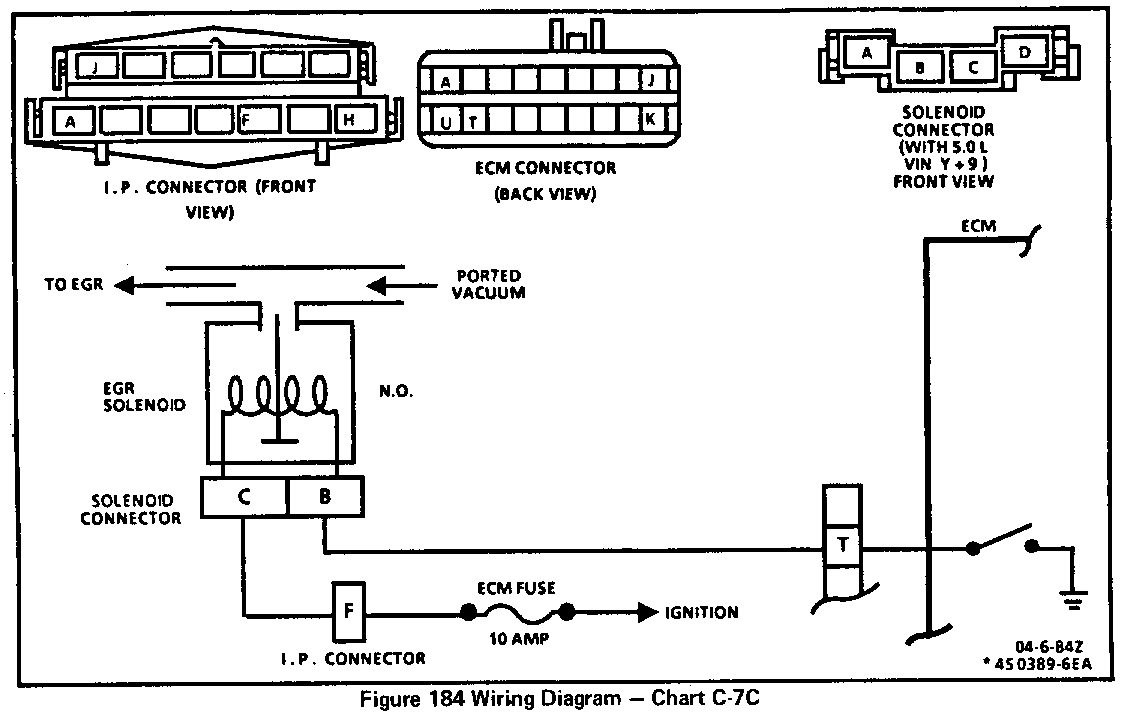
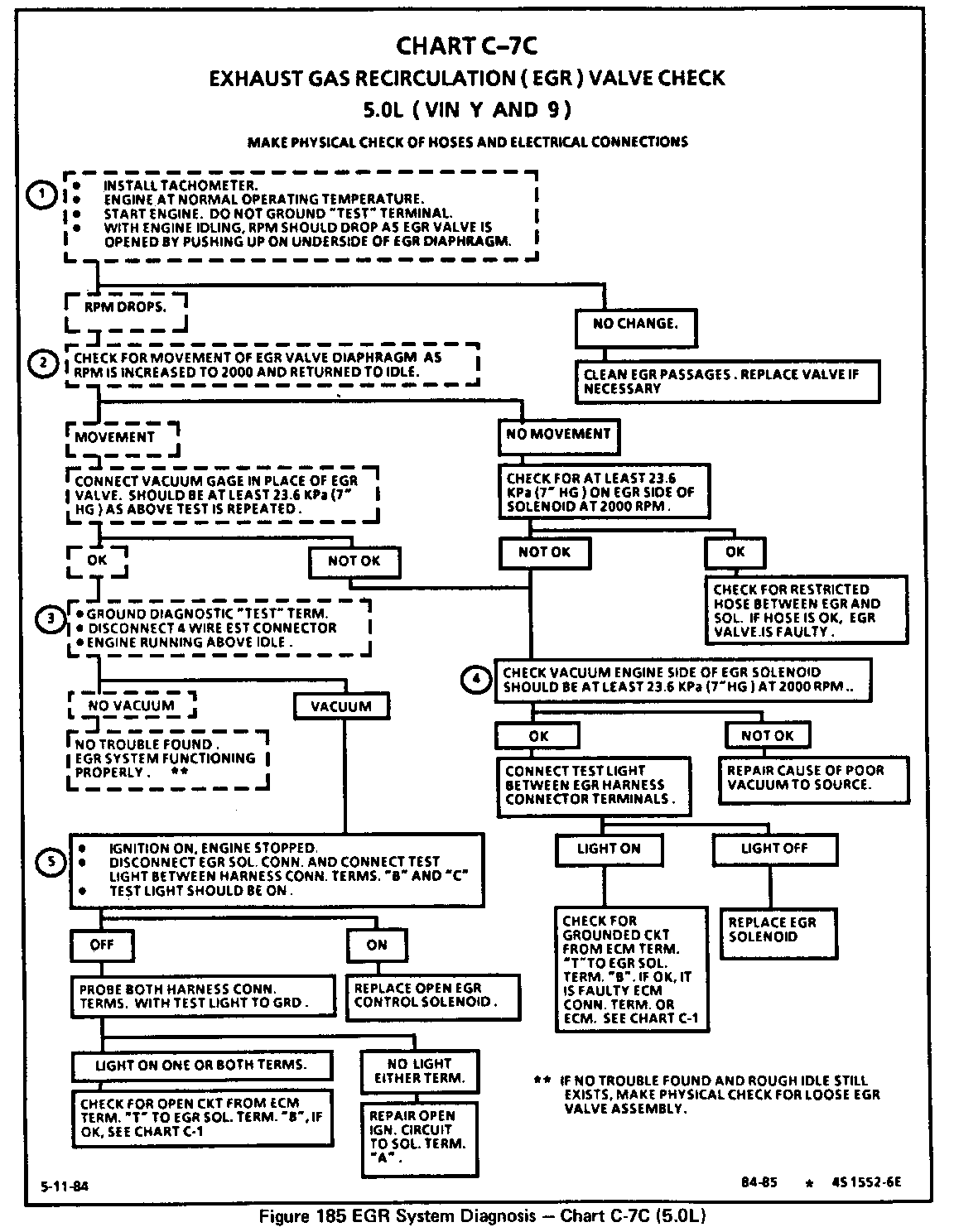
CHART C-7C, EXHAUST GAS RECIRCULATION 5.0L (VIN Y) ONLY
The Exhaust Gas Recirculation (EGR) valve is controlled by a normally open solenoid (allows vauum to pass when de-energized.)
When the ECM energizes the solenoid, by completing a ground circuit, the EGR is turned "OFF". The ECM controls EGR based on the following inputs:
Coolant Temperature Throttle Position Engine RPM TCC State Barometric Pressure
1. This tests for restricted valve or passage in manifold. Engine should run roughly or stall as valve is opened manually
2. EGR valve diaphragm should begin to move as the engine speed approaches 2000 RPM.
3. This step should result in the EGR solenoid being energized, shutting off vacuum to the EGR valve diaphragm. This indicates EGR system is functioning properly.
4. Vacuum below 23.6 KPa (7 ".HG ) at 2000 RPM is insufficient for proper EGR operation. Lower vacuum readings require repair.
5. Disconnecting the four wire EST connector with diagnostic terminal grounded causes ECM to ground CKT from ECM terminal "T" to EGR solenoid terminal "B". The light should be on. (EGR vacuum off.)
Steps 1,2 and 3 represent an EGR system operation check.


General Motors bulletins are intended for use by professional technicians, not a "do-it-yourselfer". They are written to inform those technicians of conditions that may occur on some vehicles, or to provide information that could assist in the proper service of a vehicle. Properly trained technicians have the equipment, tools, safety instructions and know-how to do a job properly and safely. If a condition is described, do not assume that the bulletin applies to your vehicle, or that your vehicle will have that condition. See a General Motors dealer servicing your brand of General Motors vehicle for information on whether your vehicle may benefit from the information.
