AIR NOISE/ WIND NOISE DIAGNOSE AND REPAIR

1985-89 C/H CARS
*This bulletin is being revised to add 1989 models and include a Cadillac specific bulletin at the end of this bulletin.
In the event of a customer concern regarding an objectionable air/windnoise, this bulletin has been formulated to serve as a guide. Some areas and illustrations are of a general nature and are meant to provide background information TABLE OF CONTENTS ----------------- GENERAL INFORMATION ------------------- A. Beginning the Repair B. Responsibility of The Service Advisor
THE WINDNOISE CONDITION
A. Questions Specific To All Windnoise Conditions
B. Analyzing The Windnoise
1. Door Alignment 2. Outside Sports Mirrors 3. Areas and Percentages of Reported Objectionable Windnoise 4. Classifications of Windnoise
THE ROAD TEST
DIAGNOSIS TECHNIQUES
1. Compressed Air and Soapy Water Test 2. Dollar Bill Test 3. Flashlight or Shop Light Test 4. Sonic Tester and Tone Generator 5. Visual Inspection 6. Tracing Powder or chalk Test 7. Air Pressure Test 8. Soap Suds or Bubble Test 9. External windnoise
SEALERS AND RELATED PRODUCT USAGE
A. Adjustments and Sealing Repair Operations B. Stationary Glass Repairs C. Vinyl Reveal Moulding
SPECIFIC AREAS
A. Windshield B. Front Door C. Rear Door D. Back Glass
GENERAL INFORMATION
Beginning the Repair
A. The repair process actually begins: when the customer brings the vehicle to the dealership or repair shop and the condition is written up on a repair order.
A lot of valuable information can be obtained by the service advisor during his/her initial contact with the customer if questions regarding the vehicles condition are channeled in the right direction.
B. Responsibility of the Service Advisor
As the liaison between the customer and the repairman, the service advisor obtains all needed information and writes it in a common service language to assist everyone in the repair cycle in making a lasting leak repair in an efficient manner the first time.
The service advisor should keep in mind that the cause of a windnoise can vary between body styles and from vehicle to vehicle within a given body style.
It is also possible that a reported condition on a given vehicle may never be encountered again on any other vehicle.
Cover the three "W's" with the customer concerning the vehicle. They are as follows:
1. WHAT? Windnoise. 2. WHERE? Specific area(s) leak(s) are located. 3. WHEN? Under what condition(s) does the leak/noise occur?
THE WINDNOISE CONDITION
The first step of the repair process in correcting a windnoise condition is to identify the cause(s) of the noise.
Gain a thorough understanding of the circumstances under which the noise was created. A determination must be made as to whether the cause of the noise is air escaping from the vehicle or outside air turbulence.
A. Questions Specific To All Windnoise Conditions
To assist in diagnosing and repairing the owner's vehicle quickly, the following information should be obtained:
1. What specific noise is objectionable?
a. Whistle? b. Flutter? c. Rush of Air?
2. Under what condition does the noise occur?
a. In motion? b. Heater/AC blower motor on or off?
3. Does the noise appear to be.
a. Air leaving the body? b. Air passing over the body's exterior surface?
4. In which occupant seating position of the vehicle is the noise most objectionable?
a. Front Seat b. Rear Seat
1. Driver's seat? 1. Left passenger's seat? 2. Centre passenger's seat? 2. Centre passenger's seat? 3. Right passenger's seat 3. Right passenger's seat?
5. At what speed does the specific noise first occur?
a. Less than 10 miles per hour? b. 10-34 miles per hour? c. 35-55 miles per hour? d. Over 55 miles per hour?
6. In what general area does the noise appear to originate?
a. Front of Vehicle b. Sides of Vehicle
1. Grille 1. Windshield Pillar 2. Bumper 2. Upper 3. Hood 3. Centre 4. Fender 4. Lower 5. Shroud (Cowl) area 6. Windshield
c. Rear of Vehicle
1. Rear Window 2. Tulip Panel 3. Tailgate/Window (Wagons) 4. Quarters 5. Rear Bumper 6. Roof Rack (Wagons)
B. Analyzing Windnoise
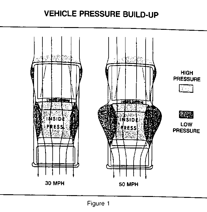
When a vehicle is in motion, it strikes the air causing it to bend around the vehicle and deflect around the windshield pillars (Figure 3-1). When this occurs, areas of high and low pressure are then created. It is the difference between the pressure build up that varies levels of sound pitches. As air strikes the base of the windshield, it backs up. This causes a low pressure centre to develop outside the vehicle around the front pillars and side windows.
The amount of low pressure build-up along the sides of the vehicle is increased by the impact speed of the air asit strikes against the windshield surface. The faster the vehicle is traveling, the greater the pressure difference becomes.
This pressure build-up at the windshield causes the air flow that is filtered through the vehicle vents and/or air conditioner to build up high pressure inside of the passenger compartment. The faster the vehicle is traveling, the greater the inside pressure becomes. The speed of the vent fan will also have an effect on pressurization of the passenger compartment.
The pressure pushes outward on the glass and other seals. This situation is not normally a problem, but if a door or window is out of alignment, leaks can develop and cause a wind whistle.
The high inside pressure and low outside pressure is separated only by vehicle's sheet metal panels, glass, weatherstrips and body seals.
When an opening is created at a joint at any of these areas, the high inside air pressure will move toward the low outside pressure area to create an air leak.
The shape of the opening would then determine if an audible noise or whistle can be heard. It may require a specific vehicle to create enough high pressure to break the seal.
The vehicle has a large area, plus a number of exterior attachments in which air must move around. As a result, some rush of air will be heard and is considered normal.
Examples are:
1. Door Alignment-A door should fit properly into the Vehicles body opening for several reasons:
a. Appearance b. Ease of operation c. Smooth quiet air flow.
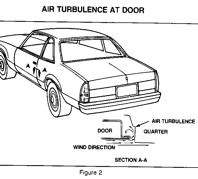
A vehicle door that is not properly aligned will act similar to an air scoop. The inside area of the door jamb will become pressurized and create air turbulence which may be transmitted as noise inside of the passengers compartment (Figure 2).
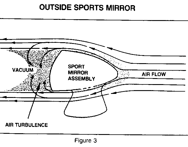
2. Outside Sports Mirrors-They are shaped similar to a bullet in front, and flat across the face or rear.
When a vehicle is moving, its outside mirrors strike and bend the air around it. This flow of air around the body of the mirror can create a low pressure area or vacuum across its face allowing turbulence to build up (Figure 3).
Because of the styling design of the sports mirror, the noise cannot be eliminated.
The noise source can be verified by taping over the face of the mirror and then subject vehicle to the same road conditions.
The high pressure inside air moves toward the low pressure (vacuum) area through the door belt sealing strips and/or any other voids in the mirror head or inside the door. If the air passage is shaped just right, an objectionable air noise can be heard. Thus, you could have a wind whistle and wind roar condition.
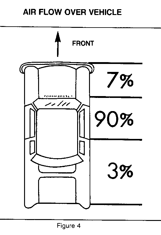
3. Areas and Percentages of Reported Objectionable Windnoise (Figure 4).
It is estimated that 7% of all reported objectionable windnoise conditions can be located at the front end (bumpers, grille, hood and fenders) of the vehicle.
Another 90% of the reported objectionable windnoise conditions are located in the area between the dash panel and the rear edge of the door or centre pillar.
The remaining 3% of those reported conditions were located between the rear edge of the door or centre pillar area to the rear of the vehicle (usually vent window seals, luggage racks or tailgates and wind deflectors).
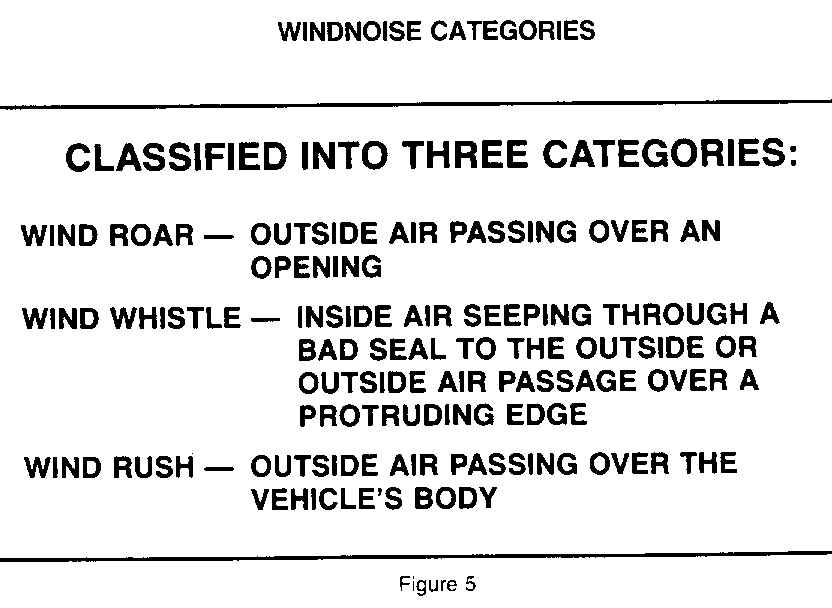
4. Classifications of Windnoise-It is important to note that wind will not create a noise until it is forced to change directions or is forced to move around an object.
Windnoise Categories, (Figure 5) may be classified into the following:
WINDNOISE CATEGORIES
THE ROAD TEST
To analyze a reported windnoise condition, a test drive in the vehicle is necessary due to the many variables that could singularly or collectively be attributed to creating the objectionable windnoise condition.
NOTICE: OFTEN THERE IS ONE PRIMARY LEAK SOURCE AND ONE OR MORE SECONDARY LEAKS THAT CONTRIBUTE TO THE NOISE CONDITION.
REPAIRING ONLY ONE OF THE CONTRIBUTING LEAK SOURCES MAY NOT COMPLETELY REPAIR THE TOTAL CONDITION, BUT ONLY REDUCE IT.
FOR SAFETY REASONS: An assistant should drive the vehicle while the technician checks for the location of the reported condition(s). In addition, the following items should be taken for utilization by the technician during the test drive to aid in pinpointing and marking area(s) of the leak:
1. Mechanics Stethoscope or Vacuum Hose. 2. Masking Tape (2" in width). 3. Strip Caulk. 4. China Marking Pencil. 5. Screwdriver.
A regular route for the road test should already have been chosen. The road test should include smooth and straight streets that run in all four directions, (North, South, East and West). It should be an area where there is little traffic or noise that would interfere with the test.
The vehicle should be driven at the speed in which the noise was noticed by the customer or until it is heard. Safe legal speeds should never be exceeded.
First determine if the noise is an objectionable windnoise as opposed to normal or standard sounds.
If noise can be heard with the door glass lowered and vehicle is being driven, it is EXTERNAL WINDNOISE.
Locating an EXTERNAL WINDNOISE condition can be accomplished by taping various mouldings and gaps until the noise is eliminated to pinpoint the exact cause of the noise.
If noise cannot be heard with the windows lowered, this indicates a body seam is leaking or a sealing surface such as a glass to weatherstrip or door weatherstrip to door is poor. INTERNAL WINDNOISE is air leaving the body.
The first step in locating the source of INTERNAL WINDNOISE is to tape off the body lock pillar pressure relief valves. This will cause air pressure to build-up inside the vehicle and enhance the windnoise. Trace the suspected seal using the stethoscope or section of vacuum hose to locate the leak area.
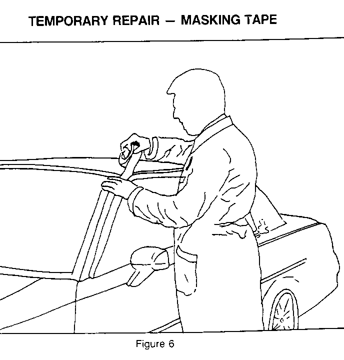
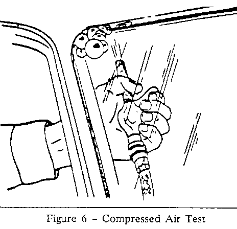
Temporarily repair the condition with masking tape (Figure 6). Adjust tape as required. Continue testing to determine if noise has been eliminated or other leak areas exist.
When all reported leak conditions have been located, return to shop and make permanent repairs utilizing proper alignment techniques and sealing materials as required.
DIAGNOSIS TECHNIQUES
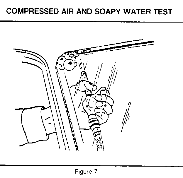
1. Compressed Air and Soapy Water Test
Another form of localized testing is performed utilizing compressed air and a soapy water solution.
Using a mixture of liquid soap and water, or a foaming type glass cleaner, apply it directly to the exterior surface of the suspected leak area.
Apply compressed air (30 p.s.i.-205 kPa) to the suspected area from inside of the vehicle outward at the panel joint, or suspected seam or seal (Figure 7).
Large bubbles will appear outside as the exact leak point is reached.
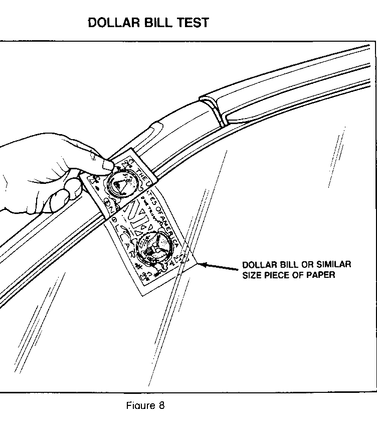
2. Dollar Bill Test
Place a dollar bill or similar size piece of paper between weatherstrip and contact surface, then close door, lid, etc. (Figure 8).
Slowly withdraw the bill or paper after panel is closed, to check the amount of pressure on the weatherstrip.
There should be a medium amount of resistance as the bill or paper is slowly withdrawn. Continue around the entire seal area. If there is little or no resistance, it indicates there is insufficient contact to form a good seal. This test may indicate that the door, glass, or weatherstrip is out of alignment.
3. Flashlight or Shop Light Test
A bright light may be used to check panel seams and openings. Have a helper move light along suspected seam such as the rear wheelhouse, and check for light leaks inside the trunk.
4. Sonic Tester and Tone Generator
The sonic tester and tone generator (J-23455.01) is a useful tool available for testing seams, seals and weatherstrips.
The sonic tester consists of a microphone pickup that is monitored through a headset and a tone generator (transmitter) that is placed inside the vehicle or in the trunk. Pass the pickup head along each seam or weatherstrip until a noise is detected.
5. Visual Inspection
The source of the condition is not always in the same location where the noise is heard. The visual inspection should begin and centre around the suspected area(s).
INSPECT VEHICLE FOR:
a. Misaligned Components b. Loose Fasteners c. Torn Weatherstrips d. Broken Weld Joints e. Sealer and/or Adhesive Skips
6. Tracing Powder or Chalk Test
Best suited for checking weatherstrip contact of doors, rear compartment lids, door glass, sunroof, vista vents, hatch roof and tailgate areas. Tracing powder is conveniently available in aerosol cans.
Spray powder or apply soft chalk to the weatherstrip contact surface and close the door, hatch, lid, etc.; do not slam. Check the weatherstrip mating surface for unbroken areas of powder or chalk.
Areas that have a 1/8 inch or 3.17mm skip in the powder or chalk line should be considered leak areas.
Close the panel completely, without slamming, to press weatherstrip firmly against its mating surface, and then, reopen.
The applied line on the weatherstrip wil be marred where there is good contact. There will be a corresponding imprint left wherever the weatherstrip touched its mating surface.
Any gaps or irregularities in the powder or chalk line on either surface indicates a poor seal.
7. Air Pressure Test
Windnoises are often caused by high pressure air escaping whenever the vehicle travels at road speed. However, this condition can often be recreated without the vehicle moving by performing the following static test.
To recreate this effect, proceed as follows:
a. Completely mask off both pressure relief valves.
b. Turn on the vehicle's vehtilation fan, roll up all windows and close all openings (doors, sunroof, etc.). This will cause an abnormal amount of high pressure to build up inside of the vehicle. The buildup of air pressure will travel through any voids or poor seals.
c. With a stethoscope or a length of heater hose, listen for escaping air from the outside of vehicle along the door and window seals.
A SMOKE OR DUSTING POWDER TEST can be used in the same manner as the above test procedure, except instead of listening for for the air leak area(s), the exact location can be seen as the smoke or powder travels thrbugh the void or bad seal. Dusting powder often leaves a tell-tail path in the void area.
Soap Suds or Bubble Test
This test can be performed using two different methods
The FIRST METHOD is similar to the Smoke or Dusting Powder Test:
a. The interior of the vehicle is pressurized and a soapy solution or a foamy glass cleaner is applied to potential leak areas on the outside of the vehicle.
b. Bubbles will appear at the void or leak point as the air escapes, pinpointing the exact area.
A SECOND METHOD of detecting the leak is the following:
a. Apply the soapy solution or foam glass cleaner to the suspected leak area (windshield area, body joint, taillight, etc.).
b. Apply air pressure with an air hose from inside of the vehicle at the suspected leak area. Do not exceed 205 kPa (30 psi).
c. Bubbles will appear at the voids, thereby pinpointing the leak area.
This SECOND METHOD is generally used for water leak diagnosis but can also apply to some windnoise diagnosis testing procedures.
External Windnoise
Visually inspect vehicle in suspected leak area(s) for loose trim, loose fasteners, and poorly aligned panels or components. Grilles may whistle under certain conditions.
PERFORM THE FOLLOWING TO DIAGNOSE AN EXTERNAL WINDNOISE:
a. Road test the vehicle to determine if the noise is coming from the front of the vehicle.
b. If the noise is coming from the front end, mask off the entire grille, headlight bezel areas and windshield upper reveal moulding. Care must be taken not to allow masking to restrict air flow and vehicle overheating.
c. Retest the vehicle if the noise can no longer be heard.
d. Remove a small section of the masking tape and retest for the noise.
e. Continue this procedure as required until the noise has been located.
f. Take vehicle back to shop and make permanent repairs.
SEALERS AND RELATED PRODUCT USAGE
Before attempting to seal any leak, it is important to know the various types of sealers that are recommended to repair those areas of the vehicle where leaks may be encountered.
A. Stationary Glass ---------------- NOTICE: URETHANE SEALANT (CANSPO #993110) IS THE ONLY GM RECOMMENDED SEALANT FOR:
1. WINDSHIELD TO BODY OPENINGS. 2. BACK GLASS TO BODY OPENINGS.
B. Quarter Windows --------------- Generally sealed with one or more of the following:
1. Urethane Sealant, Applied Fasteners, Butyl Tape, Window Weld (Flow Grade) Sealant or Resealant Wet-Dry.
C. Metal Joints and Seams ---------------------- 1. Paintable body sealers such as: Heavy Drip Check Sealer, Drip Check Sealer, Leak Sto pSealer, Wet/Dry Leak Check Sealers, etc.
D. Small Pin Holes in Wheelhouse Seams ----------------------------------- 1. Brushable Seam Sealers. 2. Body Schutz or Rubber Guard. 3. Rubberize Undercoating.
E. Weatherstrip Retainers ---------------------- 1. 3M #6375 Scotchfoam Black Vinyl Foam Tape 2. Kent #40519 High Strength Tape 3. Medium Body Sealer, (Bedding and Glazing Compound)
F. Screws, Nuts, Rocker Sill Plates, Quarter Extensions, Tail Lamp and Quarter Lamp Housings, Gaskets and Scalp Mouldings.
Any of the above areas can be successfully sealed with a thumb grade type sealer.
Some thumb grade sealers are:
1. Bulk-Caulk. 2. Strip-Caulk, (Dum-Dum). 3. Seal 'N' Caulk.
G. Heater/AC Module to Dash Seam ----------------------------- 1. Medium Body Sealer, (Bedding and Glazing Compound).
H. Weatherstrips ------------- Adhesive retainer weatherstrips can be sealed with:
1. CANSPO #12345097 - Black Weatherstrip Adhesive. 2. 3M #8011 - Black Weatherstrip Adhesive. 3. Kent #10180 - Stick-It Black Weatherstrip Adhesive.
I. Release Agent ------------- A special solvent blend that quickly softens adhesive bonds between the weatherstrip and metal to aid in weatherstrip removal or replacement.
1. Kent #30125 - Special Release Agent SR-A. 2. 3M #08971 - Release Agent. 3. American Sure Seal #SRI - Release It.
J. Tracing Powder -------------- Use for checking weatherstrip contact to a mating surface.
1. Kent #20065 - Tracing Powder. 2. American Sure Seal #STP - Tracing Powder.
K. Adhesive Cleaner ---------------- A special blended solvent that will not harm the paint finish., vinyl or fabric.
1. Kent #60070 - Acrysol Body Solvent. 2. American Sure Seal #BSS General Purpose Cleaner. 3. 3M #08984 - General Purpose Adhesive Cleaner.
L. Silicone Paste -------------- A paste material. When applied on the weatherstrip surface, it deposits a thin protective film coating over the outer surface.
1. CANSPO #992887 - Silicone Paste. 2. Kent #50015 - K-44 Silicone Lube. 3. American Sure Seal #LlOOO - Silicone Tube Grade Compound.
A. ADJUSTMENTS AND SEALING REPAIR OPERATIONS
Proper sealing prevents wind and water from entering where it's not wanted. It also prevents corrosion and electrical malfunctions. The automobile body itself is designed to channel water down and out to prevent it from accumulating or causing damage.
The procedures for water leak and windnoise repairs are similar. The actual procedure used depends primarly on the type of seal being repaired, rather than on the nature of the condition.
Leaks around the door opening weatherstrip do not always indicate a faulty weatherstrip. At times, a door or a door glass adjustment will take care of the leak condition.
To determine if the door and/or door glass requires adjustment, perform the following:
1. Set the door lock in its first catch, then check the effort needed to close door by standing with feet together about 24 inches (600mm) away from the body.
2. If right handed, place flat part of left hand on the panel near the door handle and push door closed. If left handed, place flat part of right hand on the panel near door handle and push door closed.
3. The door should close completely. If it does not...lower door glass and retest again to see if the glass was causing condition.
4. If the hard closing condition is still evident, continue to test by removing the door lock striker, and then slowly move door in toward the closed position. In the closed position, the rear vertical edge of the door should be parallel to the front vertical edge of the quarter panel.
5. A 3/4" (19.02mm) vertical gap between rear edge of door and front edge of quarter panel indicates that there is sufficient compression on the door weatherstrip.
6. If not parallel, and the vertical gap is larger at the bottom of the door, there may not be sufficient compression on the weatherstrip.
7. If this is the case, door hinges must be moved in or out until an even 3/4" (19.02mm) gap is set along the rear vertical edge of door.
8. Reinstall door lock striker. Roll door glass and test door again.
9. If door now closes properly, recheck leak condition to make sure that it has been corrected. If condition is still evident, it will be necessary to realign door glass.
B. Stationary Glass Repairs ------------------------ Water leaks in stationary glass installed with urethane sealant can be corrected without removing and reinstalling glass.
The following method applies if the urethane sealant materials furnished in CANSPO Kit No. 993110 is utilized.
1. Remove reveal moulding and any garnish mouldings in area of leak(s).
2. Use one of the previously described methods to locate leak(s).
3. Mark location of leak(s) and from outside the body, clean the area with water; then dry area(s) with air hose.
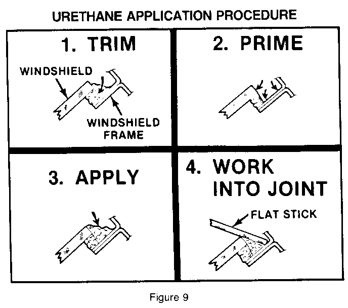
4. Using a sharp knife, trim off exposed edge of adhesive 3"-4" to either side of the leak, and prime the area. Use black primer supplied in kit (No. 993110), and follow labeled instructions for use (Figure 9).
5. Apply urethane sealant to area and 75mm (3") to 100mm (4") beyond each side of leak. Immediately work sealant into the joint with a flat stick to ensure a water tight seal along entire length of material application.
6. Test the new seal(s) using a LIGHT warm or hot water spray. DO NOT direct a heavy stream of water on freshly applied urethane sealant material.
7. Reinstall reveal and garnish mouldings.
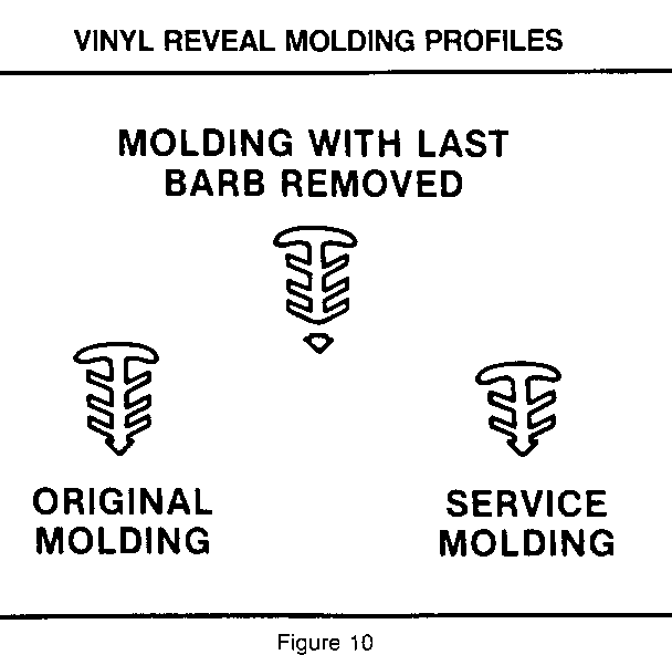
NOTICE: IF ORIGINAL MOULDINGS CANNOT BE REUSED (DUE TO DAMAGE, CUT SHORT, ETC.), DISCARD MOULDING AND REPLACE WITH A SERVICE MOULDING. THE SERVICE MOULDING HAS A SHORTER SHANK AND WILL NOT BOTTOM OUT WHEN INSTALLED.
C. Vinyl Reveal Moulding ---------------------- If original reveal moulding is vinyl, it can be reused by performing the following:
1. Trim off lower barb of moulding using a razor, knife, or scissors. Prefit in cavity.
2. Apply clear primer from urethane kit (Part No. 993110 or equivalent) to lower surface of moulding prior to reinstallation.
3. Apply urethane in cavity between body and glass.
4. Using a container filled with lukewarm water, flood the cavity filled with urethane. Moisture is the catalyst for the sealant and will speed up the cure of the material.
5. Start from the centre using hand pressure, press moulding into original location. Then apply additional water on top of moulding. If needed, apply tape over moulding to keep moulding flush to glass while curing.
6. Vinyl Reveal mouldings (Figure 10).
SPECIFIC AREAS
A. WINDSHIELD ----------- 1. Windshield header probable cause:
a. Skip in urethane sealant
Correction: Apply sealer to missed location (See Figure 9).
b. Moulding resonance
Correction:
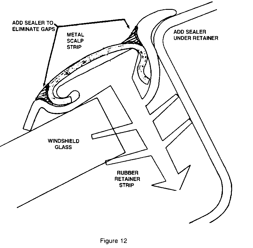
- Apply sealer between black plastic lip and roof (See Figure 12).
- Apply sealer between brite scalp and black plastic at leading and trailing edge. Smooth flush (See Figure 12).
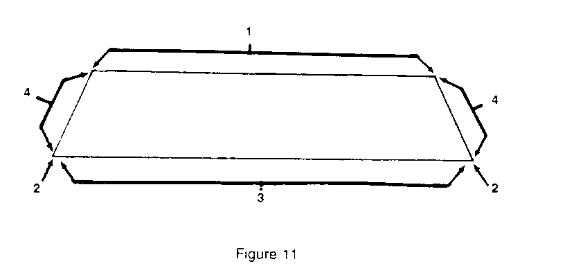
Areas 2-3-4 of Figure 11, probable cause:
a. Skip in urethane
Correction. Apply sealer to missed location (See Figure 9).
B. Front Door - Specific Areas
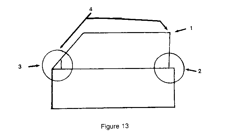
1. Upper rear corner, Area 1 of Figure 13:
a. Door Alignment-Door frame outboard of specification.
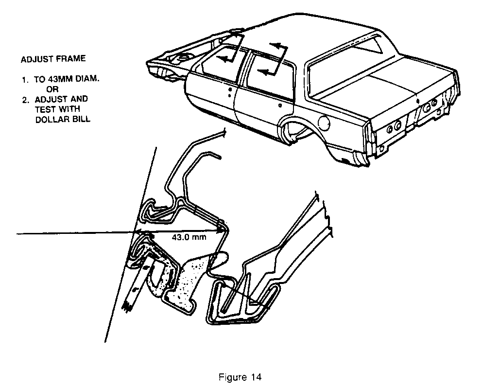
Correction: Adjust door frame inboard (See Figure 13).
b. Exposed Pinguide (Glass rear guide)
Correction: Readjust glass-See 1987 Body Service Manual Doors-"C,H" styles 5C-27.
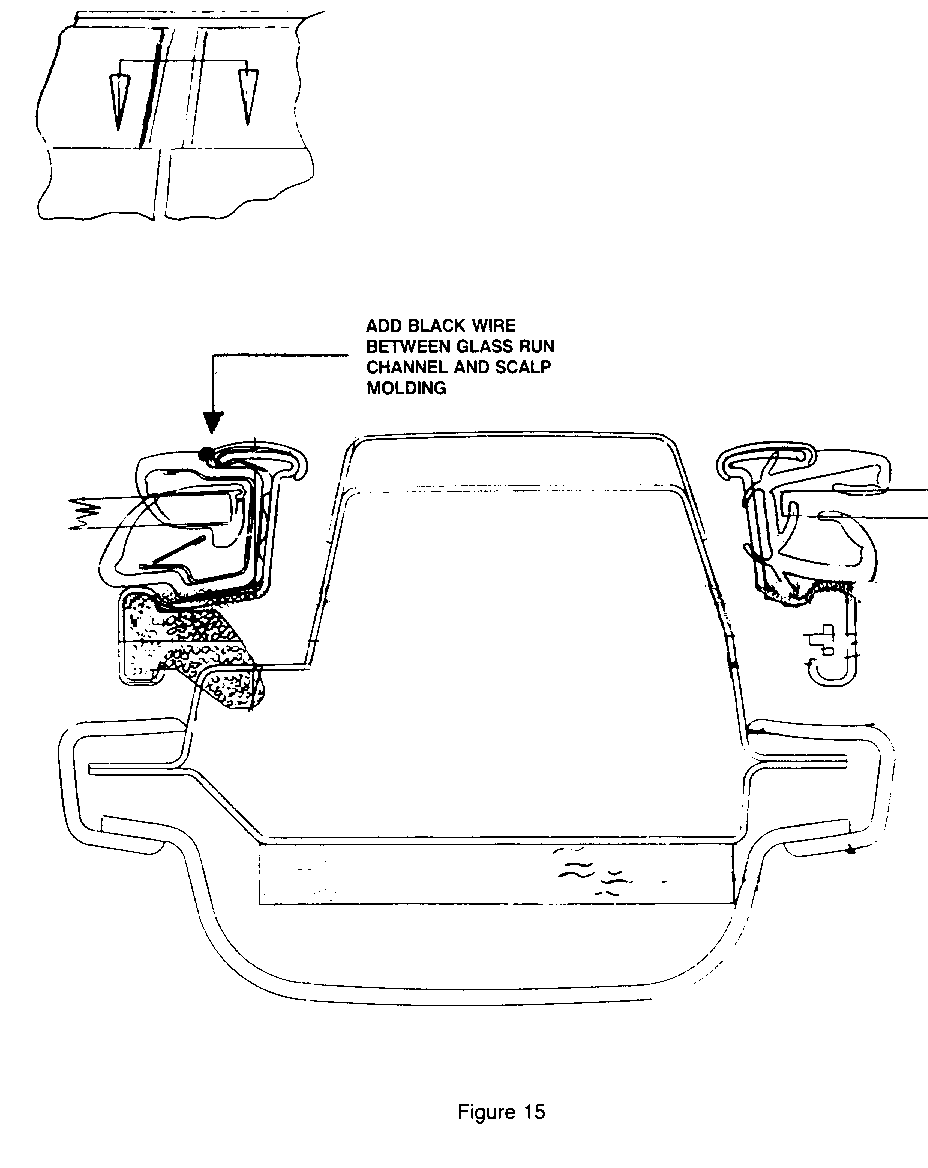
c. Insufficient compression of glass to glass run channel at rear vertical.
Correction: Add black vinyl coated electrical wire (approximately 5/64"-2mm outside dimension, length as required) between glass run channel and scalp moulding (See Figure 15).
2. Beltline at rear probable cause: Area 2 of Figure 13.
a. Missing seal at glass run channel to door frame at rear vertical.
Correction: Add 100mm x 19mm strip of Nitrile Tape to back of glass run channel, or replace glass run channel with 1988 part.
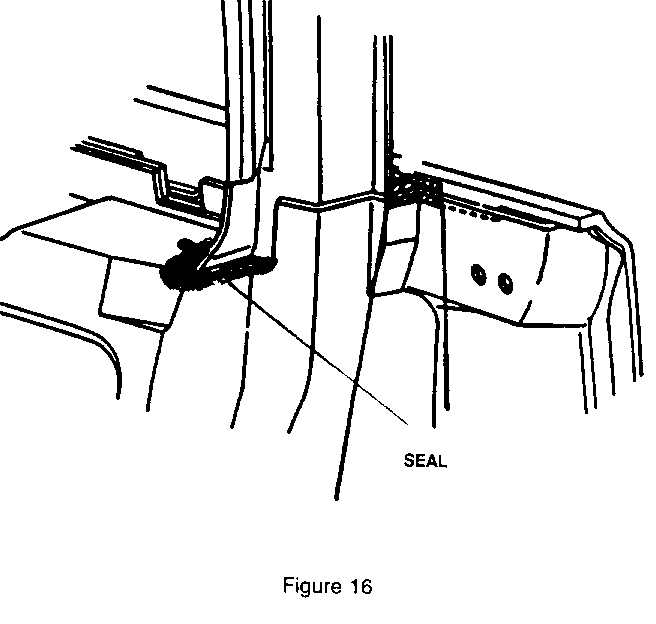
b. Misapplied thumb grade sealer caulking.
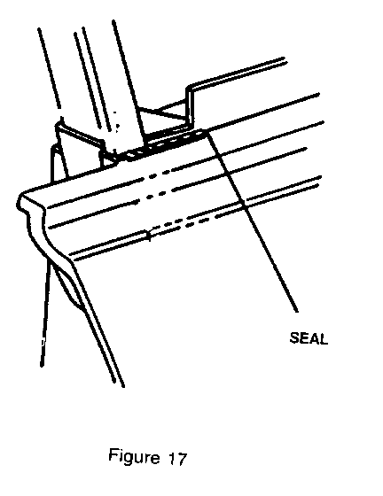
Correction: Apply as indicated (See Figures 15-17).
c. Out of Date Mucket Parts (Inner Rear Filler Beltline was a separate part, not part of glass run channel 1985-87.
Correction: Replace with 1988 integral muckets.
Part No. 20699064 - Right Sedan 20699065 - Left Sedan 20699066 - Right Coupe 20699067 - Left Coupe
d. Wrinkled door weatherstrip between beltline and first retaining nail
3. Mirror patch probable cause:
a. Missing or misinstalled auxiliary seals
Correction: Replace or reinstall seals
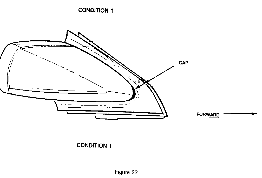
b. Misapplied thumb grade sealer
Correction: Apply as indicated (See Figures 17 and 22)
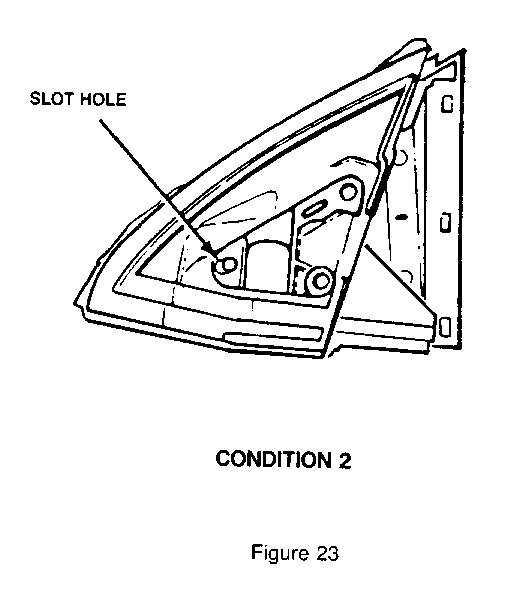
c. Gap at noise of mirror-1987 LeSabre, right side only (See Figure 23)
Correction:
1. Remove mirror. 2. Elongate front mirror attaching hole forward 2.Omm (See Figure 23).
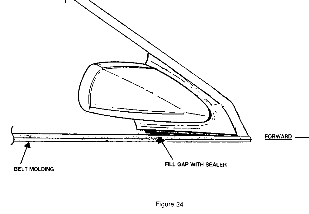
d. Poor fit of filler (rear lower corner) to door at belt line (See Figure 24).
Correction:
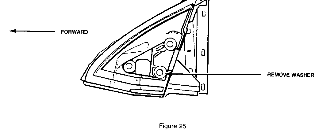
1. Remove mirror. 2. Remove (pry off) spacer washer at rear lower attaching hole area (See Figure 25).
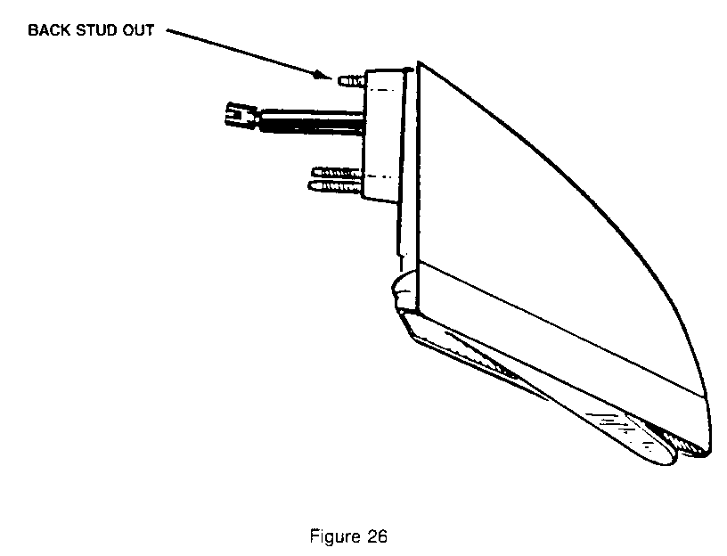
NOTICE: On corrections C and D, if difficulty installing front nut is encountered, back front stud out 2mm (See Figure 26).
4. "A" pillar (windshield to roof area) of door upper frame (See area 4 of Figure 13).
a. Door alignment - door frame outboard of specification
Correction: Adjust header (See Figure 14).
b. Poor seating of glass into glass run channel
Correction Adjust door glass, See 1987 Body Service Manual Doors "C, H" styles 5C-27.
c. Replace run channel, or
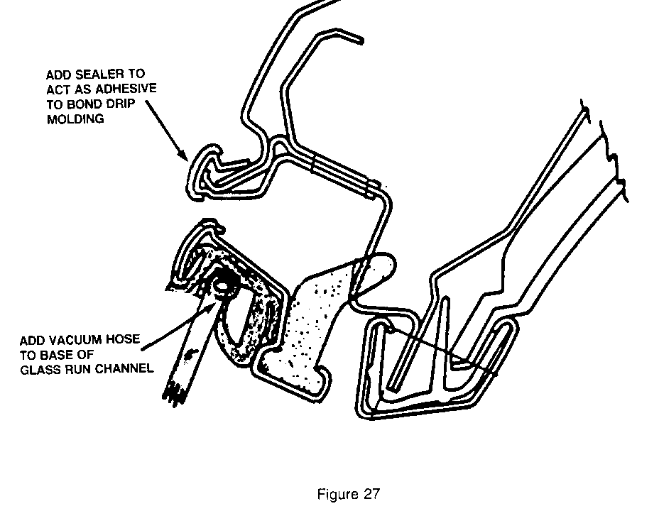
d. If run channel isn't available, add 5/16" outside diameter vacuum hose to glass run channel front upper corner to rear upper corner (See Figure 27).
e. Loose drip moulding
Correction: Apply sealer to act as adhesive (See Figure 27).
C. Rear Door - Specific Areas
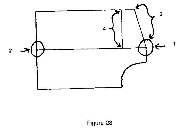
1. Beltline at rear, probable cause (Area 1 of Figure 28).
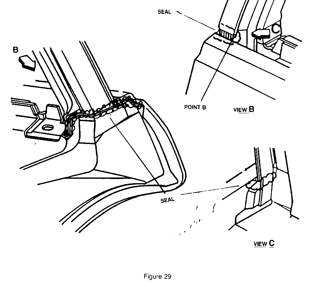
a. Misapplied thumb grade sealer.
Correction: Apply as indicated (See Figure 29).
2. Beltline at front, probable cause (Area 2 of Figure 28).
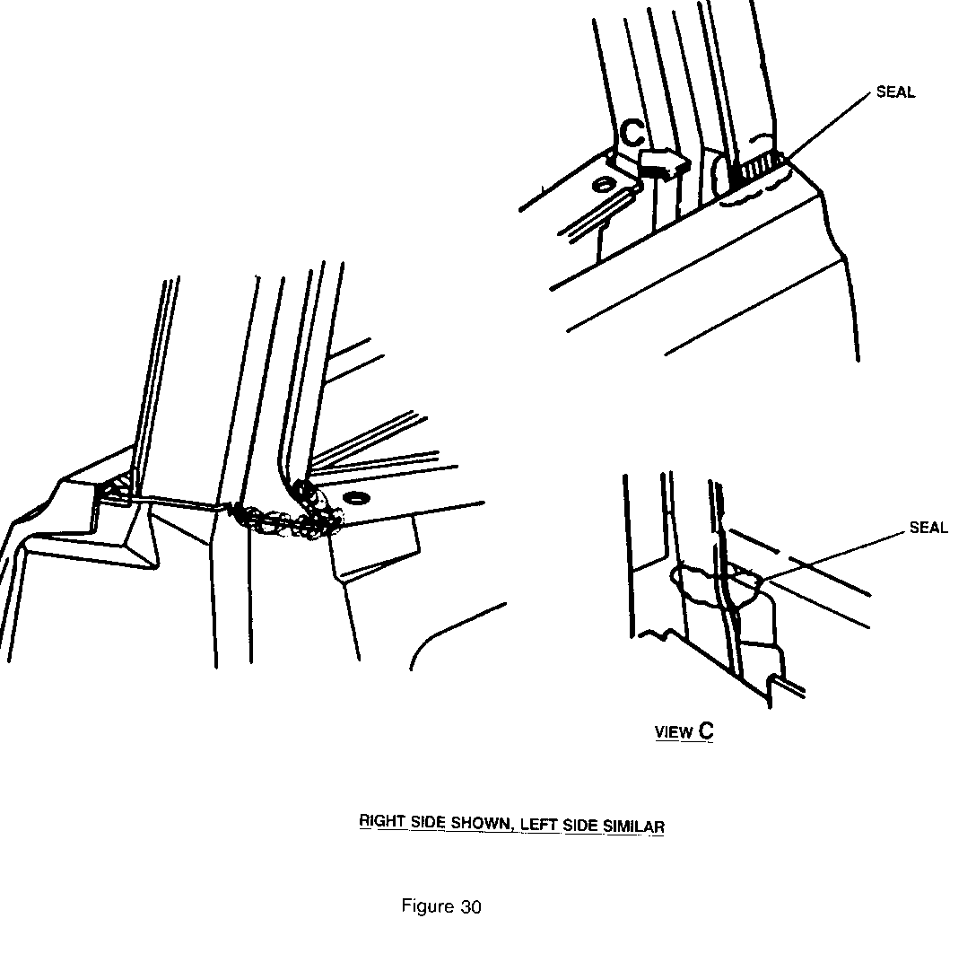
a. Misapplied thumb grade sealer
Correction: Apply as indicated (See Figure 30)
3. Sail area, probable cause (Area 3 of Figure 28).
a. Door alignment - Door frame outboard
Correction: Adjust frame to specifications (See Figure 14).
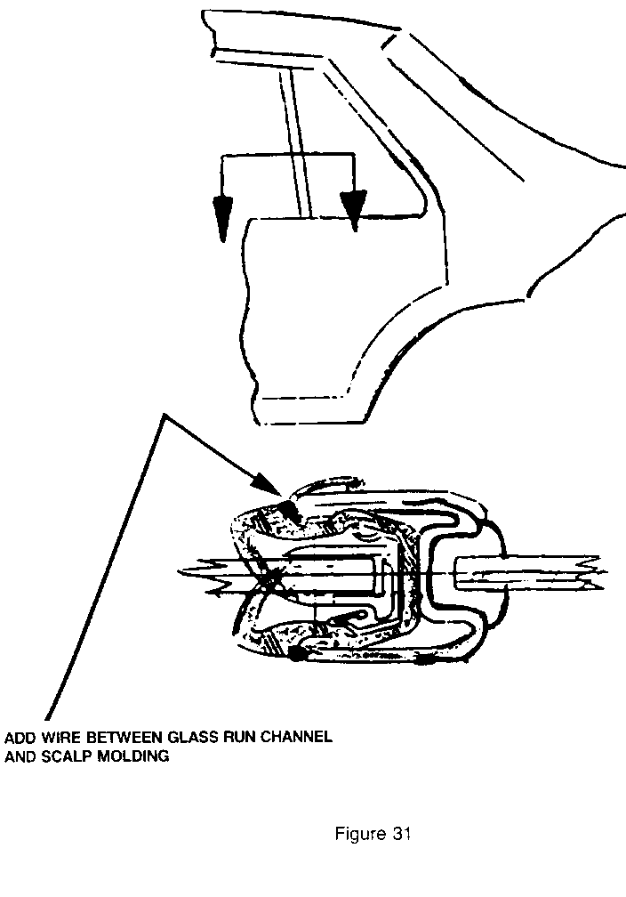
4. Division post, probable cause: Area 4 of Figure 28. Also Figure 31.
a. Poor seal compression to glass
Correction: Add Black Vinyl coated electrical wire (approximately 5/64"-mm outside dimension length, as required). Between glass run channel and scalp moulding (See Figure 31).
D. Back Glass
1. Entire periphery, probable cause:
a. Skip in urethane
Correction: Apply sealer to skip (See Figure 9).
* CADILLAC SPECIFIC BULLETIN TO FOLLOW -------------------------------------
Some 1989 DeVilles and Fleetwoods may experience an objectionable windnoise or wind buffeting at the A-Pillars, windshield header, or door locations. For proper diagnosis and repair of these conditions, use the procedures in this bulletin.
This bulletin is divided into the following three sections:
I. Windnoise diagnosis and testing.
II. Repair of windshield and cowl locations.
III. Repair of door, door glass, and mirror locations.
I. WINDNOISE DIAGNOSIS -------------------
THE WINDNOISE CONDITION
The first step of the repair process in correcting windnoise is to identify the cause(s) of the noise. A determination must be made as to whether the cause of the noise is air escaping from the vehicle or outside air turbulence.
To assist in diagnosing the cause of a windnoise complaint, answers to the following questions should be obtained:
1. What specific noise is objectionable?
A. Whistle B. Flutter C. Rush of air
2. At what speed does the noise occur?
3. Does the noise appear to be:
A. Air leaving the body? (internal windnoise) B. Air passing over the body's exterior surface? (external windnoise)
4. In what general area does the noise appear to originate?
A. Front of the vehicle B. Side of the vehicle
5. Is the heater/AC blower motor ON or OFF?
ANALYZING WINDNOISE
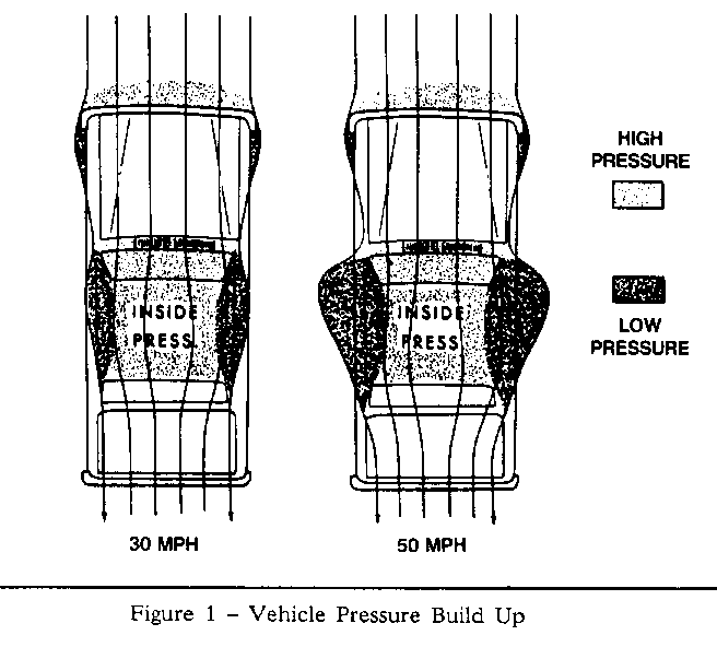
When analyzing windnoise, it is important to understand the forces that act upon the vehicle that can create this condition. As air strikes and bends around the front of a vehicle in motion, it causes a low pressure area to develop around the front pillars and side window locations of the body. At the same time, air flow that is filtered through the vehicle's vents and/or AC system will cause a high pressure to build up inside the passenger compartment. The faster the vehicle is traveling, the greater the pressure difference between the inside and outside of the vehicle becomes. Refer to Figure 1.
This high inside pressure and low outside pressure is separated only by the vehicle's sheet metal panels, glass, weatherstrips, and body seals. When an opening is created at a body seam or weak weatherstrip contact, the high inside pressure will move toward the low outside pressure and create an internal windnoise.
Wind rush or external windnoise is created by the air passing over and around misaligned body components such as vinyl top and windshield mouldings, mirrors, and door mouldings.
THE ROAD TEST
A road test is required to determine if the windnoise condition is external, internal, or a combination of the two.
NOTE: Often there is one primary leak source and one or more secondary leaks that contribute to the noise condition.
Repairing only one of these sources may not completely repair the total condition, but only reduce it.
The following items should be used by the technician during the test drive to aid in locating the leak area:
1. Mechanic's stethoscope or vacuum hose. 2. Masking tape (2" in width). 3. Strip caulk. 4. China marking pencil.
The vehicle should be driven at the speed in which the noise was noticed by the customer or until it is heard. Safe legal speeds should never be exceeded.
If the noise can be heard with the door glass lowered and the vehicle driven, it is EXTERNAL WINDNOISE.
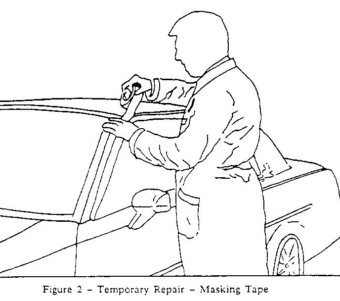
Locating an external windnoise is accomplished by taping off various mouldings and gaps until the noise is eliminated to pinpoint the exact cause of the noise. Refer to Figure 2.
If the noise can only be heard with the windows in a full up position while the car is driven it is INTERNAL WINDNOISE caused by an open body seam or poor glass/door weatherstrip sealing surface.
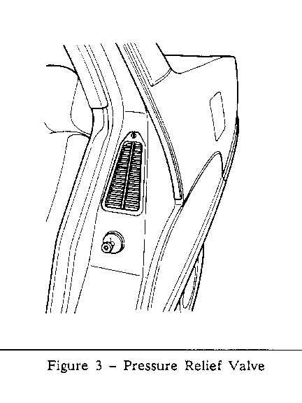
The first step in locating the source of internal windnoise is to tape off the pressure relief valves. Refer to Figure 3. This will cause the air pressure to build up inside the vehicle and enhance the windnoise while driving. Trace the suspected area with the stethoscope or section of vacuum hose to locate the leak area.
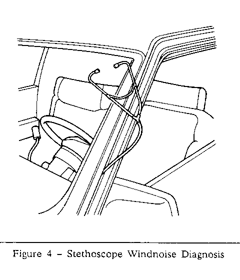
NOTE: Poor seals that cause internal windnoise can also be located in the shop by taping off the pressure relief valves and turning the blower motor on high to pressurize the vehicle. Next, trace the suspected areas with a stethoscope from the outside of the vehicle as shown in Figure 4.
With the suspected windnoise locations diagnosed, refer to the sections of this bulletin for the proper repair procedure of that area.
II. REPAIR OF WINDSHIELD AND COWL LOCATIONS --------------------------------------- Possible areas of concern covered in this section are:
INTERNAL WINDNOISE
1. Base of the A-Pillar. 2. Windshield sealer voids.
EXTERNAL WINDNOISE
1. Windshield lace. 2. Vinyl top mouldings.
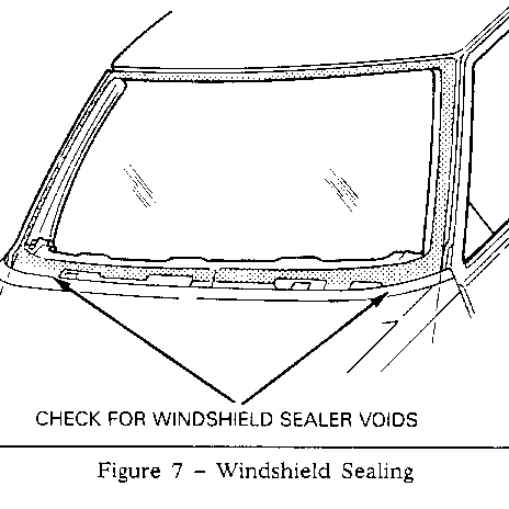
Some DeVilles or Fleetwoods may exhibit excessive internal windnoise at the base of the windshield pillars and door area. First, check the door weatherstrip primary and secondary seal to the body. Refer to Section III of this bulletin. If these seals are OK, use the following procedures to seal the base of the A-Pillar and check for voids in the windshield sealer.
1. Remove the windshield lower reveal moulding.
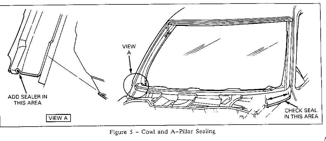
2. Apply 3M strip-caulk, P/N 08578 or equivalent, thumb-grade sealer to the open seams at the base of the A-Pillar as shown in Figure 5.
3. Remove the A-Pillar weatherstrip and inspect the pinch weld flange it mounts to, also inspect the seam at the base of the cowl area as shown in Figure 5. Apply thumb-grade sealer to these areas if these seams appear to be open.
4. Repeat the above operations on the opposite side of the vehicle.
5. Check the seal at the base of the windshield as shown in Figure 6 with compressed air and soapy water test. Apply compressed air at no more than 30 psi (205 KPa) to the base of the windshield from the inside of the vehicle toward the outside as shown in Figure 7.
6. If voids in the windshield are located, reseal with Urethane adhesive kit, GM P/N 9636067 or equivalent.
7. Reinstall lower reveal moulding.
To seal the base of the pillar and windshield use most applicable Labour operation and time from the Canadian Labour Time Guide.
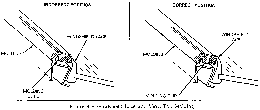
Some vehicles may exhibit excessive external windnoise in the windshield and windshield pillar areas, which can be caused by poor seal of the windshield lace to the body or a mispositioned vinyl top moulding.
First, proper diagnosis must be made by taping off the suspected areas to eliminate the windnoise and isolate the cause. With the suspected area identified, use the following procedures to correct the condition:
VINYL TOP MOULDING
1. Check the position of the vinyl top moulding to the windshield lace in the windshield pillar area. The correct position of the vinyl top moulding is tucked under the windshield lace as shown in Figure 8.
2. If the vinyl top moulding does not tuck under the windshield lace, then remove the moulding and replace the moulding clip with P/N 20199675.
NOTE: It may be necessary to apply heat to the windshield lace using a heat gun to increase the flexibility of the lace and aid in positioning the lace and moulding correctly.
Use most applicable Labour Operation from the Canadian Labour Time Guide.
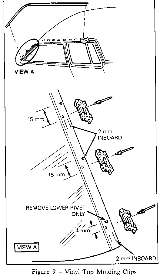
It may be necessary to relocate the moulding inboard on one or both sides of the vehicle to obtain a correct relationship of the vinyl top moulding to the windshield lace. Use the following procedure to relocate the vinyl top moulding:
1. Remove the moulding and moulding clips from the vehicle.
2. For the centre and top clip, drill a 3/32" hole 15mm below and 2mm inboard of the existing clip rivet as shown in Figure 9.
NOTE: Do not remove the old rivets.
3. Remove the lower rivet and apply sealer to exposed hole. Drill a 3/32" hole 4mm below and 2mm inboard of the existing rivet location.
4. Prime all exposed rivet holes with a zinc-rich primer.
5. Rivet moulding clip in the new locations.
6. Reinstall vinyl top moulding.
Use most applicable Labour Operation and time from the Canadian Labour Time Guide.
NOTE: It may be necessary to apply heat to the windshield lace using a heat gun to increase the flexibility of the lace and aid in positioning the lace and moulding correctly.
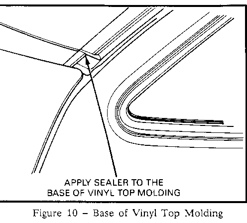
7. Apply 3M strip-caulk, P/N 08578 or equivalent, thumb-grade to the base of the moulding as shown in Figure 10.
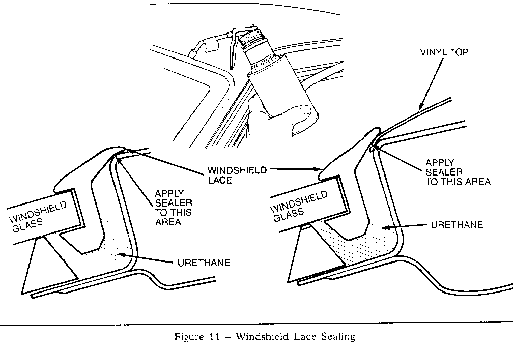
8. Apply sealer to the windshield lace as explained in the following steps:
WINDSHIELD LACE
1. Apply 3M Windo-weld resealant, P/N 08633 or equivalent, flow-grade sealer under the windshield lace as shown in Figure 11.
2. Clean off excessive sealer and road test vehicle.
Use most applicable Labour Operation and time from the Canadian Labour Time Guide.
III. REPAIR OF DOOR LOCATIONS ------------------------ Possible areas of concern in this section are: 1. Door alignment. 2. Door weatherstrips. 3. Door glass. 4. Mirrors.
DOOR ALIGNMENT AND DOOR WEATHERSTRIPS
If an internal windnoise is diagnosed in the front or rear door locations, use the following procedures to correct this condition.
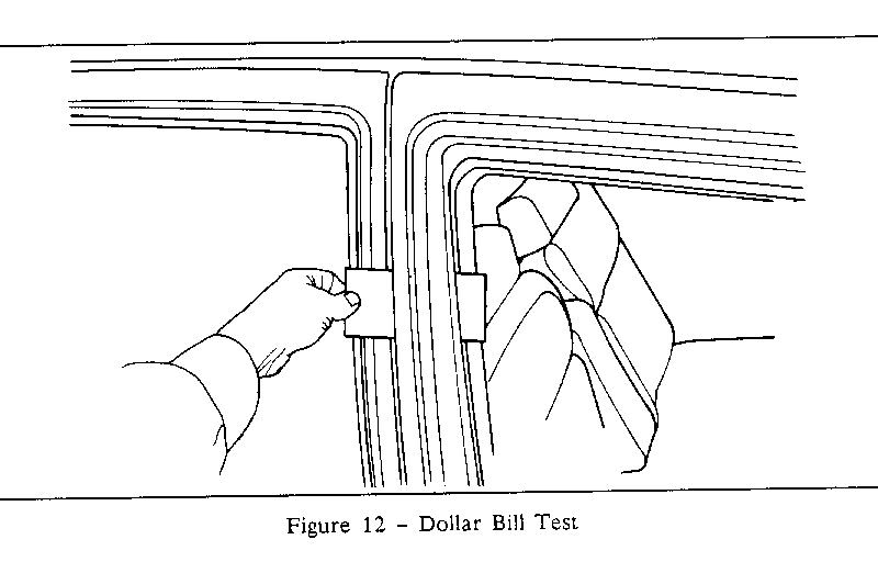
1. Check door weatherstrip contact at both primary and secondary weatherstrips around the entire door perimeter with a dollar bill as shown in Figure 12.
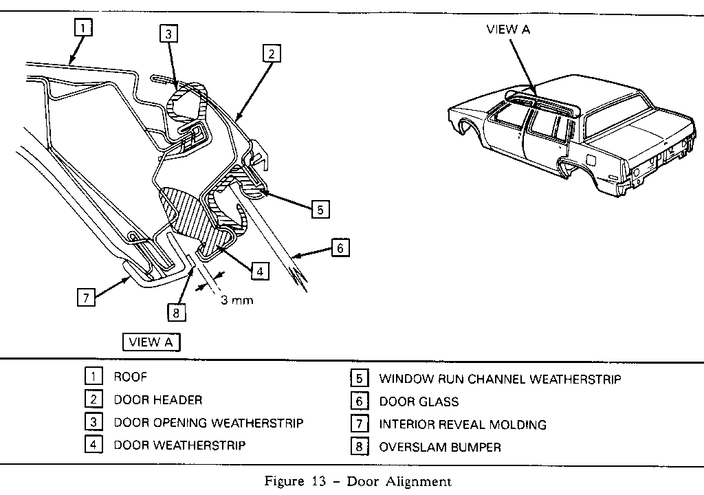
The door opening weatherstrip should have uniform contact along its entire length to both front and rear doors, and the door weatherstrip should have a uniform contact to the body as shown in Figure 13. Also, the gap between the door over-slam bumper (located on the interior reveal moulding in the B-Pillar area) and the door should be 3mm with the door in a full closed position. Refer to item number 8 in Figure 13.
2. If door weatherstrip contacts are poor or the gap to the over-slam bumper is wide, adjust the door(s) inboard.
NOTE: Door adjustments may require moving both upper and lower half of the door inboard.
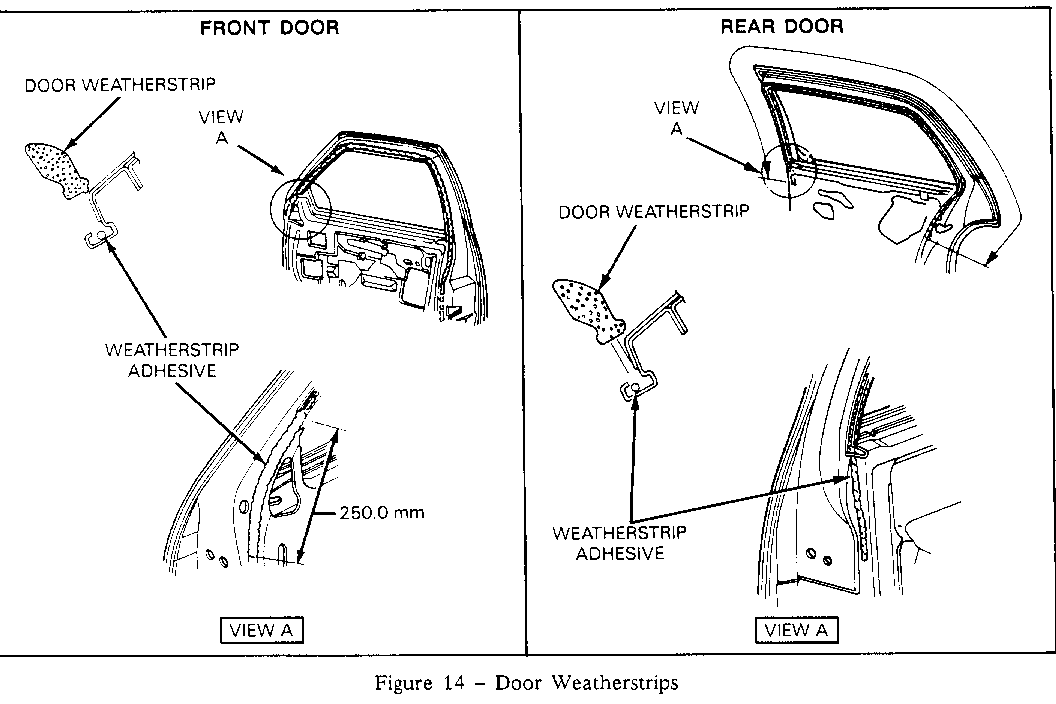
3. Inspect the door weatherstrip for proper alignment and installation to the door. The weatherstrips should be secured with both push-type fasteners and adhesive from the base of the header to the upper door hinge in the front and to the door lock in the rear of the door as shown in Figure 14. If required, apply weatherstrip adhesive, GM P/N 12345096 or 3M P/N 08011, to these areas.
Use most applicable Labour Operation and time from the Canadiaon Labour Time Guide.
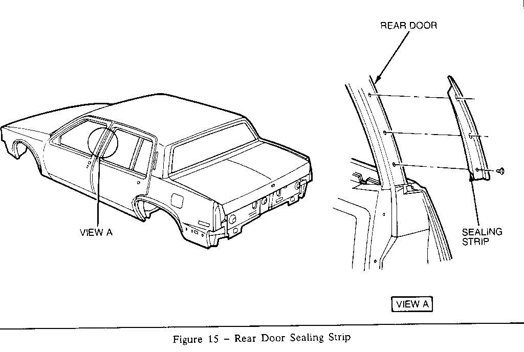
4. Inspect the sealing strip between front and rear doors for proper contact to the front door as shown in Figure 15. Adjust seal as required.
DOOR GLASS
If an internal windnoise is diagnosed in the front door glass area, use the following procedure to correct this condition:
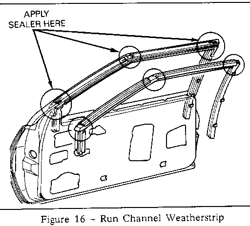
1. Remove the door glass run channel weatherstrip and apply a bead of 3M strip-caulk, P/N 08578, to the areas shown in Figure 16.
2. Reinstall the run channel weatherstrip and clean off any excess sealer.
Use most applicable labour operation and time from the Canadian Labour Time Guide.
MIRRORS
If an internal or external windnoise condition is diagnosed in the outside mirror location, use the following procedures to correct this condition.
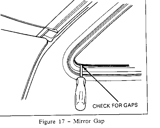
1. Inspect for gaps or misalignment between the mirror and the door as shown in Figure 17.
2. If the mirror is gapped or misaligned to the door, remove the interior trim and the three 10mm nuts retaining the mirror to the door.
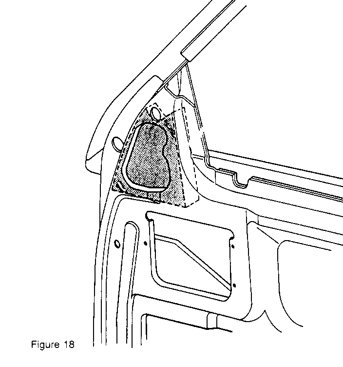
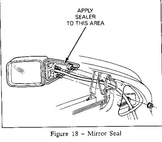
3. Apply a sealing strip of Kent Products 1/4" x 5/32" adhesive-back foam, shim stock P/N 40105, to the surface of the mirror as shown in Figure 18.
4. Apply strip-caulk, P/N 08578, over three mirror retaining studs to seal studs to door.
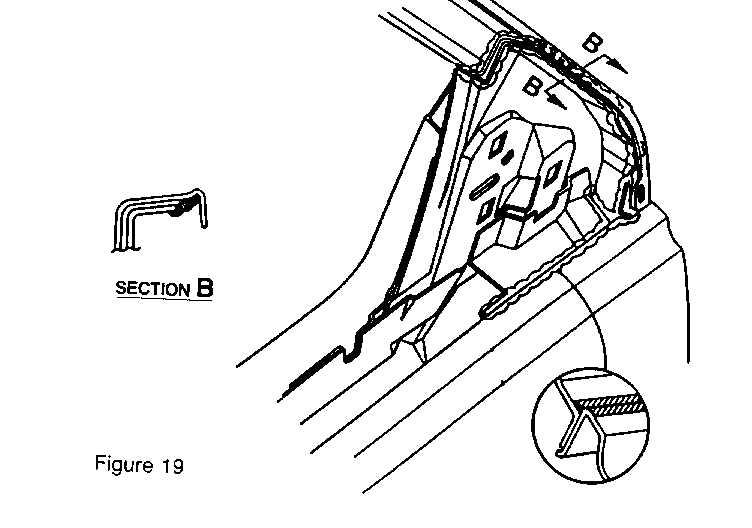
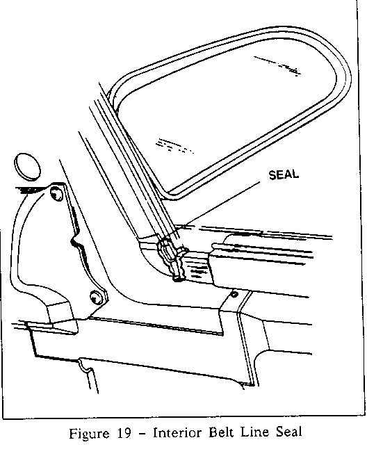
5. Inspect the locations shown in Figure 19 and apply 3M strip-caulk if needed.
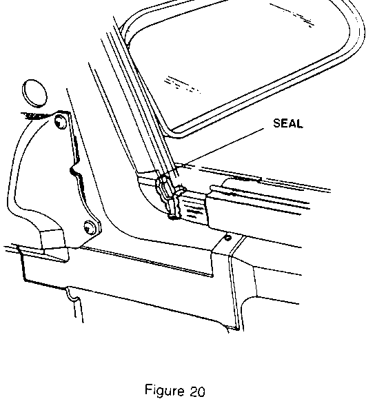
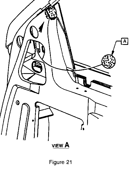
6. Correctly install the foam filler plug shown in Figure 20.
7. Install interior trim.
Use most applicable labour operation and time from the Canadian Labour Time Guide.
General Motors bulletins are intended for use by professional technicians, not a "do-it-yourselfer". They are written to inform those technicians of conditions that may occur on some vehicles, or to provide information that could assist in the proper service of a vehicle. Properly trained technicians have the equipment, tools, safety instructions and know-how to do a job properly and safely. If a condition is described, do not assume that the bulletin applies to your vehicle, or that your vehicle will have that condition. See a General Motors dealer servicing your brand of General Motors vehicle for information on whether your vehicle may benefit from the information.
