SERVICE MANUAL UPDATE-SEC.8A ELECT. SYS/ELECT DIAG REVISION

SUBJECT: ELECTRICAL SYSTEMS/SERVICE MANUAL UPDATE - ELECTRICAL DIAGNOSTIC REVISIONS
MODELS AFFECTED: 1992 LESABRE 1992 PARK AVENUE/ULTRA
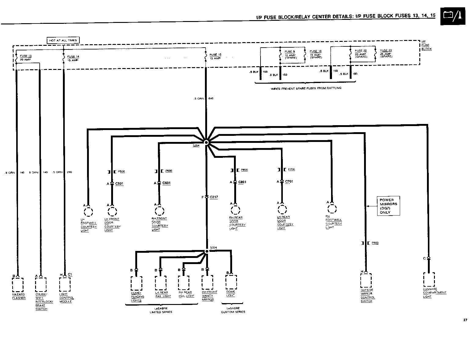
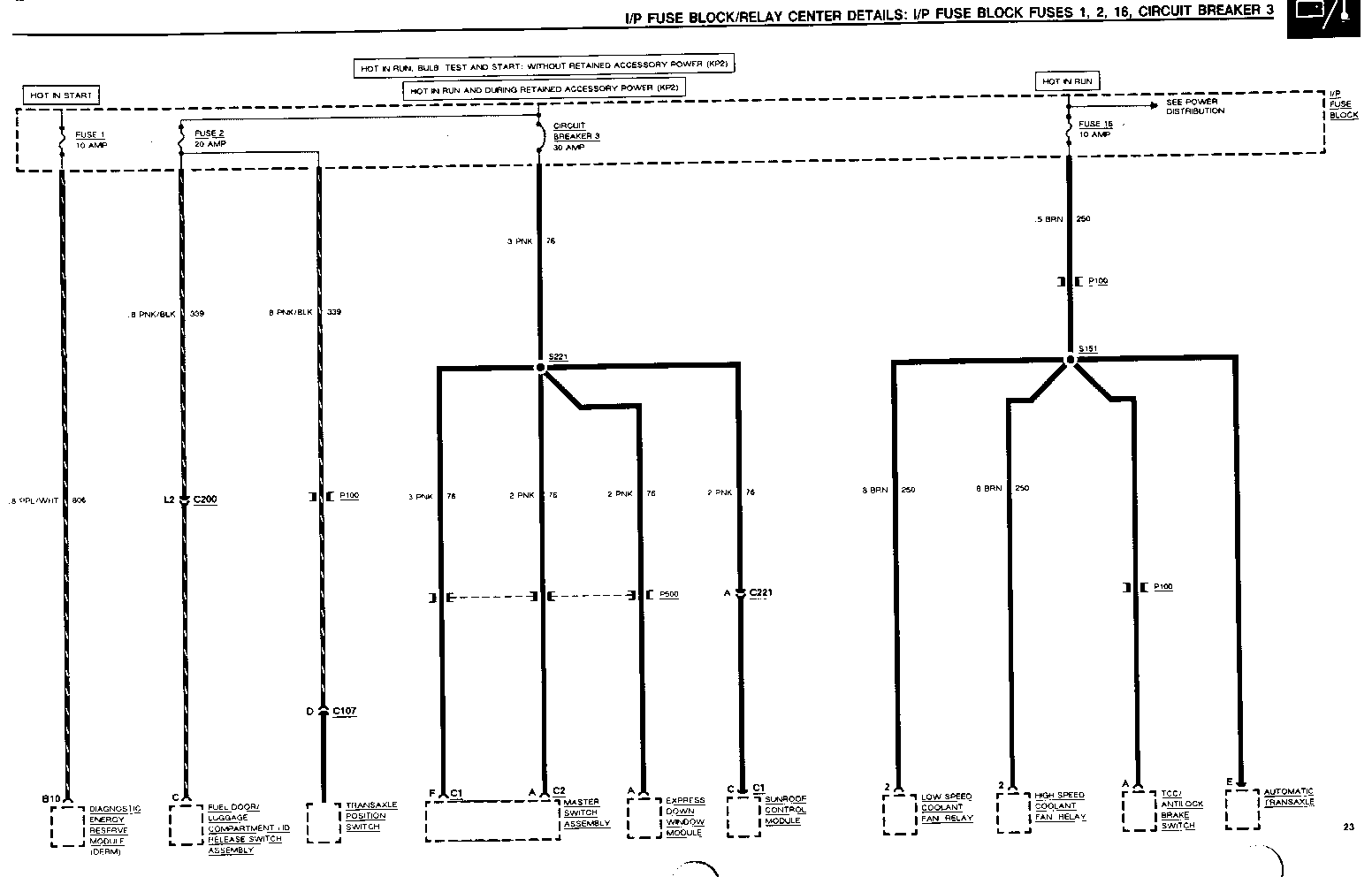
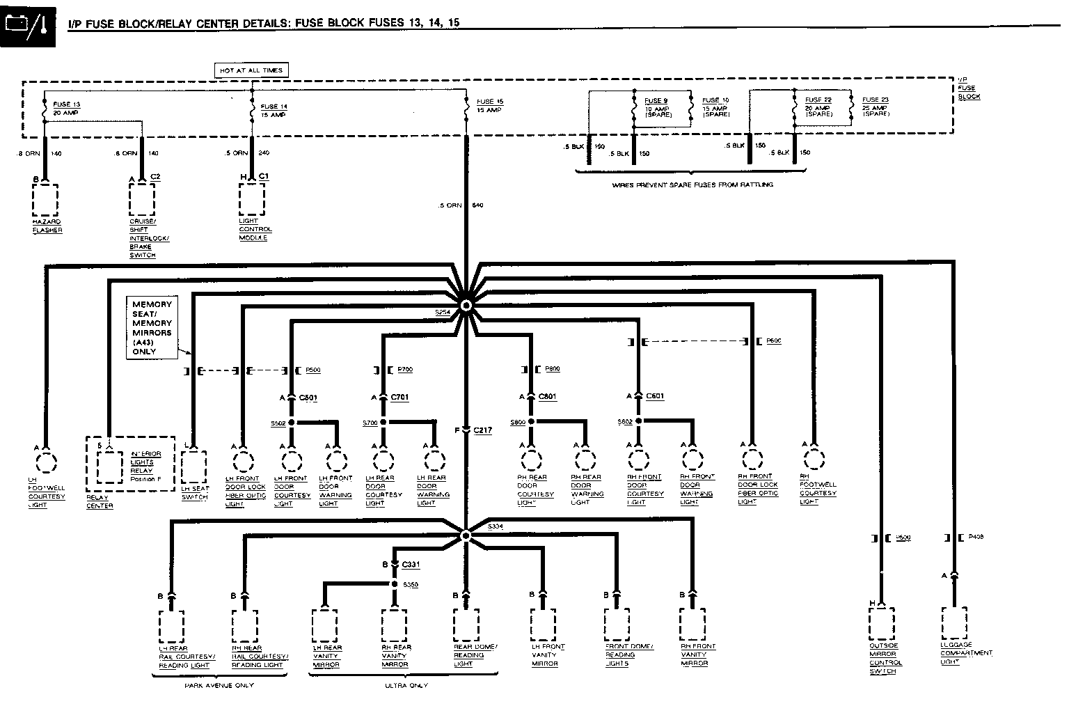
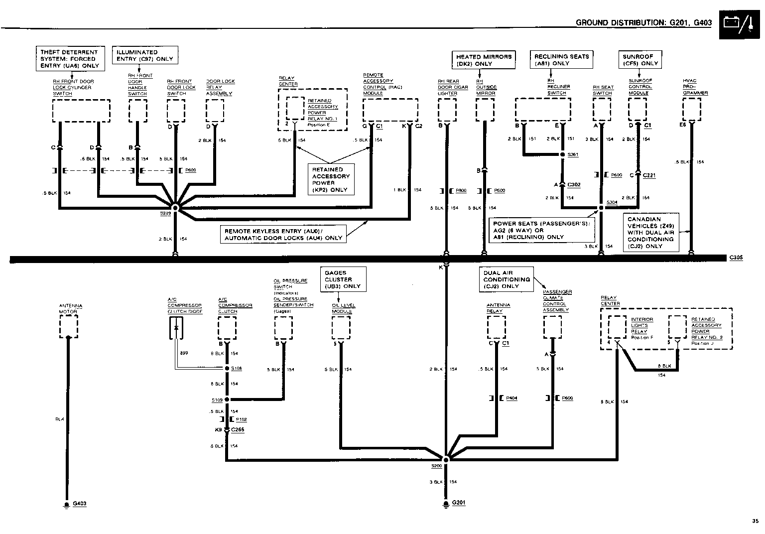
This bulletin provides LATE PRODUCTION AND DESIGN INFORMATION ranging from wire gauge and color changes to changing connector pinout identification and wiring routing changes.
The following information reflects current changes and revisions to the Electrical Systems/Service Manual Diagnostic Procedures.
Please update your Service Manual accordingly.
UPDATE CHANGE SUMMARY
CARLINE: BUICK LeSABRE LIMITED/LeSABRE CUSTOM --------------------------------------------- Page(s) Revision ------- -------- 36, 328 Change the .5 BLK (154) wire between the Door Lock Relay Assembly and Splice S289 to 2 BLK (154).
CARLINE: BUICK PARK AVENUE/PARK AVENUE ULTRA -------------------------------------------- Page(s) Revision ------- -------- 402 Change "Check Relay Center Fuse 1 and related wiring." in the Diagnosis column to "Check Relay Center Fuse 2 and related wiring."
OPERATION:
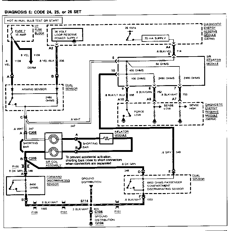
---------- The DERM tests the Deployment Loop (both Sensors, Inflator Module, Ignition Feed, and Reserve Power Supply) by measuring voltage through the SIR Resistor Module. The DERM stores one of the codes if it senses an out of range condition. Each of the codes is set when a particular condition is detected.
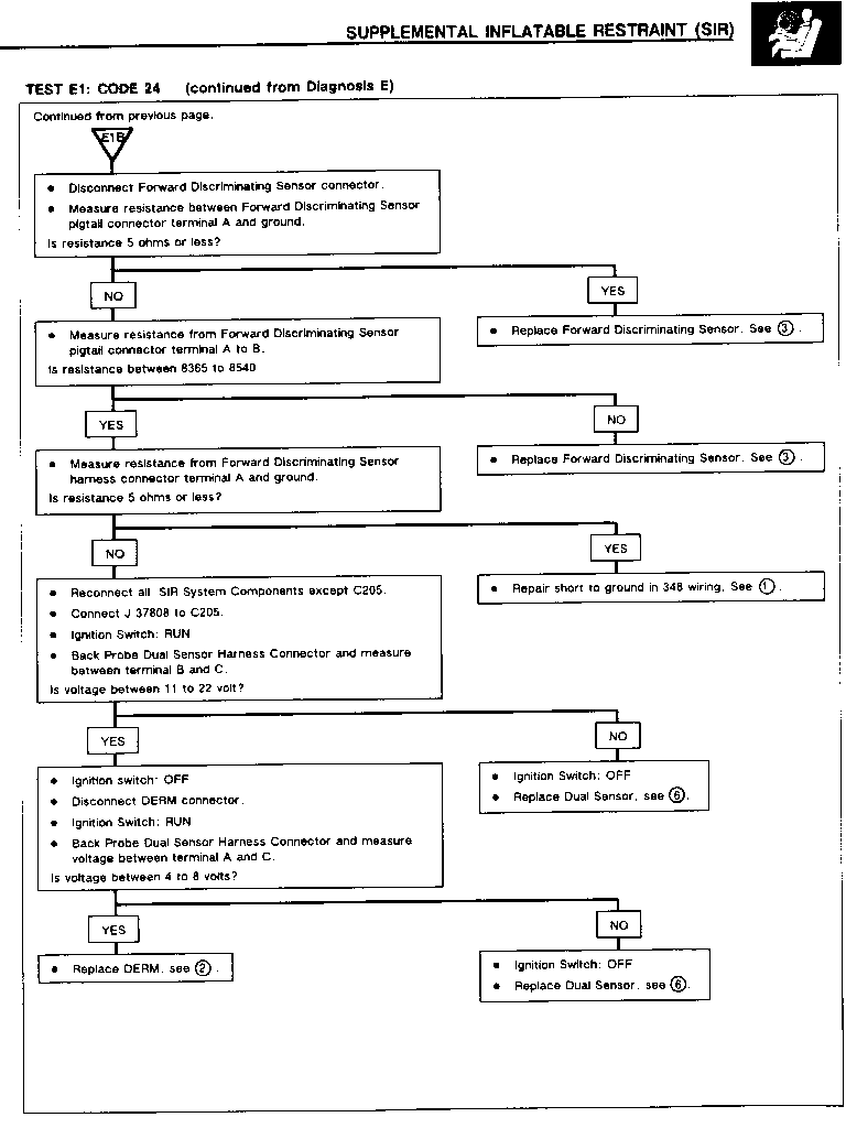
-Code 24 - Voltage at DERM terminal A6 is between 0 and 41% of Reserve Power Supply voltage for 500 Milliseconds.
-Code 25 - Voltage at DERM terminal A6 is within 2 volts of Battery.
-Code 26 - Voltage difference between DERM terminal A6 and A7 greater than 0.45 volts.
POSSIBLE CAUSES
Code 24 - Low resistance in Dual Sensor. Improper resistance in either Discriminating Sensor. 347, 348, 349, 688, 714, 752 or 753 wires shorted battery or ground. 347 or 752 wire open.
Code 25 - Steering column wiring shorted to ignition or battery. 344 or 347 wires shorted to ignition. High resistance in SIR Resistor Module.
Code 26 - Open or high resistance connection in steering column wiring. Short between 236 and 753 wires. 347, 348, 349 wires open. Faulty Dual Sensor or SIR Resistor Module.
SERVICE PARTS INFORMATION
SERVICE PARTS CATALOG COMPONENT Reference Name Group --------- -------------- ----- FASTEN BELTS INDICATOR GAGES BULB (PC 161) INDICATORS BULB (PC 74)
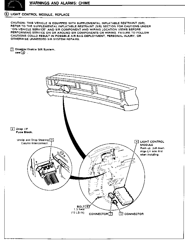
IGNITION KEY WARNING SWITCH See Chassis Service Manual Section 3F. LH FRONT DOOR LOCK ASSEMBLY LOCK, FD 10.470 LIGHT CONTROL MODULE MODULE, HDLP AUTO CONT 2.485
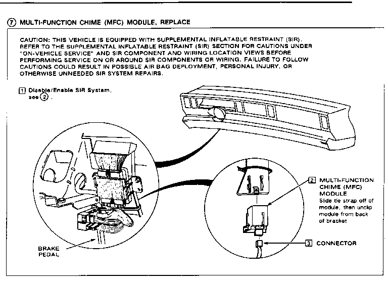
MULTI-FUNCTION CHIME (MFC) MODULE MODULE, M/FUNC ALARM 2.195 POWERTRAIN CONTROL MODULE (PCM) CONTROLLER, ECM 3.670A SAFETY BELT SWITCH BELT ASM, D/SEAT RETR 14.875
General Motors bulletins are intended for use by professional technicians, not a "do-it-yourselfer". They are written to inform those technicians of conditions that may occur on some vehicles, or to provide information that could assist in the proper service of a vehicle. Properly trained technicians have the equipment, tools, safety instructions and know-how to do a job properly and safely. If a condition is described, do not assume that the bulletin applies to your vehicle, or that your vehicle will have that condition. See a General Motors dealer servicing your brand of General Motors vehicle for information on whether your vehicle may benefit from the information.
