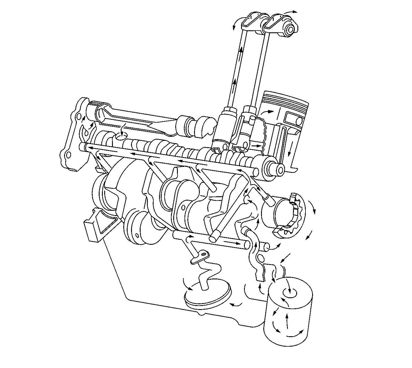
The engine lubrication system is of the force-feed type. This means that oil is supplied under full pressure to the crankshaft, connecting rods, valve lifters, camshaft and rear balance shaft bearing. It also means that a controlled volume of oil is supplied to the rocker arms and push rods. All other moving parts are lubricated by gravity flow or splash. The supply of oil is carried in the lower crankcase (oil pan) which is filled through a filler opening in the rocker arm cover. A removable oil level indicator rod on the left side of the crankcase is provided to check the oil level. The oil pump is located in the front cover and is driven by the crankshaft. It is a gerotor style pump which is a combination of gear and rotor pumps. It is connected by a passage in the cylinder crankcase to an oil screen housing and pipe assembly. The screen is submerged in the oil supply and has ample volume for all operating conditions. If the screen becomes clogged, oil may be drawn into the system through the relief valve in the screen. Oil is drawn into the pump through the screen and pipe assembly, and a passage in the crankcase, connecting to the passages in the front cover. All oil is discharged from the pump to the oil pump filter adapter assembly. The assembly consists of an oil filter bypass valve and a nipple for installation of an oil filter. The spring loaded oil pressure relief valve located in the timing chain cover, limits the oil pressure. The oil filter bypass valve opens when the filter has become restricted to the extent that approximately 68.95 kPa (10 psi) of pressure difference exists between the filter inlet and discharge, to by-pass the oil filter and channel unfiltered oil directly to the main oil galleries of the engine. A full flow oil filter is externally mounted to the oil filter adapter on the lower right front side of the engine. If the filter element becomes restricted, not allowing engine oil to pass through, a spring loaded bypass valve opens. The main oil galleries run the full length of the crankcase and cut into the valve lifter guide holes in order to supply oil at full pressure to the lifters. Holes drilled from the crankshaft bearings to the main gallery intersect the cam bearing bores in order to supply oil to the cam bearings.
Oil is carried from the crankshaft bearings to the connecting rod bearings through holes drilled in the crankshaft. Pistons and cylinder walls are lubricated by oil thrown off the crankshaft and by connecting rod splash. Piston pins are lubricated by splash.
Each rocker arm and valve is supplied with oil through the tubular push rod. This oil comes from the inside of the lifter, passing around the metering valve and through a hole in the lifter push rod seat. Oil from the push rod passes through a hole in the lifter push rod seat, and emerges on top of the push rod seat boss.
