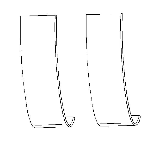
Engine bearings are precision insert bearings, which are
available for service use in standard and 0.001 in undersize.
Notice: Do not scrape, shim, or file bearing inserts. If the bearing surface
of the insert is touched with bare fingers, the skin oil and acids will etch
the bearing surface.

- Inspect the bearing surfaces for the following conditions:
| • | Embedded foreign material |
| - | If foreign material is present, determine the nature and the source
of the foreign material. |
| - | Inspect the oil pan sludge and residue. |
| • | Uneven side-to-side wear, resulting from a bent crankshaft or
tapered bearing journals. |
- Inspect the outer surfaces for the following conditions:
| • | Spot wear, resulting from insert movement or high spots in the
surrounding material |
| • | Discoloration, resulting from overheating |
| • | Flattened tangs and wear grooves, resulting from looseness or
rotation |
Important:
| • | Carefully inspect bearing failure, other than normal wear. |
| • | Inspect the crankshaft or the connecting rod and the bearing bores. |
| • | Use the following procedure, in order to inspect the connecting
rods or main bearing bores: |
| • | Torque the bearing cap to specifications. |
| • | Measure the bore for taper and out of round. |
| • | Ensure that taper or out of round does not exist. |
- Inspect the thrust surfaces of the main thrust bearing for the following
conditions:
| • | Grooving, as a result of irregularities in the crankshaft thrust
surface |
| • | Refer to Crankshaft and Bearings Clean and Inspect
. |
- Inspect the bearing cap bolts.
| • | In order to determine if a bolt is stretched, compare it to a
new bolt. |
| • | Replace the bearing cap bolts, as necessary. |
Bearing Clearance
In order to determine the correct replacement insert size, accurately
measure the bearing clearance. Use either of the following methods to measure
the bearing clearance however, the first method gives more reliable results
than the second method.
- This method yields measurements from which to compute the bearing
clearance.
| 1.1. | Measure the crankshaft journal diameter, in several places, approximately
90° apart. |
| 1.2. | Average the crankshaft journal diameter measurements. |
| 1.3. | Measure the taper and runout. |
| 1.4. | With the bearing inserts installed in the correct bore and torqued
to specification, measure the bearing insert ID with an inside micrometer. |
| 1.5. | If new inserts are replacing the inserts, measure after installing
the new inserts. |
| 1.6. | Select a suitable set of inserts, if the readings are within limits. |
| • | Bearing sets are available in standard and undersize, in order
to keep clearances within the limits. |
| • | Replace the crankshaft if the clearances cannot be brought into
specifications. |
- This method yields the bearing clearance directly, however it
does not give any indication of bearing or journal runout.
| 2.1. | Install all of the bearing inserts into the block. |
| 2.2. | Install the crankshaft into the block. |
| 2.3. | Place a piece of gauging plastic across the entire bearing width. |
| 2.4. | Seat the bearing cap carefully, by tapping it lightly with a suitable
tool. |
| | Important: Do not rotate the crankshaft.
|
| 2.5. | Torque the bearing cap bolts to specification. |
| 2.6. | Remove the bearing cap, leaving the gauging plastic in place,
regardless of whether the gauging plastic adheres to the journal or to the
bearing cap. |
| 2.7. | Measure the flattened gauging plastic, at its widest point, with
the scale printed on the gauging plastic package. |
| 2.8. | Remove all traces of the gauging plastic after measuring. |
Bearing Installation
Notice: Do not scrape, shim, or file bearing inserts. If the bearing surface
of the insert is touched with bare fingers, the skin oil and acids will etch
the bearing surface.
Important: Ensure that the bearing cap bolt hole and the cap mating surfaces are
clean and dry.
- Dip the bearing cap bolts in clean engine oil.
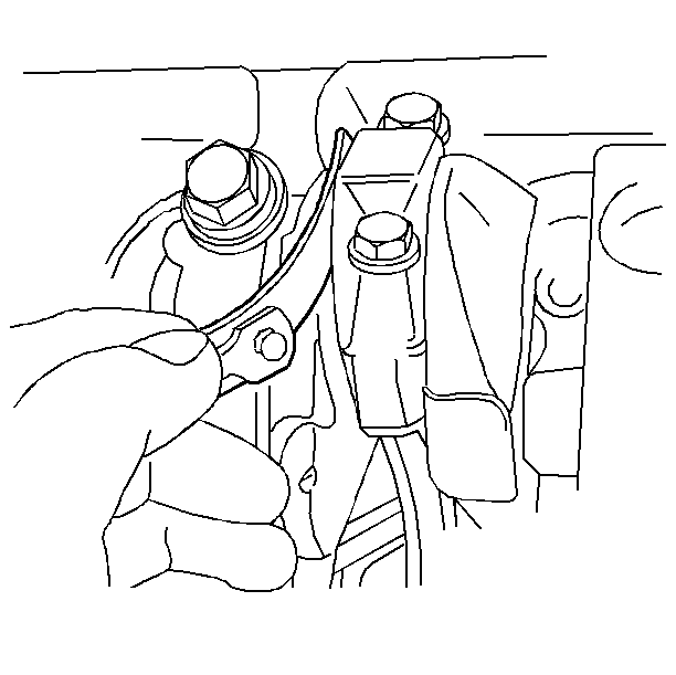
- Place the inserts into the bearing cap and into the connecting
rod.
| • | The inserts will project slightly when put into place. Ensure
that they project an equal distance on both sides. |
| • | Ensure the engagement of the insert tangs. |
Notice: Upper and lower inserts may be different. Do not obstruct any oil passages.
- When using a thrust bearing main bearing insert, coat the thrust surface
with GM-approved lubricant or equivalent.
- Lubricate the bearing surface with clean engine oil.
- Install the connecting rod.
- Install the bearing cap, by tapping the cap gently into place
with a suitable tool.
- Install the bearing cap bolts.
Tighten
Tighten the bolts to 35 N·m +45 degrees (26 lb ft
+50 degrees).
Notice: Use the correct fastener in the correct location. Replacement fasteners
must be the correct part number for that application. Fasteners requiring
replacement or fasteners requiring the use of thread locking compound or sealant
are identified in the service procedure. Do not use paints, lubricants, or
corrosion inhibitors on fasteners or fastener joint surfaces unless specified.
These coatings affect fastener torque and joint clamping force and may damage
the fastener. Use the correct tightening sequence and specifications when
installing fasteners in order to avoid damage to parts and systems.
- Pry the connecting rods back and forth, in order to check for
binding.
- If necessary, loosen and retighten the bearing cap.

- Measure the connecting rod side clearance.


