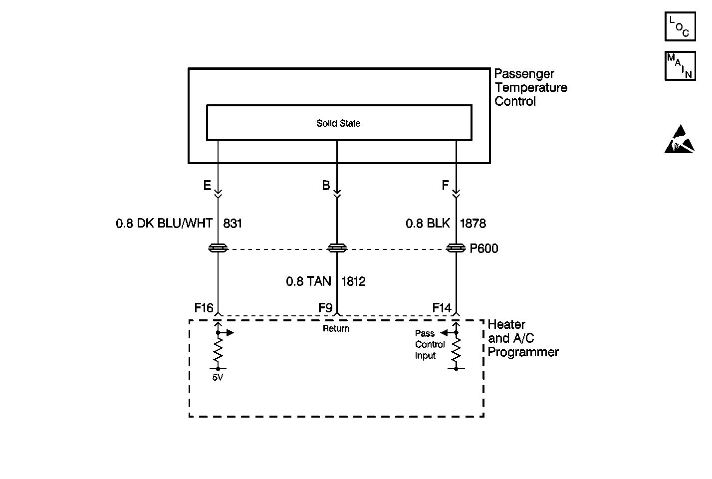
DTC 036 Pass Control Assy Feedback Out of Range Buick

Circuit Description
The passenger temperature control assembly receives voltage signals from the HVAC programmer. The signal voltage will vary from 5 volts (open circuit) to 0 volts (short circuit).
Conditions for Setting the DTC
| • | The ignition is ON. |
| • | The circuit is open or shorted. |
Action Taken When the DTC Sets
Code 036 is set.
Conditions for Clearing the DTC
| • | Using a Scan Tool . |
| • | A history DTC will clear when 40 consecutive IGN cycles without a malfunction. |
| • | HVAC battery voltage is interrupted. |
Test Description
Step | Action | Value(s) | Yes | No |
|---|---|---|---|---|
Refer to Testing for Continuity in Wiring Systems. Is the resistance near the specified range? | 1 K ohms | Go to Step 2 | Go to Step 14 | |
2 |
Refer to Testing for Continuity in Wiring Systems. Is the resistance near the specified range? | 5 K ohms | Go to Step 3 | Go to Step 14 |
3 |
Refer to Testing for Continuity in Wiring Systems. Is the resistance near the specified range? | 9 K ohms | Go to Step 4 | Go to Step 14 |
4 |
Refer to Measuring Voltage in Wiring Systems. Does the voltage equal the specified value? | 5 V | Go to Step 5 | Go to Step 6 |
5 |
Did the DTC Reset? | -- | Go to Step 16 | Go to Intermittents and Poor Connections |
6 | Is the voltage greater than the specified value? | 5 V | Go to Step 7 | Go to Step 8 |
7 | Repair the short to battery in CKT 831. Refer to Wiring Repairs in Wiring Systems. Is the repair complete? | -- | System OK | -- |
8 | Measure the voltage between passenger temperature control harness connector terminal A and DLC terminal 4. Refer to Measuring Voltage in Wiring Systems. Is voltage present? | -- | Go to Step 9 | Go to Step 10 |
9 | Measure the voltage between passenger temperature control harness connector terminal B and DLC terminal 4. Refer to Measuring Voltage in Wiring Systems. Is the specified voltage present? | 5 V | Go to Step 11 | Go to Step 13 |
10 | Measure the voltage between HVAC programmer terminal F16 and DLC terminal 4. Refer to Measuring Voltage in Wiring Systems. Is the specified voltage present? | 5 V | Go to Step 15 | Go to Step 16 |
11 | Repair the open in CKT 1812. Refer to Wiring Repairs in Wiring Systems. Is the repair complete? | -- | System OK | -- |
12 | Repair the short in CKT 1812. Refer to Wiring Repairs in Wiring Systems. Is the repair complete? | -- | System OK | -- |
13 | Check for continuity between the passenger temperature control harness connector terminal B and HVAC programmer connector terminal F9. Refer to Testing for Continuity in Wiring Systems. Is continuity present? | -- | Go to Step 16 | Go to Step 11 |
14 | Replace the passenger temperature control assembly. Refer to Control Assembly Replacement - Passenger . Is the replacement complete? | -- | System OK | -- |
15 | Repair an open in CKT 831 (DK BLU/WHT). Refer to Wiring Repairs in Wiring Systems. Is the repair complete? | -- | System OK | -- |
16 |
Refer to Intermittents and Poor Connections Diagnosis in Wiring Systems. Is the replacement complete? | -- | System OK | -- |
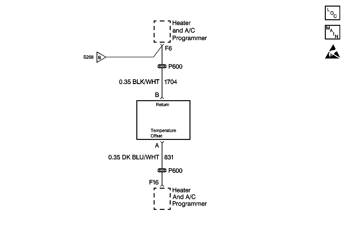
DTC 036 Pass Control Assy Feedback Out of Range Oldsmobile

Circuit Description
The passenger temperature control assembly receives voltage signals from the HVAC programmer. The signal voltage will vary from 5 volts (open circuit) to 0 volts (short circuit).
Conditions for Setting the DTC
| • | The ignition is ON. |
| • | The circuit is open or shorted. |
Action Taken When the DTC Sets
Code 036 is set.
Conditions for Clearing the DTC
| • | Using a Scan Tool . |
| • | A history DTC will clear when 40 consecutive IGN cycles occurred without a malfunction. |
| • | HVAC battery voltage is interrupted. |
Test Description
Step | Action | Value(s) | Yes | No |
|---|---|---|---|---|
Refer to Testing for Continuity in Wiring Systems. Is the resistance near the specified range? | 1 K ohms | Go to Step 2 | Go to Step 14 | |
2 |
Refer to Testing for Continuity in Wiring Systems. Is the resistance near the specified range? | 5 K ohms | Go to Step 3 | Go to Step 14 |
3 |
Refer to Testing for Continuity in Wiring Systems. Is the resistance near the specified range? | 9K ohms | Go to Step 4 | Go to Step 14 |
4 |
Refer to Measuring Voltage in Wiring Systems. Does the voltage equal the specified value? | 5 V | Go to Step 5 | Go to Step 6 |
5 |
Did the DTC Reset? | -- | Go to Step 16 | Go to Intermittents and Poor Connections |
6 | Is the voltage greater than the specified value? | 5 V | Go to Step 7 | Go to Step 8 |
7 | Repair the short to battery in CKT 831. Refer to Wiring Repairs in Wiring Systems. Is the repair complete? | -- | System OK | -- |
8 | Measure the voltage between the passenger temperature control harness connector terminal B and the DLC terminal 4. Refer to Measuring Voltage in Wiring Systems. Is voltage present? | -- | Go to Step 9 | Go to Step 10 |
9 | Measure the voltage between passenger temperature control harness connector terminal B and DLC terminal 4. Refer to Measuring Voltage in Wiring Systems. Is the specified voltage present? | 5 V | Go to Step 11 | Go to Step 13 |
10 | Measure the voltage between HVAC programmer terminal F16 and DLC terminal 4. Refer to Measuring Voltage in Wiring Systems. Is the specified voltage present? | 5 V | Go to Step 15 | Go to Step 16 |
11 | Repair the open in CKT 1704. Refer to Wiring Repairs in Wiring Systems. Is the repair complete? | -- | System OK | -- |
12 | Repair the short in CKT 1704. Refer to Wiring Repairs in Wiring Systems. Is the repair complete? | -- | System OK | -- |
13 | Check for continuity between passenger temperature control harness connector terminal B and HVAC programmer connector terminal F6. Refer to Testing for Continuity in Wiring Systems. Is continuity present? | -- | Go to Step 16 | Go to Step 11 |
14 | Replace the passenger temperature control assembly. Refer to Control Assembly Replacement - Passenger . Is the replacement complete? | -- | System OK | -- |
15 | Repair an open in CKT 831 (DK BLU/WHT). Refer to Wiring Repairs in Wiring Systems. Is the repair complete? | -- | System OK | -- |
16 |
Refer to Intermittents and Poor Connections Diagnosis in Wiring Systems. Is the replacement complete? | -- | System OK | -- |
