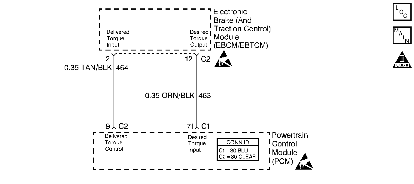
Circuit Description
The traction control system uses the antilock brake system in conjunction with the PCM fuel and ignition controls to limit drive wheel slippage during acceleration. The PCM controlled portion of the traction control system reduces engine torque by any or all of the following methods:
| • | Retarding spark timing |
| • | Altering air/fuel ratio |
| • | Shutting OFF up to three injectors |
To determine the amount of torque reduction required, the PCM monitors the traction control system (TCS) Desired Torque pulse width modulation (PWM) signal from the electronic brake and traction control module (EBCM). The PCM also provides a TCS Delivered Torque PWM informing the EBCM how much torque is being produced by the engine. The Desired Torque display on the scan tool indicates the amount of engine torque requested by the EBCM. With traction control not active, Desired Torque should be approximately 90 percent. The Desired Torque display on the scan tool is not the PWM duty cycle.
Conditions for Running the DTC
The traction control is active.
Conditions for Setting the DTC
| • | The desired torque signal PWM duty cycle is less than 5 percent or more than 95 percent. |
| • | The conditions exists for up to 10 seconds |
Action Taken When the DTC Sets
| • | The PCM does not illuminate the malfunction indicator lamp (MIL). |
| • | The PCM stores the conditions that were present when the DTC set as Fail Records data only. This information will not be stored as Freeze Frame data. |
Conditions for Clearing the MIL/DTC
| • | A history DTC clears after 40 consecutive warm-up cycles have occurred without a malfunction. |
| • | DTC can be cleared by using the scan tool Clear Information function or by disconnecting the PCM battery feed. |
Diagnostic Aids
An intermittent may be caused by a poor connection, rubbed through wire insulation or a broken wire inside the insulation. Check for the following conditions:
| • | A faulty connection or a damaged harness--Inspect the PCM harness for an open or a short to ground in the desired torque PWM circuit, improper mating, broken locks, improperly formed or damaged terminals, poor terminal to wire connection, and a damaged harness. Use a corresponding mating terminal to test for proper terminal tension. |
| • | Intermittent Test |
| Using a scan tool, observe Desired Torque display while moving the related connectors and wiring harnesses. If the failure is induced, the displayed value will change. This may help to isolate the location of the malfunction. |
Reviewing the Fail Records vehicle mileage since the diagnostic test last failed may help determine how often the condition occurs that set the DTC. This may assist in diagnosing the condition.
Step | Action | Values | Yes | No | ||
|---|---|---|---|---|---|---|
1 | Was the Powertrain On-Board Diagnostic (OBD) System Check performed? | -- | ||||
2 |
Is Traction Control Desired Torque at or near the specified value? | 100% | ||||
3 |
Does the voltage measure the specified value? | 5 V | ||||
4 |
Is the frequency between the specified values? | 120-135 Hz | ||||
5 |
Is duty cycle between the specified values? | 5-95% | ||||
6 |
Was a problem found? | -- | ||||
7 |
Was a problem found? | -- | ||||
8 | Replace the EBCM. Refer to Electronic Brake Control Module Replacement . Is the action complete? | -- | -- | |||
9 |
Was a problem found? | -- | ||||
10 |
Important:: The replacement PCM must be programmed. Replace the PCM. Refer to Powertrain Control Module Replacement/Programming Is the action complete? | -- | -- | |||
11 |
Is the Traction Control Desired Torque at or near the specified value? | 100% | System OK |
