Brake Caliper Replacement Front
Removal Procedure
Notice: Use the correct fastener in the correct location. Replacement fasteners must be the correct part number for that application. Fasteners requiring replacement or fasteners requiring the use of thread locking compound or sealant are identified in the service procedure. Do not use paints, lubricants, or corrosion inhibitors on fasteners or fastener joint surfaces unless specified. These coatings affect fastener torque and joint clamping force and may damage the fastener. Use the correct tightening sequence and specifications when installing fasteners in order to avoid damage to parts and systems.
- Remove two-thirds of brake fluid from master cylinder.
- Raise the vehicle and suitably support. Refer to Lifting and Jacking the Vehicle in General Information.
- Remove the wheel and tire assembly. Refer to Tire and Wheel Removal and Installation in Tires and Wheels.
- Compress the caliper piston into caliper bore to allow the piston enough clearance to pass by the bosses on the brake pads.
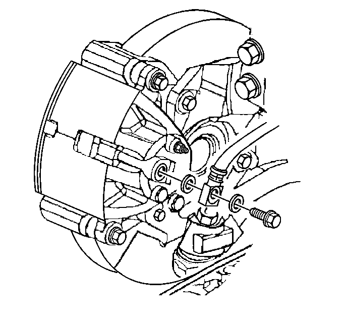
- If the caliper is to be removed for repair, remove the bolt attaching the inlet fitting to the caliper, and plug the opening in the caliper and/or hose to prevent fluid loss and contamination.
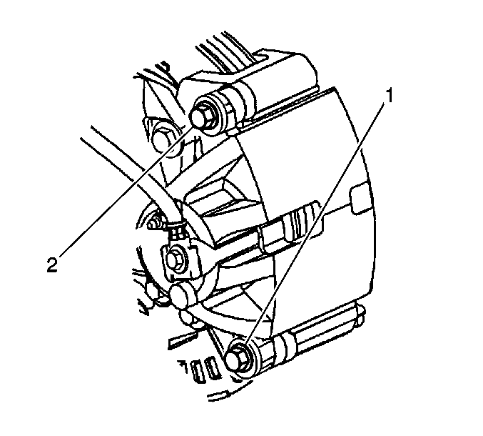
- Remove the caliper pin bolts (1,2).
- Remove the caliper.
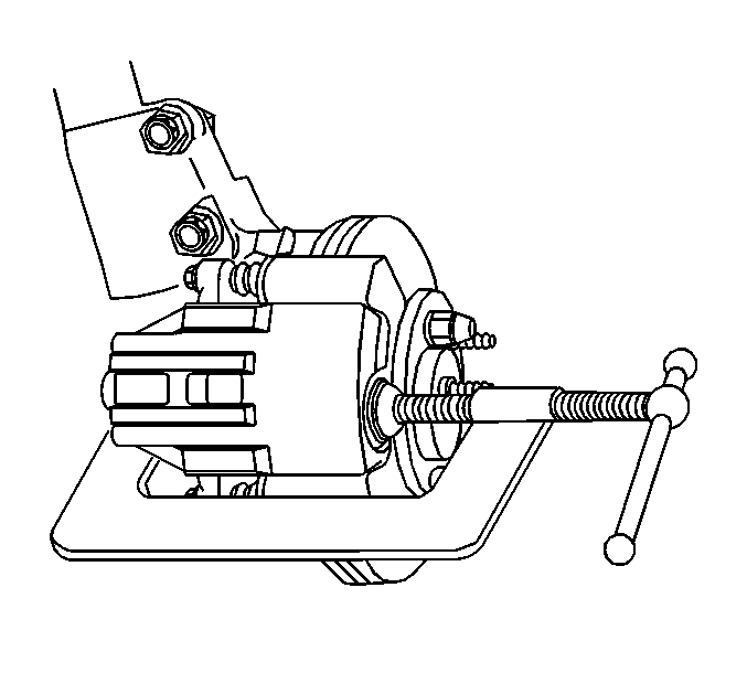
| • | Install a large C-clamp over top of the caliper housing and against back of the outboard pad. |
| • | Slowly tighten C-clamp until piston is pushed into caliper bore far enough to slide caliper off rotor. |
Installation Procedure
- Install the caliper over the brake pads into the caliper anchor bracket.
- Install the caliper pin bolts (1,2).
- Install the brake hose inlet fitting to the caliper.
- Bleed the brake system. Refer to Hydraulic Brake System Bleeding .
- Install the tire and wheel assembly. Refer to Tire and Wheel Removal and Installation in Tires and Wheels.
- Lower the vehicle.
Notice: Use the correct fastener in the correct location. Replacement fasteners must be the correct part number for that application. Fasteners requiring replacement or fasteners requiring the use of thread locking compound or sealant are identified in the service procedure. Do not use paints, lubricants, or corrosion inhibitors on fasteners or fastener joint surfaces unless specified. These coatings affect fastener torque and joint clamping force and may damage the fastener. Use the correct tightening sequence and specifications when installing fasteners in order to avoid damage to parts and systems.

Tighten
Tighten the caliper pin bolts to 85 N·m (63 lb ft).

Tighten
Tighten the brake hose fitting bolt to 45 N·m (33 lb ft).
Brake Caliper Replacement Rear
Removal Procedure
- Remove two-thirds of brake fluid from master cylinder.
- Raise the vehicle and suitably support. Refer to Lifting and Jacking the Vehicle in General Information.
- Remove the wheel and tire assembly. Refer to Tire and Wheel Removal and Installation in Tires and Wheels.
- Using a large C clamp compress the caliper piston into the caliper bore to gain enough clearance to allow the caliper to pivot off the caliper bracket. Compress the piston until resistance is felt, but no more than 1 mm of piston travel.
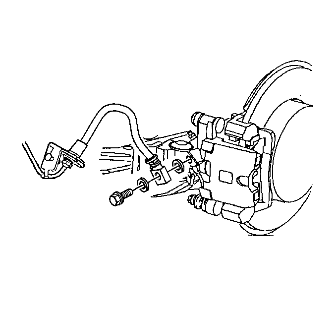
- If the caliper is to be removed for repair, remove the bolt attaching the inlet fitting to the caliper, and plug the opening in the caliper and/or brake hose to prevent fluid loss and contamination.
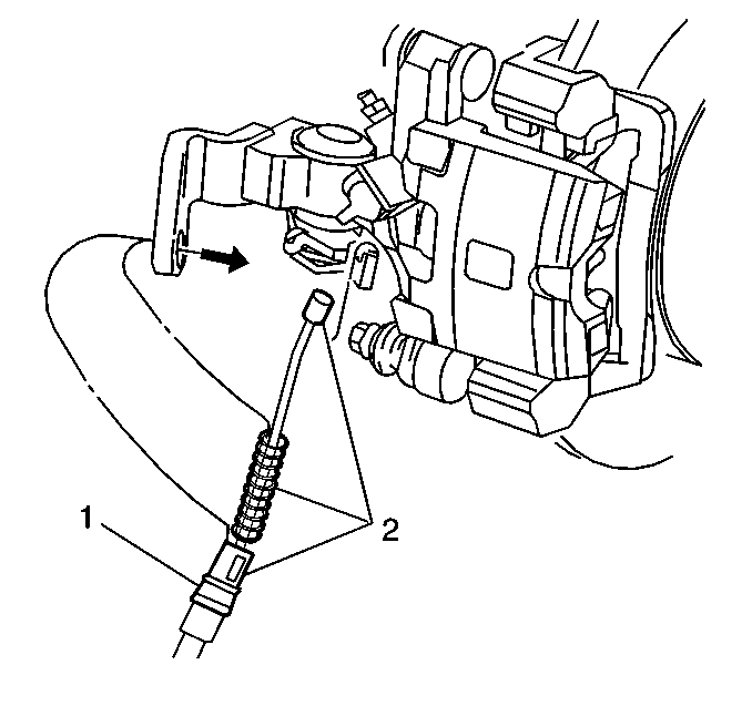
- Remove the park brake cable (1) from the caliper.
- Remove the lower caliper pin bolt.
- Slide the caliper off the upper pin to remove.
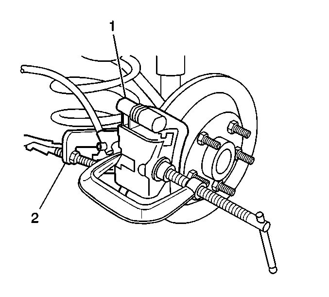
Important: Do not use a screwdriver or pry bar to compress the caliper piston into the caliper. Any damage to the piston boot could cause corrosive elements to enter the piston sealing area and lead to the piston seizing in the caliper bore.
Important: Do not exceed more than 1 mm of piston travel. Damage to the internal adjusting mechanism may result.
Installation Procedure
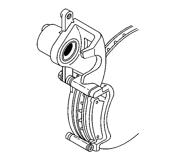
- Install the caliper onto the top caliper slide pin.
- Pivot the caliper (6) down over the brake pads, onto the caliper bracket (5).
- Install the lower caliper pin.
- Install the brake hose inlet fitting to the caliper.
- Install the park brake cable (1) to the caliper.
- Bleed the brake system. Refer to Hydraulic Brake System Bleeding in Hydraulic Brakes.
- Start the vehicle and apply approximately 778 N·m (175 lb. ft.) of force three times to seat the brake caliper piston and the brake pads.
- Recheck the brake fluid. Refer to Master Cylinder Reservoir Filling in Hydraulic Brakes.
- Install the tire and wheel assembly. Refer to Tire and Wheel Removal and Installation in Tires and Wheels.
- Lower the vehicle.
Important: The caliper piston cutouts must be aligned with the locating pins on the brake pad.
Notice: Use the correct fastener in the correct location. Replacement fasteners must be the correct part number for that application. Fasteners requiring replacement or fasteners requiring the use of thread locking compound or sealant are identified in the service procedure. Do not use paints, lubricants, or corrosion inhibitors on fasteners or fastener joint surfaces unless specified. These coatings affect fastener torque and joint clamping force and may damage the fastener. Use the correct tightening sequence and specifications when installing fasteners in order to avoid damage to parts and systems.
Tighten
Tighten the caliper pin to 27 N·m (20 lb ft).

Tighten
Tighten the brake hose fitting bolt to 45 N·m (33 lb ft).

