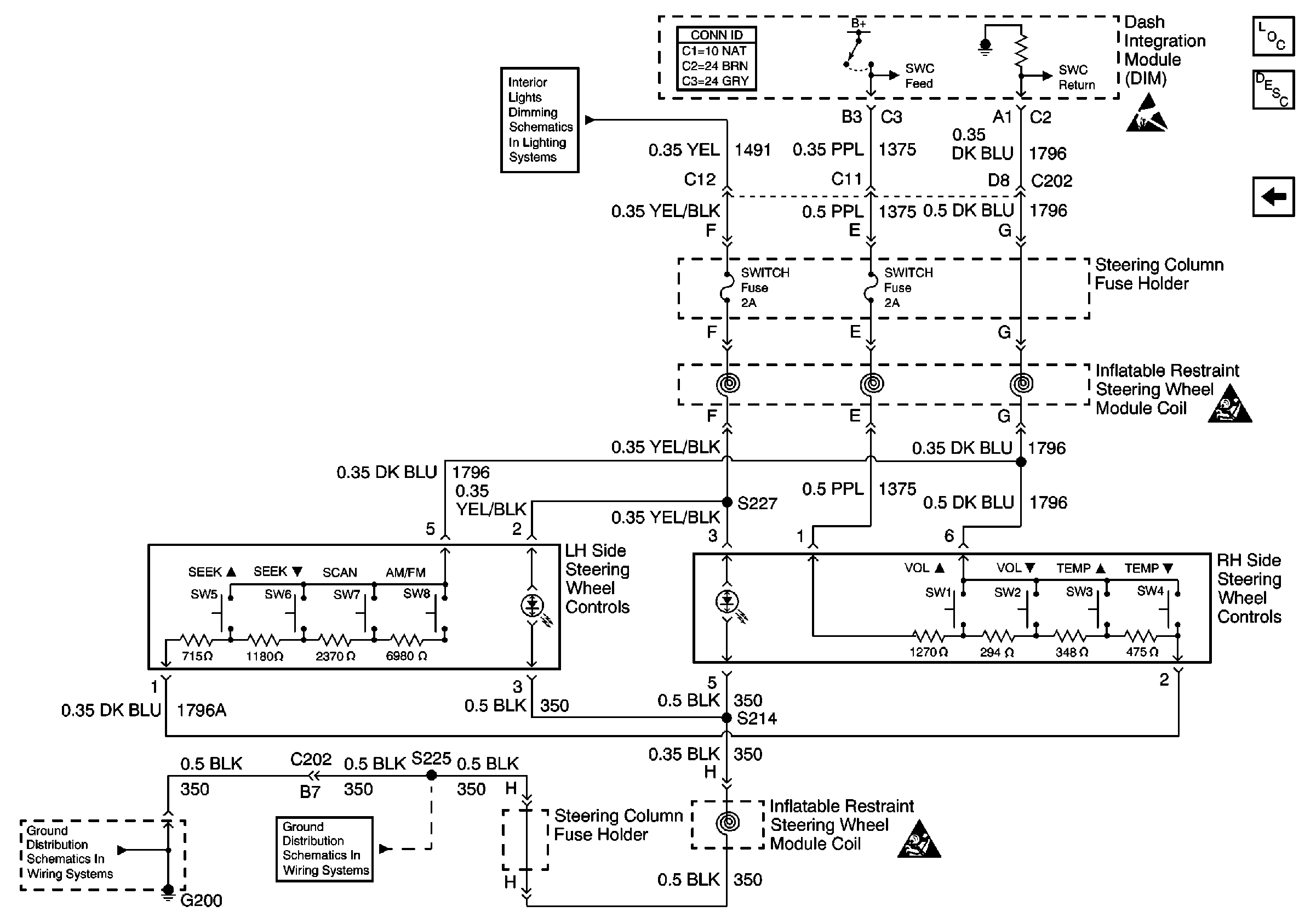
Refer to
Steering Wheel Controls

Step | Action | Value(s) | Yes | No |
|---|---|---|---|---|
1 | Did you perform the HVAC Diagnostic System Check? | -- | Go to Step 2 | Go to Diagnostic System Check |
2 |
Do the counts change for any switch pressed? | -- | Go to Step 3 | Go to Step 5 |
3 |
Do the counts change for all switches pressed? | -- | Go to Step 4 | Go to Step 9 |
4 |
Do the radio steering wheel controls function? | -- | Go to Step 10 | Go to Step 11 |
5 |
Caution: When you are performing service on or near the SIR components or the SIR wiring, you must disable the SIR system. Refer to Disabling the SIR System. Failure to follow the correct procedure could cause air bag deployment, personal injury, or unnecessary SIR system repairs.
Do the counts change? | -- | Go to Step 9 | Go to Step 6 |
6 | Measure the voltage from the SWC feed circuit of the RH side steering wheel controls to a good ground. Does the voltage measure near the specified value? | 12 V | Go to Step 7 | Go to Step 8 |
7 | Test the SWC return circuit of the RH steering wheel controls for an open. Refer to Testing for Intermittent Conditions and Poor Connections and Connector Repairs in Wiring Systems. Did you find and correct the condition? | -- | Go to Step 15 | Go to Step 11 |
8 | Test the SWC feed circuit of the RH steering wheel controls for an open, or a short to ground. Refer to Testing for Intermittent Conditions and Poor Connections and Connector Repairs in Wiring Systems. Did you find and correct the condition? | -- | Go to Step 15 | Go to Step 11 |
9 | Inspect for poor connections at the harness connector of the RH side steering wheel controls. Refer to Testing for Intermittent Conditions and Poor Connections and Connector Repairs in Wiring Systems. Did you find and correct the condition? | -- | Go to Step 15 | Go to Step 12 |
10 | Inspect for poor connections at the harness connector of the Instrument Panel Module (IPM). Refer to Testing for Intermittent Conditions and Poor Connections and Connector Repairs in Wiring Systems. Did you find and correct the condition? | -- | Go to Step 15 | Go to Step 13 |
11 | Inspect for poor connections at the harness connector of the DIM. Refer to Testing for Intermittent Conditions and Poor Connections and Connector Repairs in Wiring Systems. Did you find and correct the condition? | -- | Go to Step 15 | Go to Step 14 |
12 | Replace the RH side steering wheel controls. Refer to Steering Wheel Control Switch Assembly Replacement in Steering Wheel and Column - Tilt. Did you complete the repair? | -- | Go to Step 15 | -- |
13 | Replace the IPM. Refer to Instrument Panel Module Replacement in Body Control System. Did you complete the repair? | -- | Go to Step 15 | -- |
14 | Replace the DIM. Refer to Body Control Module (BCM) Programming/RPO Configuration and Dash Integration Module Replacement in Body Control System. Did you complete the repair? | -- | Go to Step 15 | -- |
15 | Operate the system in order to verify the repair. Did you correct the condition? | -- | System OK | Go to Step 2 |
