Step | Action | Value(s) | Yes | No |
|---|---|---|---|---|
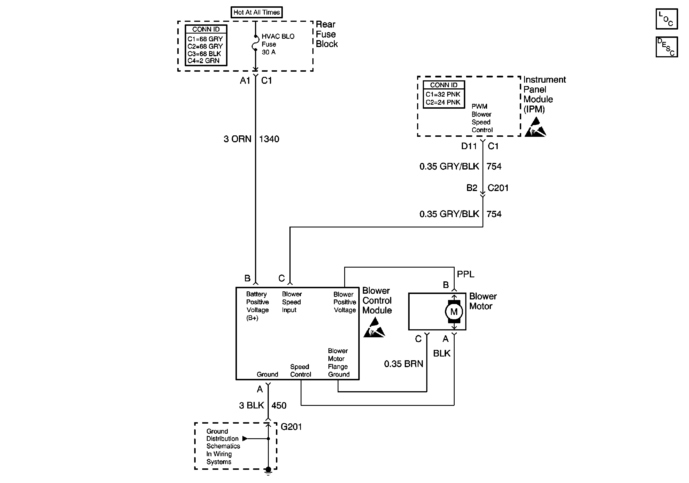
SCHEMATIC
REFERENCE:
| ||||
1 | Did you perform the HVAC Diagnostic System Check? | -- | Go to Step 2 | Go to Diagnostic System Check |
2 |
Does the voltage measure near the specified value? | B+ | Go to Step 3 | Go to Step 9 |
3 | Measure the voltage from the battery positive voltage (B+) circuit of the blower control module to the ground circuit of the blower control module. Does the voltage measure near the specified value? | B+ | Go to Step 4 | Go to Step 10 |
4 |
Does the voltage measure near the specified value? | 5 V | Go to Step 5 | Go to Step 7 |
5 |
Does the voltage measure within the specified value? | 0.25 V to 1.25 V | Go to Step 6 | Go to Step 7 |
6 |
Does the voltage measure within the specified values with a smooth transition between min and max? | 0 V when OFF, 4 to 6 V at min and B+ at max | Go to Step 11 | Go to Step 13 |
7 |
Did you find and correct the condition? | -- | Go to Step 18 | Go to Step 8 |
8 |
Does the voltage measure near the specified value? | 5 V | Go to Step 14 | Go to Step 13 |
9 | Repair the battery positive voltage circuit of the blower control module. Refer to Circuit Testing and Wiring Repairs in Wiring Systems. Did you complete the repair? | -- | Go to Step 18 | -- |
10 | Test the ground circuit of the blower control module for an open. Refer to Circuit Testing and Wiring Repairs in Wiring Systems. Did you find and correct the condition? | -- | Go to Step 18 | -- |
11 | Inspect blower motor for blockage or obstructions preventing free rotation of blower motor wheel. Did you find and correct the condition? | -- | Go to Step 18 | Go to Step 12 |
12 | Inspect for poor connections at the harness connector of the blower motor. Refer to Testing for Intermittent Conditions and Poor Connections and Connector Repairs in Wiring Systems. Did you find and correct the condition? | -- | Go to Step 18 | Go to Step 15 |
13 | Inspect for poor connections at the harness connector of the blower control module. Refer to Testing for Intermittent Conditions and Poor Connections and Connector Repairs in Wiring Systems. Did you find and correct the condition? | -- | Go to Step 18 | Go to Step 16 |
14 | Inspect for poor connections at the harness connector of the instrument panel module. Refer to Testing for Intermittent Conditions and Poor Connections and Connector Repairs in Wiring Systems. Did you find and correct the condition? | -- | Go to Step 18 | Go to Step 17 |
15 | Replace the blower motor. Refer to Blower Motor and Fan Replacement . Did you complete the replacement? | -- | Go to Step 18 | -- |
16 | Replace the blower control module. Refer to Blower Motor Control Module Replacement . Did you complete the replacement? | -- | Go to Step 18 | -- |
17 | Replace the instrument panel module. Refer to Instrument Panel Module Replacement in Body Control System. Did you complete the replacement? | -- | Go to Step 18 | -- |
18 | Operate the system in order to verify the repair. Did you correct the condition? | -- | System OK | Go to Step 2 |

