Removal Procedure
Caution: When you are carrying an undeployed inflator module:
• Do not carry the inflator module by the wires or connector on
the inflator module • Make sure the bag opening points away from you
- Disable the SIR System. Refer to Disabling the SIR System .
- Remove inflatable restraint steering wheel module. Refer to Inflatable Restraint Steering Wheel Module Replacement .
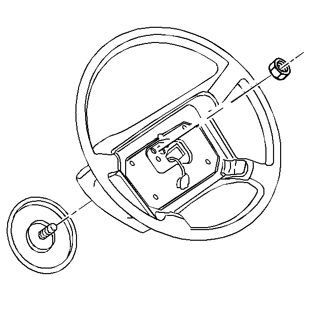
- Remove the steering wheel nut.
- Note the mark on the steering shaft and the steering wheel to ensure proper alignment during installation.
- Remove the steering wheel from the steering shaft. Refer to Steering Wheel Replacement in Steering Wheel and Column -- Tilt.
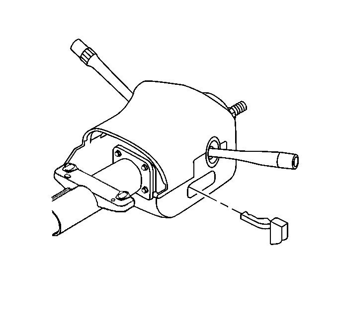
- Grasp the tilt lever.
- Pull the tilt lever straight out from steering column.
- Remove the tilt lever assembly.
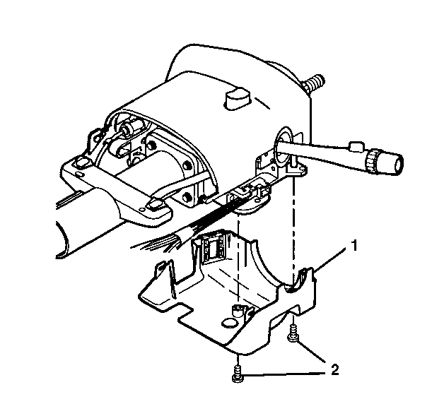
- Remove two pan head tapping screws (2) from the lower shroud (1).
- Remove the lower shroud (1).
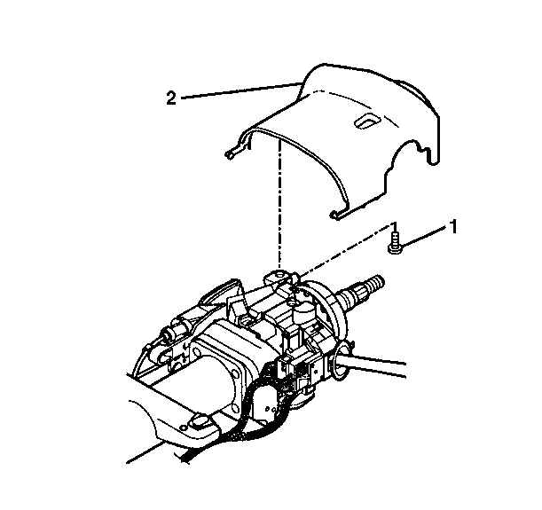
- Remove one TORX® head screw (1) from the upper shroud (2).
- Remove the upper shroud (2).
- Remove the wire harness straps from the steering wheel column wire harness.
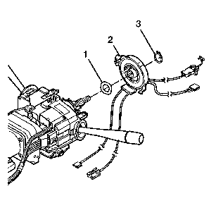
- Remove the retaining ring (3).
- Remove the inflatable restraint steering wheel module coil (2) from the steering shaft.
Installation Procedure
- To install the inflatable restraint steering wheel module coil:
- A new SIR coil assembly will come pre-centered. Ensure that the SIR coil assembly is centered.
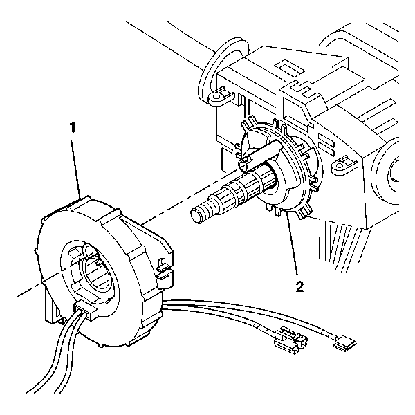
- Align the SIR coil assembly (1) with the horn tower on the turn signal cancel cam assembly (2).
- Install the wave washer (1) to the upper shaft assembly.
- Slide the coil assembly (2) onto the race and upper shaft assembly.
- Remove the centering tab and discard.
- Install the retaining ring (3).
- Install the upper shroud (2) and secure by using one TORX® head screw (1).
- Install the lower shroud (2) and secure by using two pan head tapping screws (1).
- Align the tilt lever into the steering column.
- Slide the tilt lever handle into the steering column until it locks into position.
- Feed the wiring through the steering wheel.
- Align the steering wheel with the mark on the steering shaft.
- Install the nut for the steering wheel.
- Connect the wiring to the SIR module.
- Install the inflatable restraint steering wheel module. Refer to Inflatable Restraint Steering Wheel Module Replacement .
- Enable the SIR system. Refer to Enabling the SIR System .
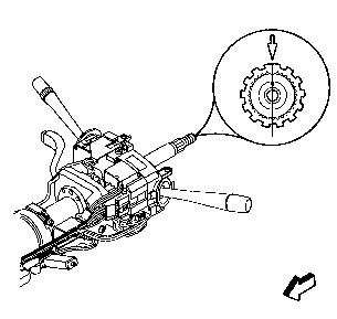
| • | Ensure that the wheels are straight ahead. |
| • | Align the block tooth and the centering mark on the race and upper shaft assembly (1) at the 12 o'clock position. |
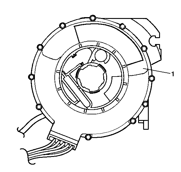
Important: If coil assembly centering is required follow the instructions on the notice (1) of the coil assembly. Refer to Inflatable Restraint Coil Centering - Off Vehicle for complete centering procedure in Steering.


Notice: Use the correct fastener in the correct location. Replacement fasteners must be the correct part number for that application. Fasteners requiring replacement or fasteners requiring the use of thread locking compound or sealant are identified in the service procedure. Do not use paints, lubricants, or corrosion inhibitors on fasteners or fastener joint surfaces unless specified. These coatings affect fastener torque and joint clamping force and may damage the fastener. Use the correct tightening sequence and specifications when installing fasteners in order to avoid damage to parts and systems.
Tighten
Tighten the screw to 1.5 N·m (13 lb in).

Tighten
Tighten the screws to 3.5 N·m (31 lb in).


Tighten
Tighten the nut to 41 N·m (30 lb ft).
