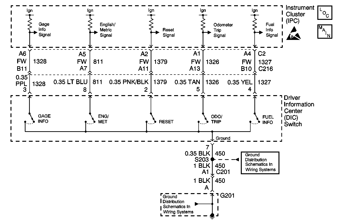
Circuit Description
The instrument panel cluster (IPC) contains switch circuits that allow certain functions to be performed when depressed. The IPC monitors these circuit voltage levels and detects when a certain button has been depressed by the voltage drop. If the voltage is not within range for a pre-determined amount of time, the IPC detects the malfunction and sets a DTC.
Conditions for Running the DTC
The IPC and the gauge info switch must be active.
Conditions for Setting the DTC
The IPC detects the gauge info switch input low (shorted to ground) for 15 continuous seconds.
Action Taken When the DTC Sets
The IPC disables (ignores) the gauge info switch input therefore the correct status of the switch will not be known when requested through the DLC.
Conditions for Clearing the DTC
The IPC does not detect a failure for 2 passes through the self diagnostic mode.
Diagnostic Aids
The IPC will store the code as current only as long as the failure exists. An intermittent failure will be stored as a history DTC.
Test Description
The numbers below refer to the step numbers on the diagnostic table.
Step | Action | Value(s) | Yes | No |
|---|---|---|---|---|
1 | Did you perform the Instrument Cluster Diagnostic System Check? | -- | Go to Step 2 | |
2 |
Does the scan tool display Off? | -- | Go to Step 3 | Go to Step 4 |
3 |
Does the Display Gauge Switch parameter change state? | -- | Go to Testing for Intermittent Conditions and Poor Connections in Wiring Systems | Go to Step 4 |
Does the scan tool display Off? | -- | Go to Step 7 | Go to Step 5 | |
5 |
Notice: The circuit terminates at a flat wire connector. Use the J 42675 Flat Wire Probe Adapter Kit in order to avoid damage and properly test the circuit. Test the signal circuit of the GAGE INFO switch for a short to ground. Refer to Circuit Testing and Wiring Repairs in Wiring Systems. Did you find and correct the condition? | -- | Go to Step 10 | Go to Step 6 |
6 | Inspect for poor connections at the harness connector of the IPC. Refer to Testing for Intermittent Conditions and Poor Connections and Connector Repairs in Wiring Systems. Did you find and correct the condition? | -- | Go to Step 10 | Go to Step 8 |
7 | Inspect for poor connections at the harness connector of the DIC switch. Refer to Testing for Intermittent Conditions and Poor Connections and Connector Repairs in Wiring Systems. Did you find and correct the condition? | -- | Go to Step 10 | Go to Step 9 |
8 | Replace the IPC. Refer to Instrument Cluster Replacement . Did you complete the replacement? | -- | Go to Step 10 | -- |
9 | Replace the DIC switch. Refer to Driver Information Display Switch Replacement . Did you complete the replacement? | -- | Go to Step 10 | -- |
10 |
Does the DTC reset? | -- | Go to Step 2 | System OK |
