Product Safety 00035 - Antilock Brake System Internal Brake Fluid Leak

| Subject: | 00036 -- Antilock Brake System Internal Brake Fluid Leak |
| Models: | Certain 2000 Buick LeSabre/Park Avenue; Pontiac Bonneville; Cadillac Seville; DeVille; Oldsmobile Intrigue and 2001 Oldsmobile Aurora Model Vehicles |
Condition
General Motors has decided that a defect which relates to motor vehicle safety exists in certain 2000 Buick LeSabre, Buick Park Avenue, Pontiac Bonneville, Cadillac Seville, Cadillac DeVille, Oldsmobile Intrigue and 2001 Oldsmobile Aurora model vehicles equipped with antilock brakes. Some of these vehicles have internal fluid leaks in the antilock brake system's hydraulic control unit. Functions performed by that unit, rear brake proportioning, antilock brake, traction control (if equipped), and stability control (if equipped), may not perform as designed. The driver could lose control and a crash could occur without prior warning. Other hydraulic brake system functions are not affected.
Correction
Dealers are to inspect the ABS brake pressure modulator valve/electronic brake control module assembly and if necessary, replace the hydraulic modulator or hydraulic modulator/electronic brake control module assembly.
Important: IF INSPECTION AND TEST INDICATE THAT THE BRAKE PRESSURE MODULATOR VALVE REQUIRES REPLACEMENT, DEALER SHOULD HOLD THE INVOLVED VEHICLES UNTIL PARTS CAN BE OBTAINED AND REPAIRS PERFORMED. OWNERS OF VEHICLES REQUIRING REPLACEMENT OF THE BRAKE PRESSURE MODULATOR VALVE SHOULD BE PROVIDED WITH ALTERNATE TRANSPORTATION AS REQUIRED.
Important: PARTS REPLACED UNDER THIS PRODUCT SAFETY CAMPAIGN WILL BE REQUESTED
FOR RETURN BY THE WARRANTY PARTS CENTER (WPC) IN ACCORDANCE WITH WARRANTY
ADMINISTRATION BULLETIN #99-00-89-019, DATED OCTOBER, 1999.
DO NOT RETURN PARTS WITHOUT THE WPC REQUEST PAPERWORK.
• DEALERS ARE ENCOURAGED TO PROCESS THEIR WARRANTY CLAIMS AS QUICKLY
AS POSSIBLE IN ORDER TO EXPEDITE THE RETURN REQUESTS FROM THE WPC. DEALERS
WILL RECEIVE A WPC REQUEST WHEN THE CLAIM IS PAID. • PLEASE PACKAGE THE PART IN THE REPLACEMENT GMSPO PART CONTAINER,
ALONG WITH A COPY OF THE WPC REQUEST AND THE REPAIR ORDER. RETURN THE PART
IMMEDIATELY UPON RECEIPT OF THE WPC RETURN REQUEST, USING THE WPC PRE-PRINTED
UPS/ARS LABELS PREVIOUSLY PROVIDED. • DO NOT INCLUDE OTHER UNRELATED PARTS WITH THIS SHIPMENT TO THE
WPC.
Vehicles Involved
Involved are certain 2000 Buick LeSabre, Buick Park Avenue, Pontiac Bonneville, Cadillac Seville, Cadillac DeVille, Oldsmobile Intrigue, and 2001 Oldsmobile Aurora model vehicles equipped with antilock brakes (RPOs JE1, JL4, JL9, NW9, and certain combinations of these RPOs) and built within these VIN breakpoints:
Year | Division | Model | Plant | From | Through |
|---|---|---|---|---|---|
2000 | Cadillac | DeVille | Hamtramck | YU235314 | YU245843 |
2000 | Cadillac | Seville | Hamtramck | YU237366 | YU245838 |
2000 | Buick | LeSabre | Hamtramck | YU234939 | YU245842 |
2000 | Buick | LeSabre | Orion | Y4203390 | Y4210756 |
2000 | Buick | Park Avenue | Orion | Y4206273 | Y4210754 |
2000 | Pontiac | Bonneville | Orion | Y4202182 | Y4210755 |
2000 | Oldsmobile | Intrigue | Fairfax | YF246349 | YF253910 |
2001 | Oldsmobile | Aurora | Orion | 14101724 | 14103037 |
Important: Dealers should confirm vehicle eligibility through GMVIS (GM Vehicle Inquiry System) or GM Access Screen (Canada only) or DCS Screen 445 (IPC Only) before beginning campaign repairs. [Not all vehicles within the above breakpoints may be involved.]
Involved vehicles have been identified by Vehicle Identification Number. Computer listings containing the complete Vehicle Identification Number, customer name and address data have been prepared, and are being furnished to involved dealers with the campaign bulletin. The customer name and address data furnished will enable dealers to follow-up with customers involved in this campaign. Any dealer not receiving a computer listing with the campaign bulletin has no involved vehicles currently assigned.
These dealer listings may contain customer names and addresses obtained from Motor Vehicle Registration Records. The use of such motor vehicle registration data for any other purpose is a violation of law in several states/provinces/countries. Accordingly, you are urged to limit the use of this listing to the follow-up necessary to complete this campaign.
Parts Information
Parts required to complete this campaign are to be obtained from General Motors Service Parts Operations (GMSPO). Please refer to your "involved vehicles listing" before ordering parts. Normal orders should be placed on a DRO = Daily Replenishment Order. In an emergency situation, parts should be ordered on a CSO = Customer Special Order.
Part Number | Description | Qty/ Vehicle |
|---|---|---|
10443971 | Valve, Brk Press Mod (w/Elek Brk & Tract Cont Mdl) | 0 or 1 |
25698056 | Valve, Brk Press Mod | 0 or 1 |
25698057 | Valve, Brk Press Mod | 0 or 1 |
25698058 | Valve, Brk Press Mod | 0 or 1 |
Important: Due to the small number of vehicles involved and due to extremely limited initial parts availability, dealers are encouraged not to order campaign pars for use as shelf stock. Parts should only be ordered when inspection determines that it is necessary to replace the antilock brake system hydraulic modulator.
Service Procedure -- Inspection
Important: Updated calibration data required for this service procedure is available on CD#9 (software version no. 20-004), released May 10, 2000 (released May 6, 2000 to Canadian dealers; released May 25, 2000 to IPC dealers).
The Tech 2 test(s) in this service procedure require two technicians. The Tech 2 test for the Intrigue has two (2) parts. The first part tests the inlet valves. The second part tests the isolation valves. The Tech 2 test for the Aurora, Bonneville, DeVille, LeSabre, Park Avenue, and Seville has only one part and tests the inlet valves only.- Locate the brake pressure modulator valve serial number stamping as shown in Figure 1. The serial number stamping has forward slashes (/) in it.
- Clean the serial number stamping as necessary for clear viewing of the stamping.
- Check the first three characters (year and month of build) of the brake pressure modulator valve serial number stamping.
- Check the fourth and fifth characters (day of month) of the brake pressure modulator valve serial number stamping.
- Check the sixth character (manufacturing line no.) of the brake pressure modulator valve serial number stamping.
Figure 1
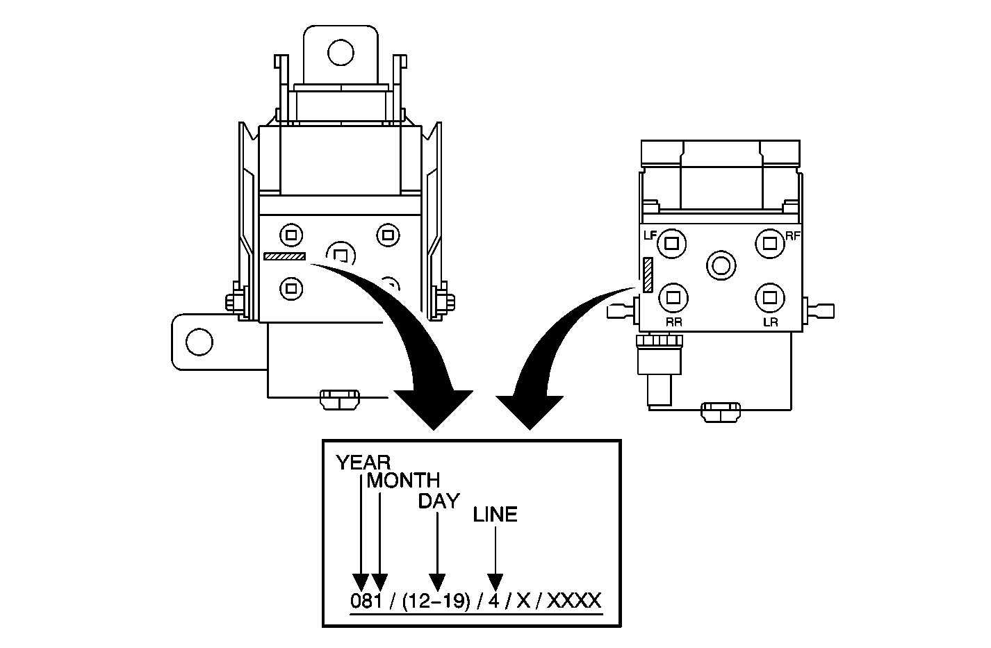
| • | If the first three characters of the stamping ARE 081, proceed to Step 4. |
| • | If the first three characters are NOT 081, proceed to the last step of this service procedure (install campaign identification label). |
| • | If the characters ARE 12, 13, 14, 15, 16, 17, 18 or 19, proceed to Step 5. |
| • | If the characters are NOT 12, 13, 14, 15, 16, 17, 18 or 19, proceed to the last step of this service procedure (install campaign identification label). |
| • | If the character IS "4" and the vehicle is an Intrigue, proceed to Step 6. |
| • | If the character IS "4" and the vehicle is an Aurora, Bonneville, DeVille, LeSabre, Park Avenue, or Seville, proceed to Tech 2 Brake Pressure Modulator Valve Test Procedure-Inlet Valves Only (Aurora, Bonneville, DeVille, LeSabre, Park Avenue, Seville). |
| • | If the character is NOT "4", proceed to the last step of this service procedure (install campaign identification label). |
Tech 2 Brake Pressure Modulator Valve Test Procedure-Inlet Valves (Intrigue)
- Position the vehicle on a hoist with one technician in the vehicle. Raise and suitably support the vehicle.
- Install the Tech 2 to the Data Link Connector (DLC).
- Press the "Power" button on the Tech 2.
- When the "Main Menu" screen appear, press "Enter."
- Select "Diagnostics" and press "Enter."
- Select "Model Year" and press "Enter."
- Select "Passenger Car" and press "Enter."
- Select "Chassis" and press "Enter."
- Select body style "W" and press "Enter."
- Select "(3) Oldsmobile" and press "Enter."
- At the "Chassis Menu," select "Special Functions" and press "Enter."
- At the "Special Functions Menu," select "Solenoid Test" and press "Enter."
- Select "LF Inlet Valve Solenoid" and press "Enter."
- With the ignition ON (engine not running), shift the vehicle to Neutral and make sure than the park brake is NOT applied. The technician outside of the vehicle should verify that the wheels are free-spinning before the start of the test sequence by rotating the wheels by hand.
- Turn the selected inlet valve ON with the Tech 2
- Being SLOWLY spinning the corresponding selected wheel by hand.
- Apply the service brake (medium to heavy brake pedal force) and hold for a maximum of 20 seconds.
Important: Rotate the wheel at one revolution per second or slower.
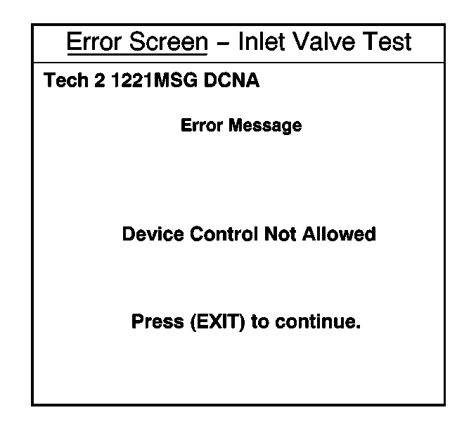
| • | If the wheel under test locks up (stops spinning) while the technician is trying to turn the wheel by hand, AND an error message is displayed on the Tech 2 stating "Device Control Not Allowed" (refer to illustration), abort the test. The wheel is being turned too fast. Return to Step 14 and repeat the test, turning the wheel slower. |
| • | If the wheel under test locks up (stops spinning) while the technician is trying to turn the wheel by hand, and there is no error message, the brake pressure modulator valve/electronic brake control module has a damaged seal and should be replaced following the instructions in the appropriate section of this service procedure. |
| • | If the wheel under test continues to spin freely, turn the inlet valve OFF with the Tech 2 and return to Step 13 and repeat the test until all four locations (LF, RF, LR, RR) have been tested, or until a wheel locks up/stops spinning during the test. |
| • | If all four locations test OK (wheels do not lock up or stop spinning during the test), proceed to the Tech 2 Brake Pressure Modulator Valve Test Procedure-Isolation Valve (Intrigue). |
Tech 2 Brake Pressure Modulator Valve Test Procedure-Isolation Valve (Intrigue)
- Return to the "Main Menu" screen and press the "Power" key to turn OFF the Tech 2.
- Place the transaxle in Park and start the engine.
- Press the "Power" button on the Tech 2.
- When the "Main Menu" screen appears, press "Enter."
- Select "Diagnostics" and press "Enter."
- Select "Model Year" and press "Enter."
- Select "Passenger Car" and press "Enter."
- Select "Chassis" and press "Enter."
- Select the body style (W) and press "Enter."
- Select "(3) Oldsmobile" and press "Enter."
- At the "Chassis Menu" select "Special Functions" and press "Enter."
- At the "Special Functions Menu" select "Isolation Valve Test" and press "Enter."
- Follow the directions on the Tech 2 screen.
- Increase and maintain engine speed between 1200-1800 RPM (displayed on Tech 2) with your foot on the brake pedal.
- Once the engine speed is increased to 1200 RPM, the "Tech 2 ISOVALVE RELBRK" screen will be automatically displayed. If 1200 RPM is not reached within a specified period of time, the test will be automatically aborted.
- Maintain 1200-1800 RPM for approximately 10 seconds. The time remaining in the test is displayed on seconds on the Tech 2 screen until screen 5 is displayed.
- At the end of the test, Screen 5 is displayed.
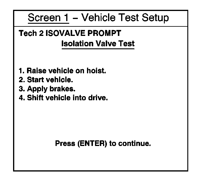
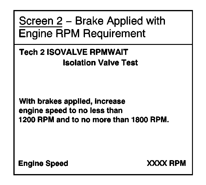
Important: The following step requires one foot on the brake pedal and the other foot on the accelerator pedal.
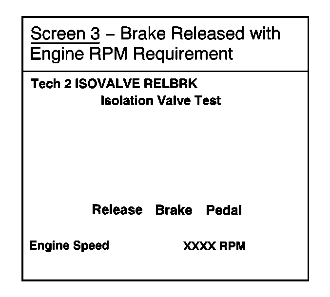
Important: While maintaining 1200-1800 RPM (displayed on the Tech 2), release the brake pedal when this screen is displayed. If the brake pedal is not released within a specified period of time, the test will be automatically aborted.
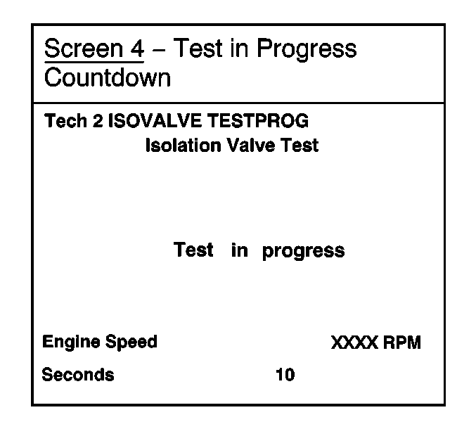
Important: During this countdown, the second technician must visually monitor the front wheels to observe if one or both of the wheels begin to spin.
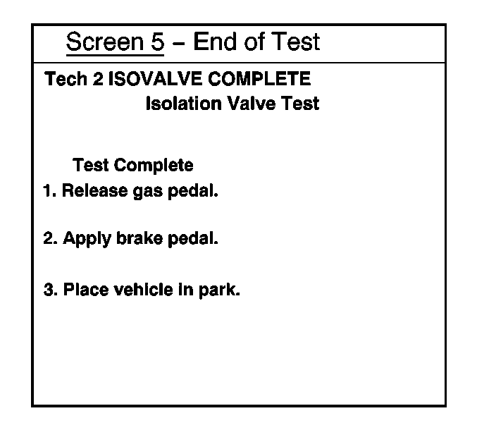
| • | If one or both of the front wheels rotated more than one (1) revolution during the ten second test sequence, the brake pressure modulator valve unit has a damaged seal and the complete brake pressure modulator valve/electronic brake control module should be replaced following the instructions in the appropriate section of this service procedure. |
| • | If neither of the front wheels rotated more than one (1) revolution during the ten second test sequence, the brake pressure modulator valve is OK. Proceed to the last step of the service procedure and install the campaign identification label. |
Tech 2 Brake Pressure Modulator Valve Test Procedure-Inlet Valve Only (Aurora, Bonneville, DeVille, LeSabre, Park Avenue, Seville)
- Position the vehicle on a hoist with one technician in the vehicle. Raise and suitably support the vehicle.
- Install the Tech 2 to the Data Link Connector (DLC).
- Press the "Power" button on the Tech 2.
- When the "Main Menu" screen appear, press "Enter."
- Select "Diagnostics" and press "Enter."
- Select "Model Year" and press "Enter."
- Select "Passenger Car" and press "Enter."
- Select "Chassis" and press "Enter."
- Select the appropriate body style and press "Enter."
- Select the appropriate carline series (if applicable) and press "Enter."
- At the "Chassis Menu," select "DRP/ABS/..." and press "Enter."
- At the "Special Functions Menu," select "Solenoid Test" and press "Enter."
- Select "LF Inlet Valve Solenoid" and press "Enter."
- With the ignition ON (engine not running), shift the vehicle to Neutral and make sure than the park brake is NOT applied. The technician outside of the vehicle should verify that the wheels are free-spinning before the start of the test sequence by rotating the wheels by hand.
- Turn the selected inlet valve ON with the Tech 2.
- Begin SLOWLY spinning the selected wheel by hand.
- Apply the service brake (medium to heavy brake pedal force) and hold for a maximum of 20 seconds.
| • | "C" for Buick Park Avenue |
| • | "G" for Oldsmobile Aurora |
| • | "H" for Buick LeSabre |
| • | "H" for Pontiac Bonneville |
| • | "K" for Cadillac DeVille or Seville |

| • | If the wheel under test locks up (stops spinning) while the technician is trying to turn the wheel by hand, AND an error message is displayed on the Tech 2 stating "Device Control Not Allowed" (refer to illustration), abort the test. The wheel is being turned too fast. Return to Step 14 and repeat the test, turning the wheel slower. |
| • | If the wheel under test locks up (stops spinning) while the technician is trying to turn the wheel by hand, and there is no error message, the brake pressure modulator valve/electronic brake control module has a damaged seal and should be replaced following the instructions in the appropriate section of this service procedure. |
| • | If the wheel under test continues to spin freely, turn the inlet valve OFF with the Tech 2 and return to Step 13 and repeat the test until all four locations (LF, RF, LR, RR) have been tested, or until a wheel locks up/stops spinning during the test. |
| • | If all four locations test OK (wheels do not lock up or stop spinning during the test), the brake pressure modulator is OK. Proceed to the last step of this service procedure and install the campaign identification label. |
Service Procedure -- Replacement of Brake Pressure Modulator Valve/Electronic Brake Control Module
Replacement of Brake Pressure Modulator Valve/Electronic Brake Control Module (Intrigue)
- Disconnect the negative battery cable.
- Remove the nuts securing the cruise control servo mounting bracket to the strut tower and relocate the unit in order to gain access to the electronic brake control module (EBCM)/brake pressure modulator valve (BPMV) assembly.
- Disconnect the EBCM harness electrical and the BPMV pressure sensor connectors.
- Disconnect the two master cylinder brake pipes from the BPMV.
- Disconnect the four wheel brake pipes from the BPMV.
- Remove the two EBCM/BPMV assembly-to-mounting bracket nuts and remove the assembly from the vehicle.
- Install the new EBCM/BPMV assembly into the mounting bracket. Make sure that the assembly is firmly seated onto the bottom bracket pin. Secure the assembly in position with the mounting bracket nuts.
- Connect the wheel brake pipes and the master cylinder brake pipes to the correct ports on the BPMV as noted when they were disconnected.
- Connect the EBCM harness electrical and the BPMV pressure sensor connector.
- Clean the EBCM/BPMV assembly and the surrounding area of any brake fluid.
- Position the cruise control servo mounting bracket.
- Proceed to Replacement of Brake Pressure Modulator Valve/Electronic Brake Control Module (All).
Important: To ensure that the pipe fittings are reconnected to the proper ports on the BPMV, note their location prior to disconnecting them.
Tighten
Tighten the mounting bracket nuts to 10 N·m (89 lb in).
Tighten
Tighten all six of the brake pipe fittings to 15 N·m (11 lb ft).
Tighten
Tighten the mounting nuts to 2 N·m (18 lb in).
Replacement of Brake Pressure Modulator Valve/Electronic Brake Control Module (LeSabre/Park Avenue/Bonneville)
- Disconnect the negative battery cable.
- Disconnect the EBCM harness electrical connector.
- Disconnect the two master cylinder brake pipes from the BPMV.
- Disconnect the four wheel brake pipes from the BPMV.
- Remove the two BPMV-to-mounting bracket nuts. Remove the EBCM/BPMV assembly from the vehicle.
- Disconnect the BPMV 2-pin electrical connector from the EBCM.
- Remove the six EBCM-to-BPMV mounting screws. Separate the components.
- Clean the EBCM sealing surface of any brake fluid or contamination.
- Position the EBCM to the new BPMV. Hand start the six mounting screws.
- Connect the BPMV 2-pin electrical connector to the EBCM.
- Install the EBCM/BPMV assembly into the mounting bracket. Make sure that the assembly is firmly seated onto the bottom bracket pin. Secure the assembly in position by installing the mounting bracket nuts.
- Connect the wheel brake pipes and the master cylinder brake pipes to the correct ports on the BPMV as noted when they were disconnected.
- Connect the EBCM electrical connector.
- Clean the BPMV assembly and the surrounding area of any brake fluid.
- Proceed to Replacement of Brake Pressure Modulator Valve/Electronic Brake Control Module (All).
Important: To ensure that the pipe fittings are reconnected to the proper ports on the BPMV, note their location prior to disconnecting them.
Tighten
Tighten the mounting screws to 3.2 N·m (28 lb in).
Tighten
Tighten the mounting bracket nuts to 10 N·m
(89 lb in).
Tighten
Tighten all six of the brake pipe fittings to 15 N·m (11 lb ft).
Replacement of Brake Pressure Modulator Valve (DeVille/Seville)
- Disconnect the negative battery cable.
- Raise and suitably support the vehicle.
- Remove the front lower air deflector.
- Disconnect the EBCM harness electrical connector.
- Disconnect the two master cylinder brake pipes from the BPMV.
- Disconnect the four wheel brake pipes from the BPMV.
- Remove the two BPMV-to-mounting bracket nuts. Remove the EBCM/BPMV assembly from the vehicle.
- Disconnect the BPMV 2-pin electrical connector from the EBCM.
- Remove the six EBCM-to-BPMV mounting screws. Separate the components.
- Clean the EBCM sealing surface of any brake fluid or contamination.
- Position the EBCM to the new BPMV. Hand start the six mounting screws.
- Connect the BPMV 2-pin electrical connector to the EBCM.
- Install the EBCM/BPMV assembly into the mounting bracket. Make sure that the assembly is firmly seated onto the bottom bracket pin. Secure in position by installing the mounting bracket nuts.
- Connect the wheel brake pipes and the master cylinder brake pipes to the correct ports on the BPMV as noted when they were disconnected.
- Connect the EBCM harness electrical connector.
- Clean the EBCM/BPMV assembly and the surrounding area of any brake fluid.
- Install the front lower air deflector.
- Lower the vehicle.
- Proceed to Replacement of Brake Pressure Modulator Valve/Electronic Brake Control Module (All).
Important: To ensure that the pipe fittings are reconnected to the proper ports on the BPMV, note their location prior to disconnecting them.
Tighten
Tighten the mounting screws to 3.2 N·m (28 lb in).
Tighten
Tighten the mounting bracket nuts to 10 N·m (89 lb in).
Tighten
Tighten all six of the brake pipe fittings to 15 N·m (11 lb ft).
Replacement of Brake Pressure Modulator Valve (Aurora)
- Disconnect the negative battery cable.
- Remove the air cleaner assembly in order to gain access to the EBCM/BPMV assembly. Refer to the Air Cleaner Replacement procedure in the Service Manual.
- Disconnect the EBCM harness electrical connector.
- Disconnect the two master cylinder brake pipes from the BPMV.
- Disconnect the four wheel brake pipes from the BPMV.
- Remove the two BPMV-to-mounting bracket nuts. Remove the EBCM/BPMV assembly from the vehicle.
- Disconnect the BPMV 2-pin electrical connector from the EBCM.
- Remove the six EBCM-to-BPMV mounting screws. Separate the components.
- Clean the EBCM sealing surface of any brake fluid or contamination.
- Position the EBCM to the new BPMV. Hand start the six mounting screws.
- Connect the BPMV 2-pin electrical connector to the EBCM.
- Install the EBCM/BPMV assembly into the mounting bracket. Make sure that the assembly is firmly seated onto the bottom bracket pin. Secure in position by installing the mounting bracket nuts.
- Connect the wheel brake pipes and the master cylinder brake pipes to the correct ports on the BPMV as noted when they were disconnected.
- Connect the EBCM harness electrical connector.
- Clean the EBCM/BPMV assembly and the surrounding area of any brake fluid.
- Install the air cleaner assembly. Refer to the Air Cleaner Replacement procedure in the Service Manual.
- Proceed to Replacement of Brake Pressure Modulator Valve/Electronic Brake Control Module (All).
Important: To ensure that the pipe fittings are reconnected to the proper ports on the BPMV, note their location prior to disconnecting them.
Tighten
Tighten the mounting screws to 3.2 N·m (28 lb in).
Tighten
Tighten the mounting bracket nuts to 10 N·m (89 lb in).
Tighten
Tighten all six of the brake pipe fittings to 15 N·m (11 lb ft).
Replacement of Brake Pressure Modulator Valve/Electronic Brake Control Module (All)
- Connect the negative battery cable.
- If the vehicle is an Aurora, Bonneville, LeSabre or Park Avenue AND is equipped with the Tire Inflation Monitor System (TIMS):
- Fill and bleed the hydraulic brake system. Refer to Master Cylinder Reservoir Filling and Hydraulic Brake System Bleeding in the Hydraulic Brake section of the appropriate Service Manual.
- Perform the Auto Bleed Procedure. Refer to Automated Bleed Procedure in the appropriate Service Manual.
- Perform the ABS Diagnostic System Check. Refer to Diagnostic System Check-ABS in the appropriate Service Manual.
- Install the GM Campaign Identification Label.
| 2.1. | Reset the TIMS (Tire Pressure Reset) using the Tech 2. |
| 2.2. | Clear ABS codes using the Tech 2. |
Campaign Identification Label
FOR US AND IPC
Place a Campaign Identification Label on each vehicle corrected in accordance with the instructions outlined in this Product Campaign Bulletin. Each label provides a space to include the campaign number and the five (5) digit dealer code of the dealer performing the campaign service. This information may be inserted with a typewriter or a ball point pen.
Put the Campaign Identification Label on a clean and dry surface of the radiator core support in an area that will be visible to people servicing the vehicle. When installing the Campaign Identification Label, be sure to pull the tab to allow the adhesion of the clear protective covering. Additional Campaign Identification Labels for US dealers can be obtained from Dealer Support Material by calling 1-888-549-6152 (Monday-Friday, 8:00 am to 5:00 pm EST). Ask for Item Number S-1015 when ordering.
Additional Campaign Identification Labels for IPC dealers can be obtained from your Regional Marketing Office.
Campaign Identification Label
FOR CANADA
Place a Campaign Identification Label on each vehicle corrected in accordance with the instructions outlined in this Product Campaign Bulletin. Each label provides a space to include the campaign number and the five (5) digit dealer code of the dealer performing the campaign service. This information may be inserted with a typewriter or a ball point pen.
Put the Campaign Identification Label on a clean and dry surface of the radiator core support in an area that will be visible to people servicing the vehicle. Additional Campaign Identification Labels for Canadian dealers can be obtained from DGN by calling 1-800-668-5539 (Monday-Friday, 8:00 am to 5:00 pm EST). Ask for Item Number GMP 91 when ordering.
Claim Information
Submit a Product Campaign Claim with the information indicated below:
Repair Performed | Part Count | Part No. | Parts Allow | CC-FC | Labor Op | Labor Hours* | Net Item |
|---|---|---|---|---|---|---|---|
Visual Inspect Only | -- | NA | -- | MA-96 | V0530 | *0.2 | -- |
Add: Perform Tech 2 Test (Include time for 2nd technician) | 0.1 | ||||||
Inspect and Replace Hydraulic Unit | 1 | 10443971 | ** | MA-96 | V0531 | * | *** |
Intrigue | 1.2 | ||||||
LeSabre/Park Avenue/Bonneville | 1.3 | ||||||
Seville/DeVille/Aurora | 1.5 | ||||||
Courtesy transportation (sold retail vehicles only) | -- | -- | -- | MA-96 | V0532 | -- | **** |
* -- For Campaign Administrative Allowance, add 0.1 hours to the "Labor Hours". ** -- The "Parts Allowance" should be the sum total of the current GMSPO Dealer Net price plus applicable Mark-Up or Landed Cost Mark-Up (for IPC) for Brake Pressure Modulator Valve or Brake Pressure Modulator Valve with Electronic Brake Control Module needed to complete the repair. *** -- The amount identified in the "Net Item" column should represent the sum total of the Current GMSPO Net Price plus applicable Mark-Up or Landed Cost Mark-Up (for IPC) for brake fluid needed when a hydraulic unit is replaced. **** -- The amount identified in the "Net Item" column should represent the cost of courtesy transportation provided under this campaign. Refer to bulletin #68-05-02B (July, 1998) and to DCS334 (April 27, 1999) for additional information regarding courtesy transporation. | |||||||
Refer to the General Motors WINS Claims Processing Manual for details on Product Campaign Claim Submission.
Customer Notification
FOR US AND CANADA
Customers will be notified of this campaign on their vehicles by General Motors (see copy of customer letter included with this bulletin).
Customer Notification
FOR IPC
Letters will be sent to known owners of record located within areas covered by the US National Traffic and Motor Vehicle Safety Act. For owners outside these areas, dealers should notify customers using the attached suggested dealer letter.
Dealer Campaign Responsibility
FOR US AND IPC (US States, Territories, and Possessions)
The US National Traffic and Motor Vehicle Safety Act provides that each vehicle which is subject to a recall campaign of this type must be adequately repaired within a reasonable time after the customer has tendered it for repair. A failure to repair within sixty days after tender of a vehicle is prima facie evidence of failure to repair within a reasonable time.
If the condition is not adequately repaired within a reasonable time, the customer may be entitled to an identical or reasonably equivalent vehicle at no charge or to a refund of the purchase price less a reasonable allowance for depreciation.
To avoid having to provide these burdensome remedies, every effort must be made to promptly schedule an appointment with each customer and to repair their vehicle as soon as possible. In the recall campaign notification letters, customers are told how to contact the US National Highway Traffic Safety Administration if the campaign is not completed within a reasonable time.
Dealer Campaign Responsibility
FOR ALL
All unsold new vehicles in dealers' possession and subject to this campaign MUST be held and inspected/repaired per the service procedure of this campaign bulletin BEFORE customers take possession of these vehicles.
Dealers are to service all vehicles subject to this campaign at no charge to customers, regardless of mileage, age of vehicle, or ownership, from this time forward.
Customers who have recently purchased vehicles sold from your vehicle inventory, and for which there is no customer information indicated on the dealer listing, are to be contacted by the dealer. Arrangements are to be made to make the required correction according to the instructions contained in this bulletin. This could be done by mailing to such customers a copy of the customer letter accompanying this bulletin. Campaign follow-up cards should not be used for this purpose, since the customer may not as yet have received the notification letter.
In summary, whenever a vehicle subject to this campaign enters your vehicle inventory, or is in your dealership for service in the future, please take the steps necessary to be sure the campaign correction has been made before selling or releasing the vehicle.
Suggested Dealer Letter
General Motors has decided that a defect which relates to motor vehicle safety exists in certain 2000 Buick LeSabre, Buick Park Avenue, Pontiac Bonneville, Cadillac Seville, Cadillac DeVille, Oldsmobile Intrigue and 2001 Oldsmobile Aurora model vehicles equipped with antilock brakes. Some of these vehicles have internal fluid leaks in the antilock brake system's hydraulic control unit. Functions performed by that unit, rear brake proportioning, antilock brake, traction control (if equipped), and stability control (if equipped), may not perform as designed. The driver could lose control and a crash could occur without prior warning. Other hydraulic brake system functions are not affected.
We will inspect the ABS brake pressure modulator valve/electronic brake control module assembly and if necessary, replace the hydraulic modulator or hydraulic modulator/electronic brake control module assembly. This service will be performed for you at no charge.
Please contact us as soon as possible to arrange a service date.
We sincerely regret any inconvenience this causes you; however, we have taken this action in the interest of your continued satisfaction with our products.
GMODC
General Motors Corporation
June, 2000Dear <Division(s)> Customer:
This notice is sent to you in accordance with the requirements of the National Traffic and Motor Vehicle Safety Act.
Reason For This Recall
General Motors has decided that a defect which relates to motor vehicle safety exists in certain 2000 Buick LeSabre, Buick Park Avenue, Pontiac Bonneville, Cadillac Seville, Cadillac DeVille, Oldsmobile Intrigue and 2001 Oldsmobile Aurora model vehicles equipped with antilock brakes. Some of these vehicles have internal fluid leaks in the antilock brake system's hydraulic control unit. Functions performed by that unit, rear brake proportioning, antilock brake, traction control (if equipped), and stability control (if equipped), may not perform as designed. The driver could lose control and a crash could occur without prior warning. Other hydraulic brake system functions are not affected.
What Will Be Done
Your dealer will inspect the ABS brake pressure modulator valve/electronic brake control module assembly and if necessary, replace the hydraulic modulator or hydraulic modulator/electronic brake control module assembly, This service will be performed for you at no charge .
How Long Will The Repair Take?
The length of time required to perform this inspection and service correction is approximately one hour, 30 minutes. Additional time may be required to schedule and process your vehicle. If you dealer has a large number of vehicles awaiting service, this additional time may be significant. Please ask your dealer if you wish to know how much additional time will be needed to schedule, process and repair your vehicle.
Contacting Your Dealer
Please contact your <<Division>>dealer as soon as possible to arrange a service date. Parts are available and instructions for making this correction have been sent to your dealer.
Your <<Division>> dealer is best equipped to obtain parts and provide services to correct your vehicle as promptly as possible. Should your dealer be unable to schedule a service date within a reasonable time, you should contact the appropriate Customer Assistance/Relations Center at the number listed below:
Division | Number | Deaf, Hearing Impaired, or Speech Impaired* |
|---|---|---|
Buick | 1-800-521-7300 | 1-800-832-8425 |
Cadillac | 1-800-458-8006 | 1-800-833-2622 |
Pontiac | 1-800-762-2737 | 1-800-833-7668 |
Oldsmobile | 1-800-442-6537 | 1-800-833-6537 |
* Utilizes Telecommunication Devices for the Deaf/Text Telephones (TDD/TTY) | ||
If, after contacting the appropriate customer assistance center, you are still not satisfied that we have done our best to remedy this condition without charge and within a reasonable time, you may wish to write the Administrator, National Highway Traffic Safety Administration, 400 Seventh Street SW, Washington, DC 20590 or call 1-800-424-9393 (Washington, DC residents use 202-366-0123).
Customer Reply Card
The attached customer reply card identifies your vehicle. Presentation of this card to your dealer will assist in making the necessary correction in the shortest possible time. If you no longer own this vehicle, please let us know by completing the attached and mailing it in the postage paid envelope.
Courtesy Transportation
Your dealer may provide you with shuttle service or some other form of courtesy transportation while your vehicle is at the dealership for this repair. Please refer to your Owner's Manual and your dealer for details on Courtesy Transportation.
We are sorry to cause you this inconvenience; however, we have taken this action in the interest of your safety and continued satisfaction with our products.
<Division(s)>
General Motors Corporation
Enclosure
