Tools Required
J 41396
Park Lock
Cable Pliers
Removal Procedure

Caution: This vehicle is equipped with a Supplemental Inflatable Restraint (SIR) System. Failure to follow the correct procedure could cause the following conditions:
| • | Unnecessary SIR system repairs |
| • | Refer to SIR Component Views in order to determine if you are performing service on or near the SIR components or the SIR wiring. |
| • | If you are performing service on or near the SIR components or the SIR wiring, disable the SIR system. Refer to Disabling the SIR System. |
- Disable the SIR system. Refer to
SIR Disabling and Enabling
in SIR.
- Remove the ignition lock cylinder. Refer to
Ignition Lock Cylinder Replacement
.
- Remove the ignition switch. Refer to
Ignition and Start Switch Replacement
.
- Remove the steering column tilt head components. Refer to
Steering Column Tilt Head Housing Replacement
.
- Remove the turn signal and multifunction switch assembly only.
Refer to
Turn Signal Multifunction Switch Replacement
.
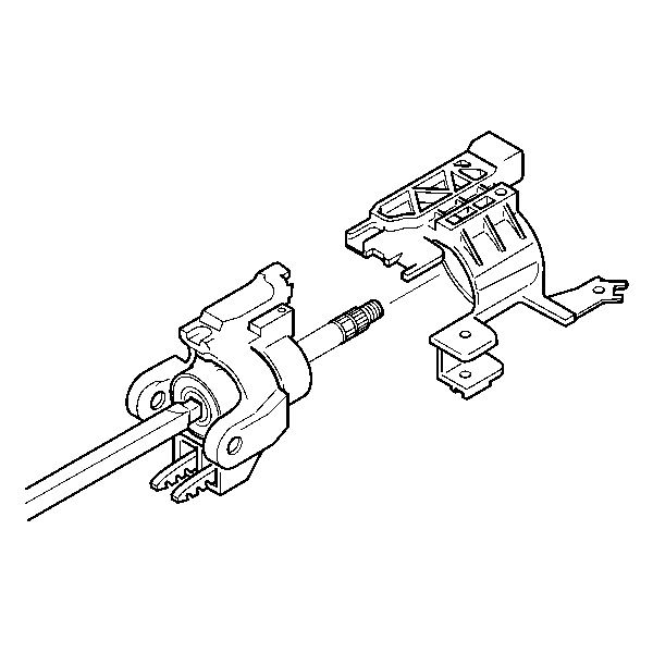
- Slide the ignition lock cylinder case bracket off of the steering
column shaft assembly.

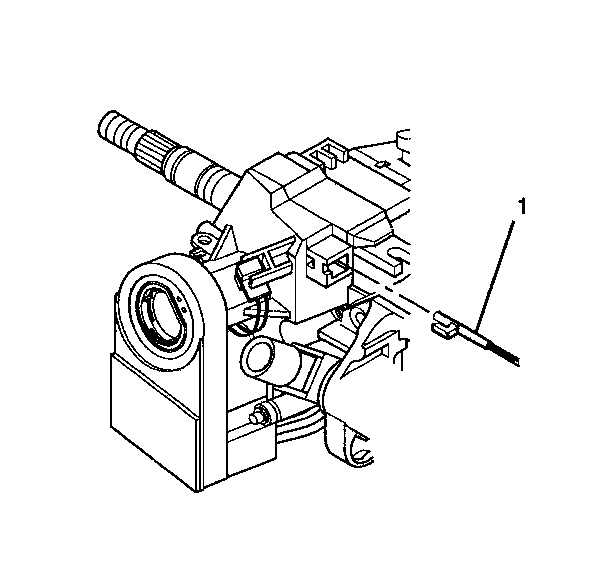
- Remove the park lock cable
assembly (1) from the ignition lock cylinder case in the following
way:
| 7.1. | Place the steering column lock cylinder set into the OFF position. |
| 7.2. | Place the shift lever clevis into the PARK position. |
| 7.3. | Use a small blade to push against the locking tab on the end of
the park lock cable assembly (1). |
| 7.4. | Disconnect the park lock cable assembly (1) from the ignition
lock cylinder case. |

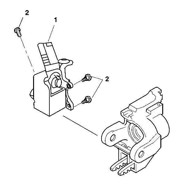
- Remove the 3 TORX®
screws (2) from the ignition lock cylinder case (1).
- Remove the ignition lock cylinder case (1) from the steering
column tilt head assembly.
Installation Procedure

- Align the ignition lock
cylinder case (1) with the steering column tilt head assembly.
Notice: Refer to Fastener Notice in the Preface section.
- Screw the 3 TORX® screws (2) into the ignition lock
cylinder case (1).
Tighten
Tighten the 3 TORX® screws to 7 N·m (62 lb in).

- Place steering column
lock cylinder set into the OFF position.
- Place the shift lever clevis into the PARK position.
- Press the locking tab on the end of the park lock cable assembly (1)
into the slot in the ignition lock cylinder case.

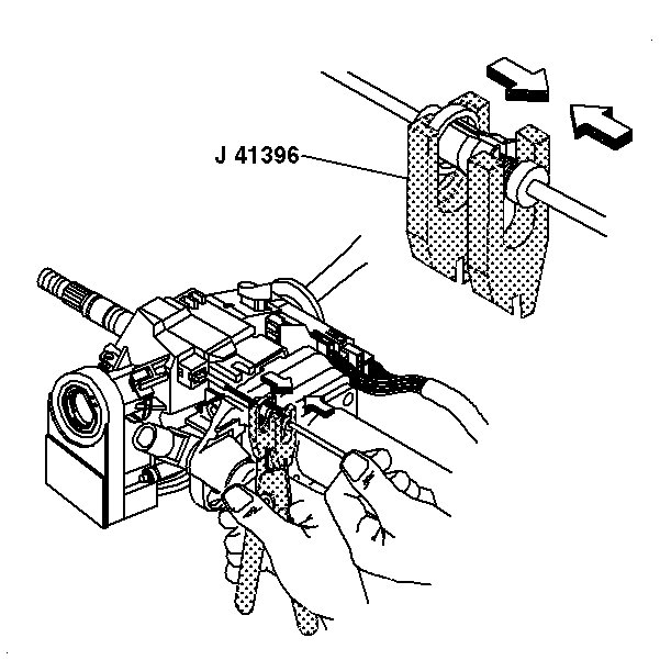
- Adjust the park lock cable
assembly.
| 6.1. | Use the gear shift lever to put the column in the PARK position. |
| 6.2. | Put the ignition switch in the OFF-LOCK position. Remove the key. |
| 6.3. | Unlock the adjuster ring on the park lock cable assembly with
J 41396
. |
| 6.4. | Pull on the cable until the park lock latch contacts the gear
shift lever. Release the cable. |
| 6.5. | Lock the adjuster ring securely in place on the park lock cable
assembly with
J 41396
. |
- Inspect the park lock cable assembly.
| 7.1. | Using the ignition lock cylinder, put the lock cylinder in the
OFF-LOCK position. The gear shift lever should not be able to shift out of
the PARK position. |
| 7.2. | Turn the key to the run position and put the gear shift lever
in the NEUTRAL position. |
| 7.3. | With the gear shift lever in the NEUTRAL position the lock cylinder
should not be able to go into the OFF-LOCK position. |
| 7.4. | Put the gear shift lever in the PARK position. |
| 7.5. | Remove the ignition lock cylinder. |

Important: Press the turn signal switch housing firmly against the steering column
tilt head in order for the screws from the turn signal and multifunction switch
assembly to align.
- Slide the ignition lock cylinder case bracket onto the steering column
shaft assembly.
- Install the turn signal and multifunction switch assembly only.
Refer to
Turn Signal Multifunction Switch Replacement
.
- Install the steering column tilt head components. Refer to
Steering Column Tilt Head Housing Replacement
.
- Install the ignition switch only. Refer to
Ignition and Start Switch Replacement
.
- Install the ignition lock cylinder. Refer to
Ignition Lock Cylinder Replacement
.
- Enable the SIR system. Refer to
SIR Disabling and Enabling
in SIR.


