GM Service Manual Online
For 1990-2009 cars only
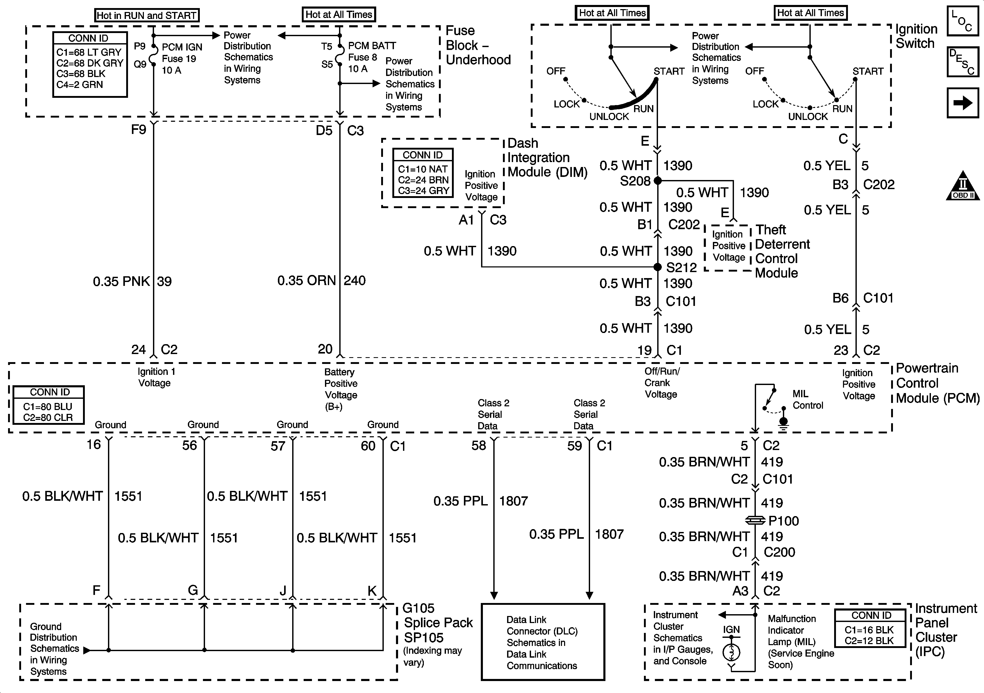
Figure 1:

Module Power, Ground, Serial Data and MIL

Object Number: 886529  Size: FS
Master Electrical Component List
Powertrain Control Module Description
Engine Data Sensors - 5 Volt and Low Reference
Engine Controls Schematic Icons
Fuse Block Underhood - Start 1 Relay, INJR 1, PCM IGN, CR CONT and INJR 2 Fuses
Fuse Block Underhood - HDLP HIBM and HDLP LOBM Relays, ABS, PCM BATT, HDHIBM, HDLOBM Fuses
Ignition Switch - 2 of 2
G104 and G105
Serial Data Class 2
Indicators
Figure 2:

Engine Data Sensors - 5-Volt and Low Reference

Object Number: 886532  Size: FS
Master Electrical Component List
Powertrain Control Module Description
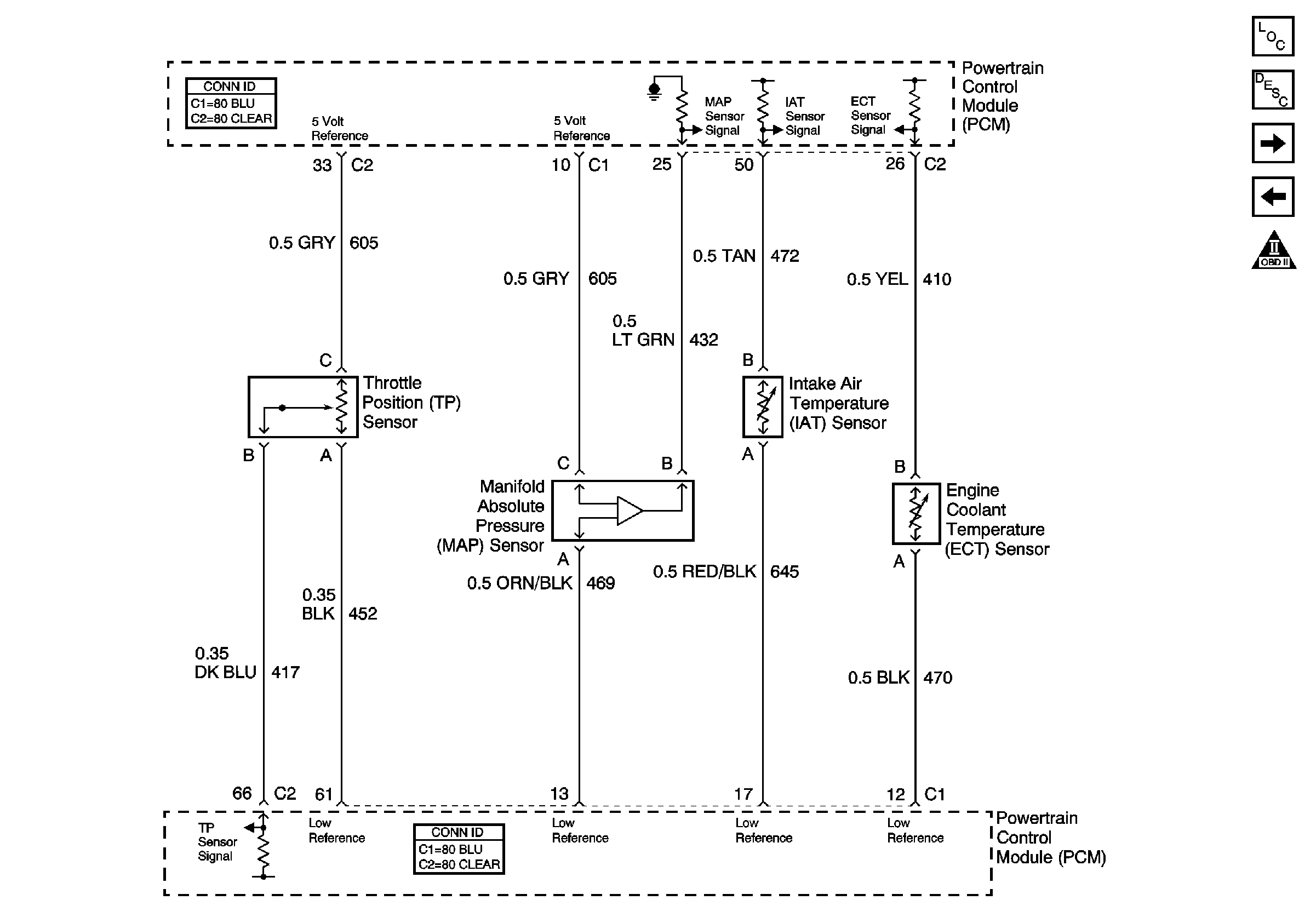
Engine Data Sensors - Pressure and Temperature
Module Power, Ground, Serial Data and MIL
Engine Controls Schematic Icons
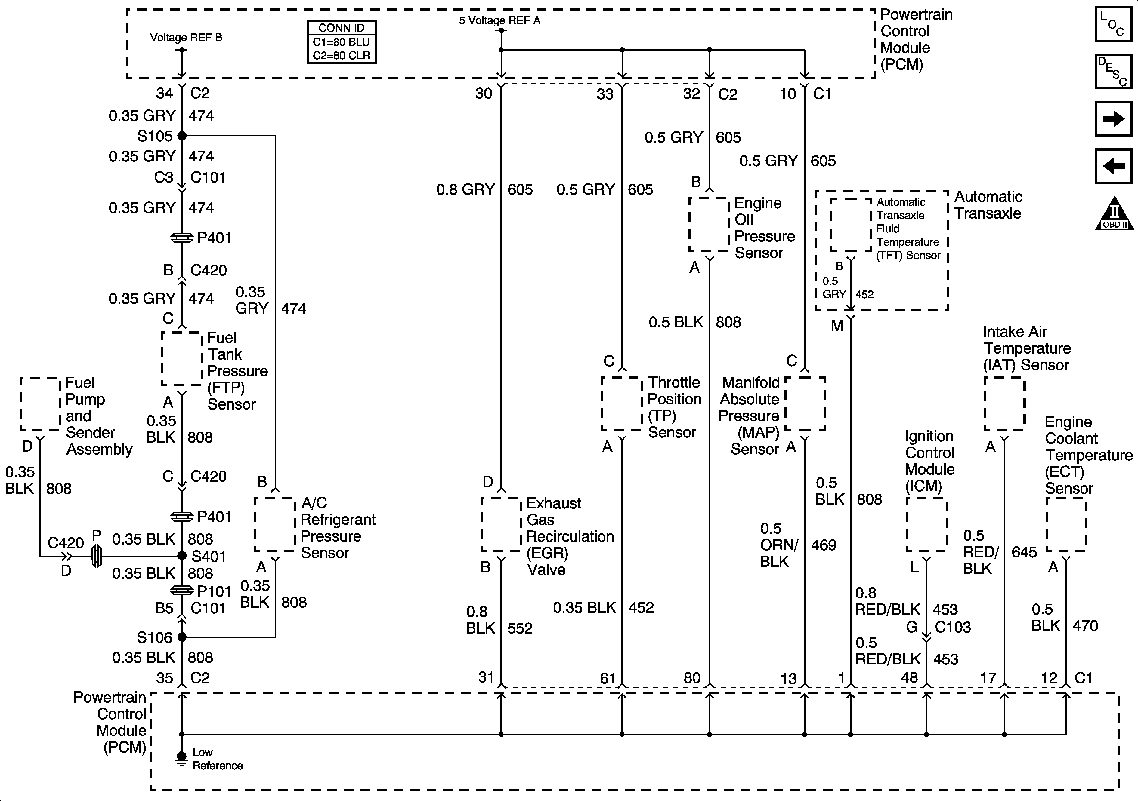
Figure 3:

Engine Data Sensors - Pressure and Temperature


Object Number: 789171  Size: FS
Master Electrical Component List
Powertrain Control Module Description
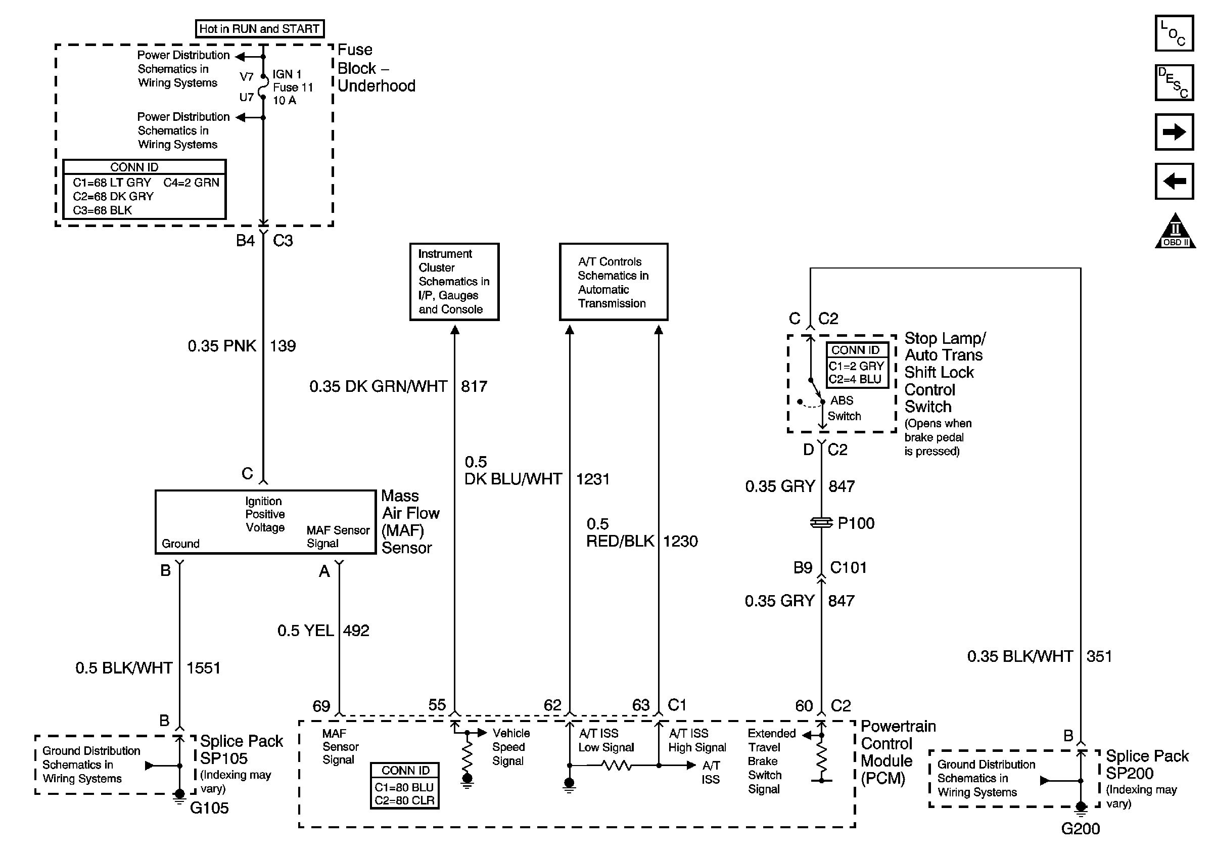
Engine Data Sensors - MAF, VSS and Extended Brake Travel Switch
Engine Data Sensors - 5 Volt and Low Reference
Engine Controls Schematic Icons
Figure 4:

Engine Data Sensors - MAF, VSS, and Extended Brake Travel Switch

Object Number: 886537  Size: FS
Master Electrical Component List
Powertrain Control Module Description
Engine Data Sensors - HO2S
Engine Data Sensors - Pressure and Temperature
Engine Controls Schematic Icons
Fuse Block Underhood - IGN 1 Relay, Transmission, DIS, OXY SEN, and IGN 1 Fuses
Gages
Transmission Inputs (L36)
G104 and G105
G200 - 1 of 2
Figure 5:

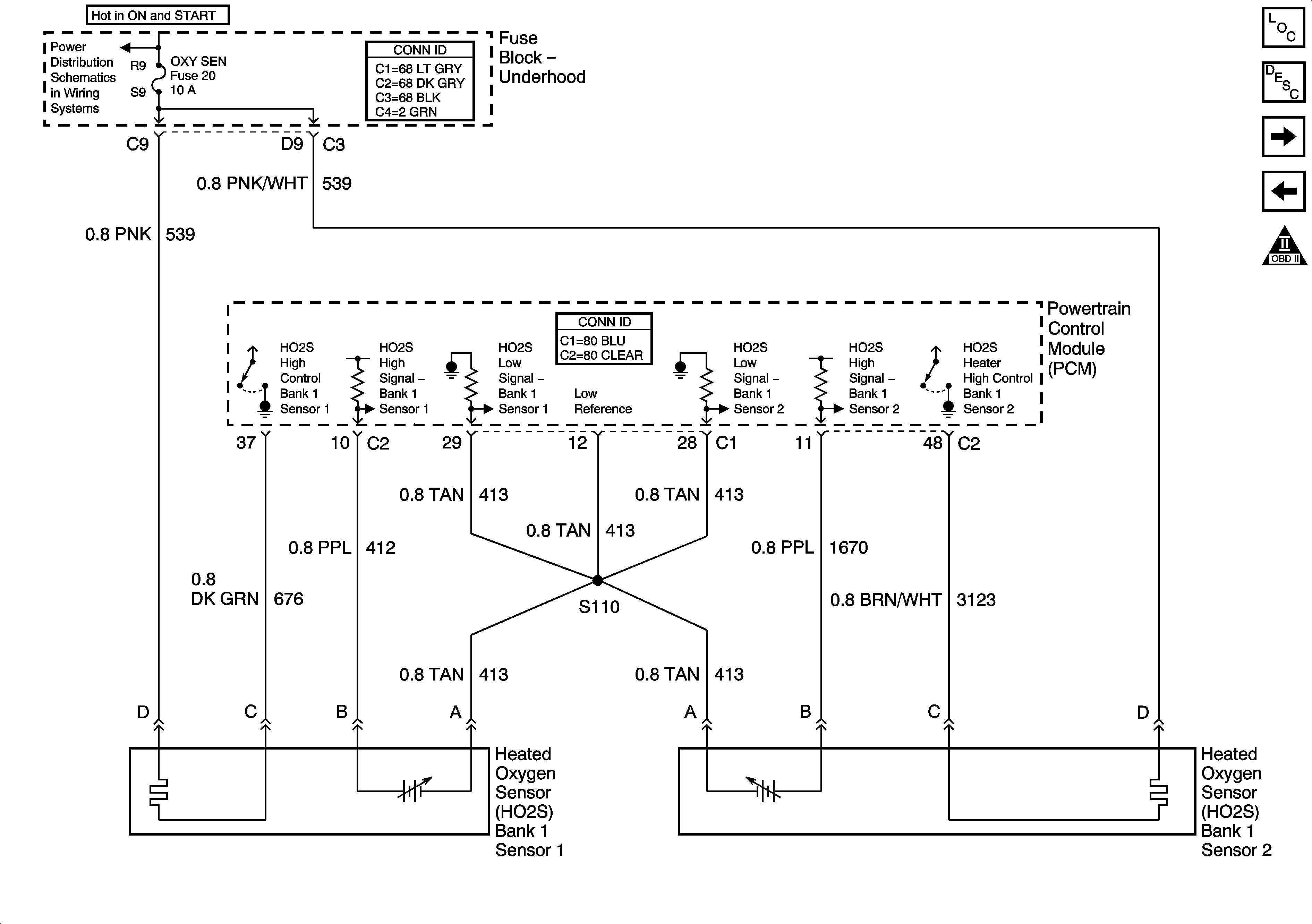
Engine Data Sensors - HO2S


Object Number: 1326867  Size: FS
Master Electrical Component List
Powertrain Control Module Description
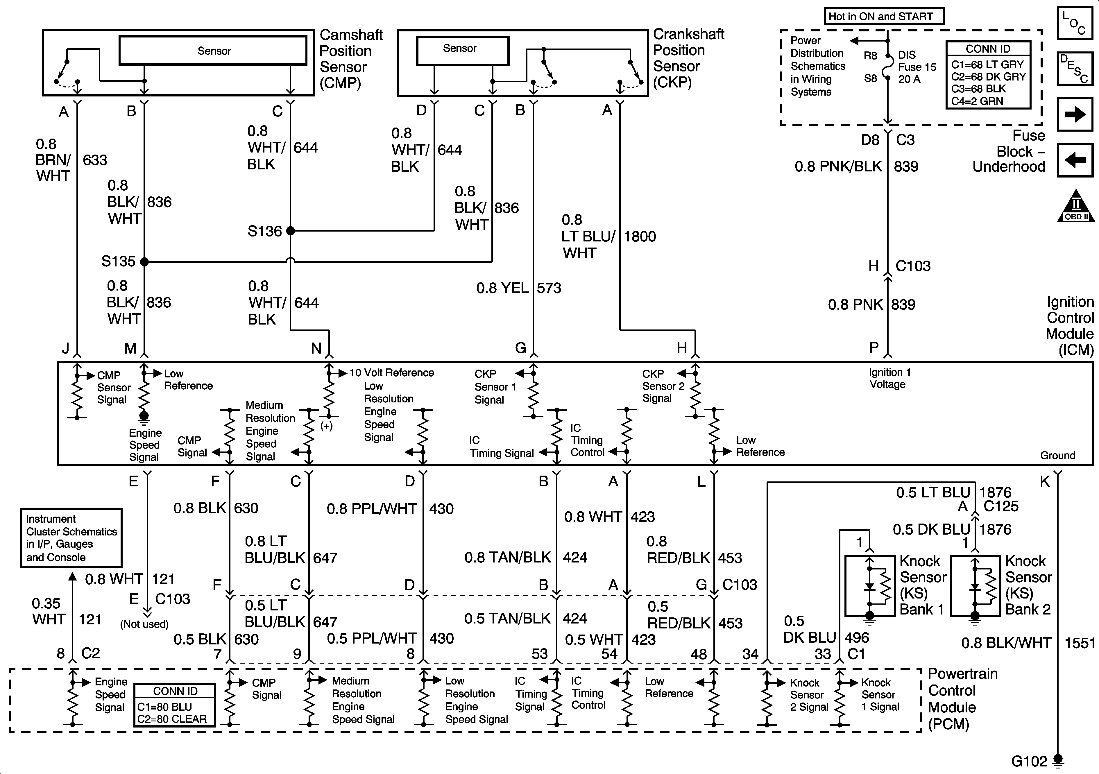
Ignition Controls - Ignition System Sensors
Engine Data Sensors - MAF, VSS and Extended Brake Travel Switch
Engine Controls Schematic Icons
Fuse Block Underhood - IGN 1 Relay, Transmission, DIS, OXY SEN, and IGN 1 Fuses
Figure 6:

Ignition Controls - Ignition System Sensors


Object Number: 886534  Size: FS
Master Electrical Component List
Electronic Ignition (EI) System Description
Fuel Controls - Fuel Pump Controls
Engine Data Sensors - HO2S
Engine Controls Schematic Icons
Gages
Fuse Block Underhood - IGN 1 Relay, Transmission, DIS, OXY SEN, and IGN 1 Fuses
Figure 7:

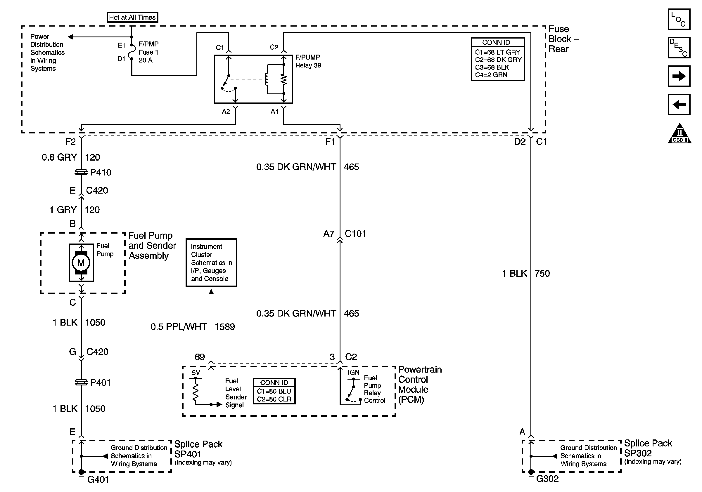
Fuel Controls - Fuel Pump Controls


Object Number: 886541  Size: FS
Master Electrical Component List
Fuel System Description
Fuel Controls - Fuel Injectors
Ignition Controls - Ignition System Sensors
Engine Controls Schematic Icons
Battery Feed to Rear Fuse Block
Gages
G401 - 2 of 2
G300 and G302
Figure 8:

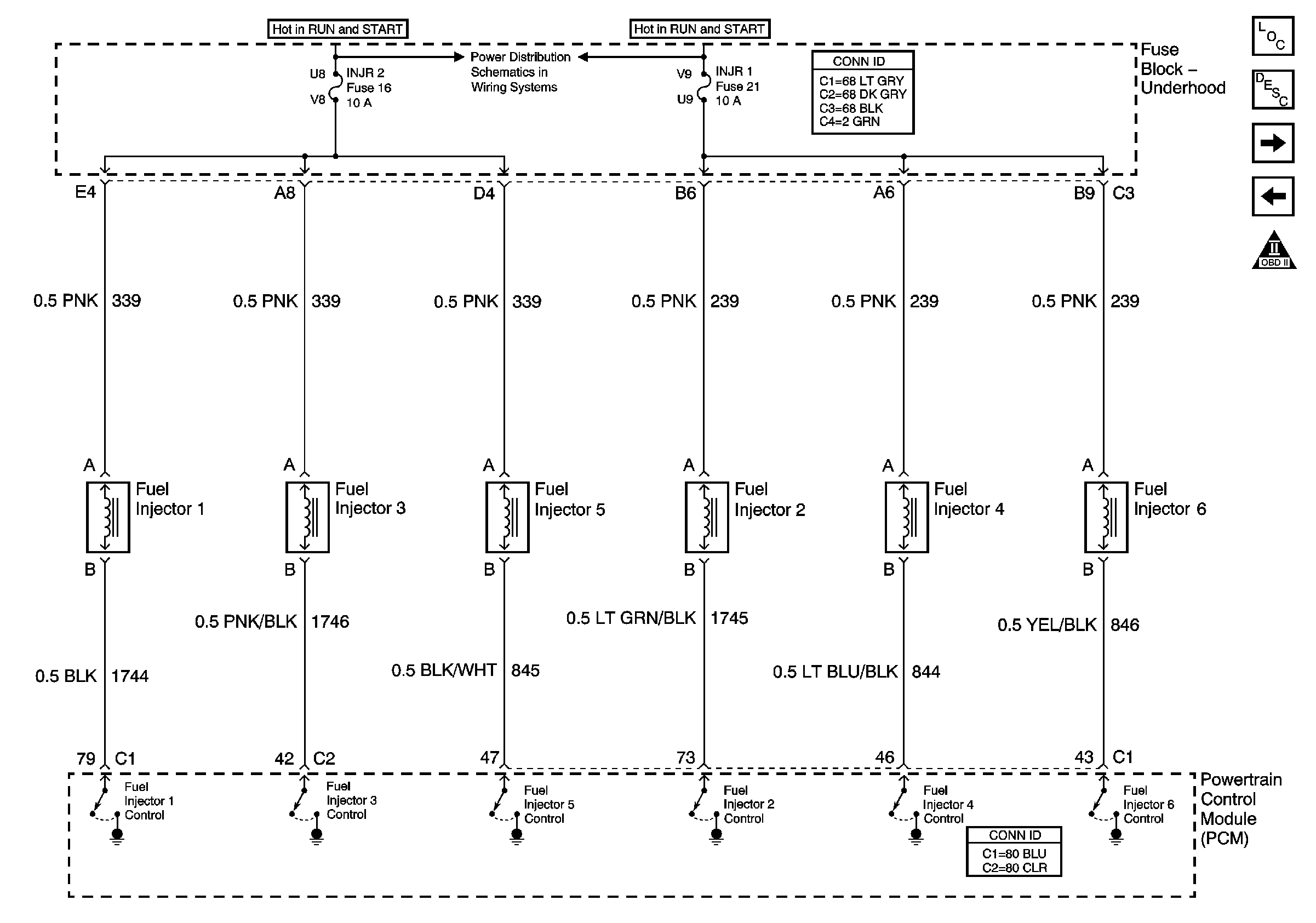
Fuel Controls - Fuel Injectors


Object Number: 886542  Size: FS
Master Electrical Component List
Fuel System Description
Fuel Controls - EVAP Controls
Fuel Controls - Fuel Pump Controls
Engine Controls Schematic Icons
Fuse Block Underhood - Start 1 Relay, INJR 1, PCM IGN, CR CONT and INJR 2 Fuses
Figure 9:

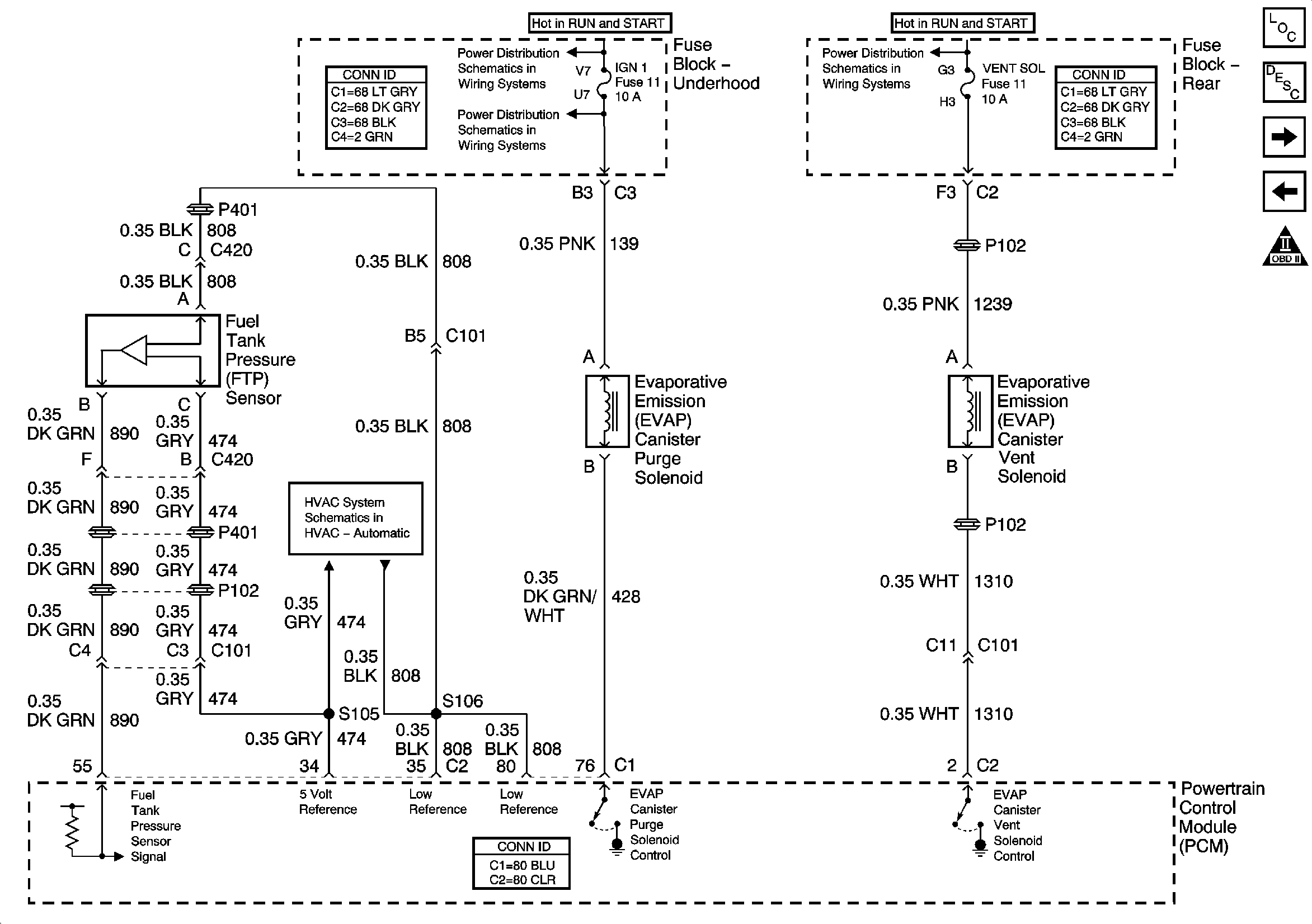
Fuel Controls - EVAP Controls


Object Number: 886546  Size: FS
Master Electrical Component List
Evaporative Emission Control System Description
Device Controls - EGR and IAC
Fuel Controls - Fuel Injectors
Engine Controls Schematic Icons
Fuse Block Underhood - IGN 1 Relay, Transmission, DIS, OXY SEN, and IGN 1 Fuses
Fuse Block Rear - IGN-1, VENT SOL and SIR Fuses
A/C Compressor Control (C67)
Figure 10:

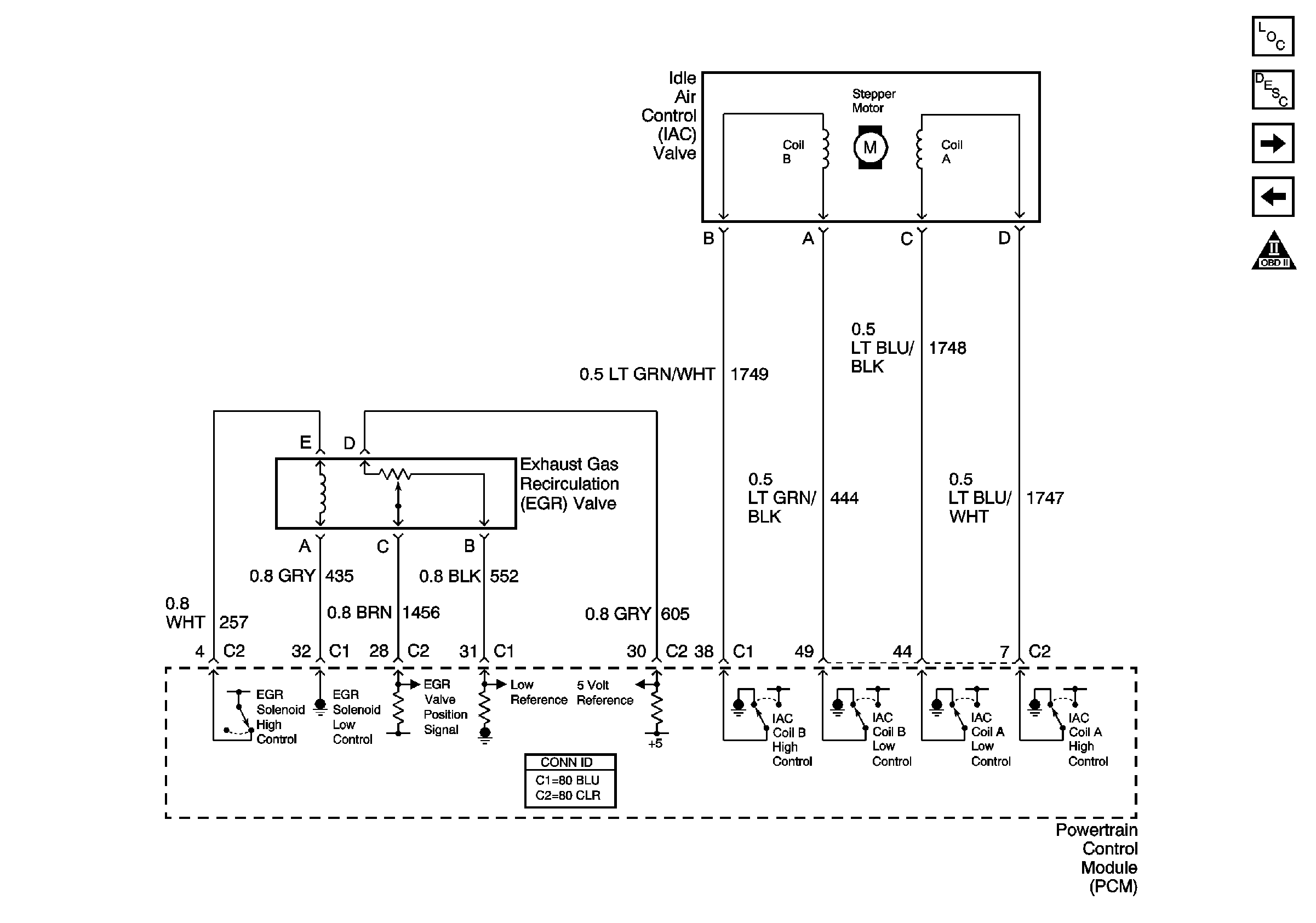
Device Controls - EGR and IAC


Object Number: 870122  Size: FS
Master Electrical Component List
Exhaust Gas Recirculation (EGR) System Description
Controlled/Monitored Subsystem References
Fuel Controls - EVAP Controls
Engine Controls Schematic Icons
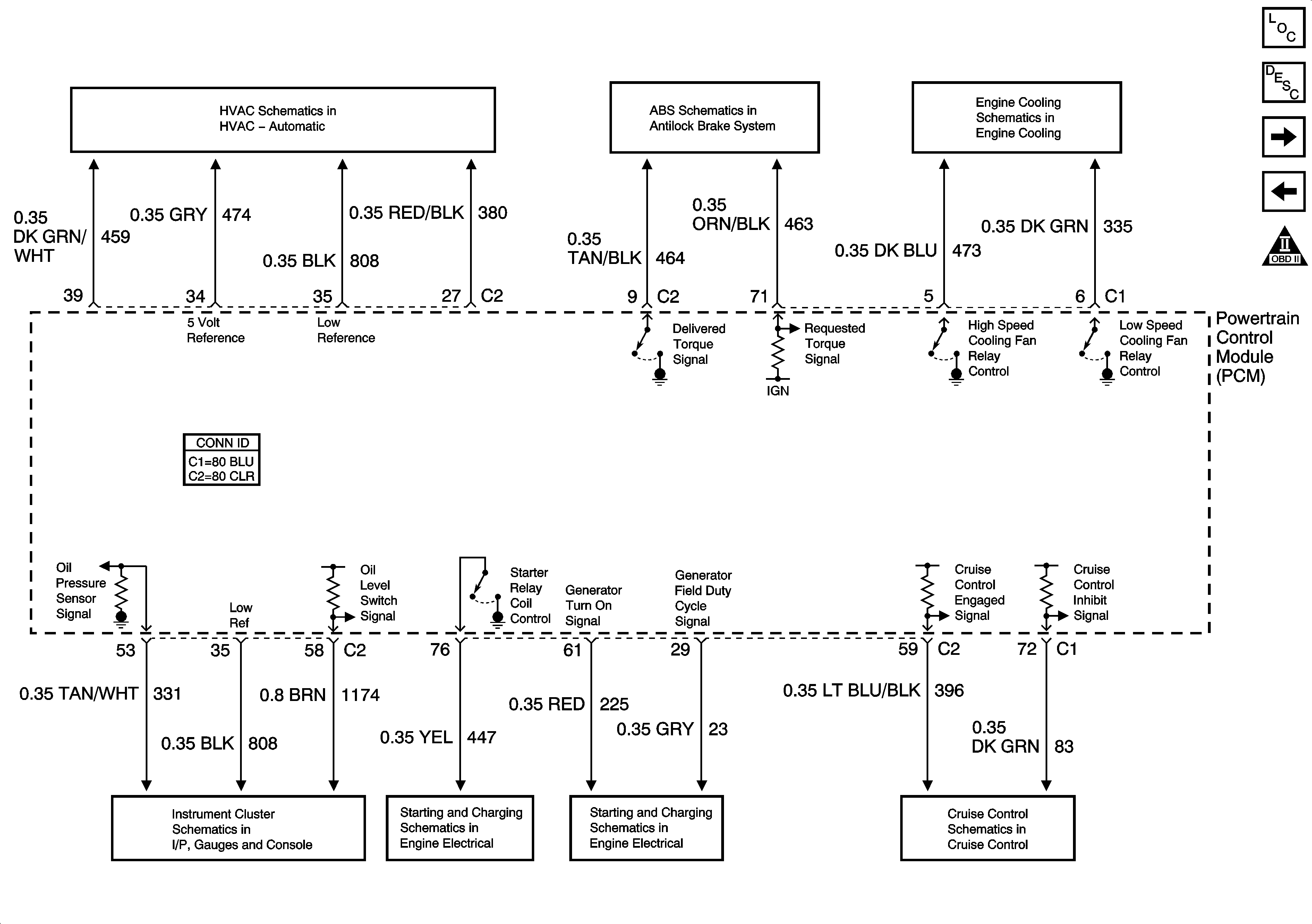
Figure 11:

Controlled/Monitored Subsystem References


Object Number: 1545395  Size: FS
Master Electrical Component List
Powertrain Control Module Description
Transmission Controls - A/T
Device Controls - EGR and IAC
Engine Controls Schematic Icons
A/C Compressor Control (C67)
Traction Control (NW9)
Cooling Fans and Relays
Indicators
Starter and Solenoid Controls
Generator Controls and Battery
CCM, PCM Controls and Vehicle Speed Input
Figure 12:

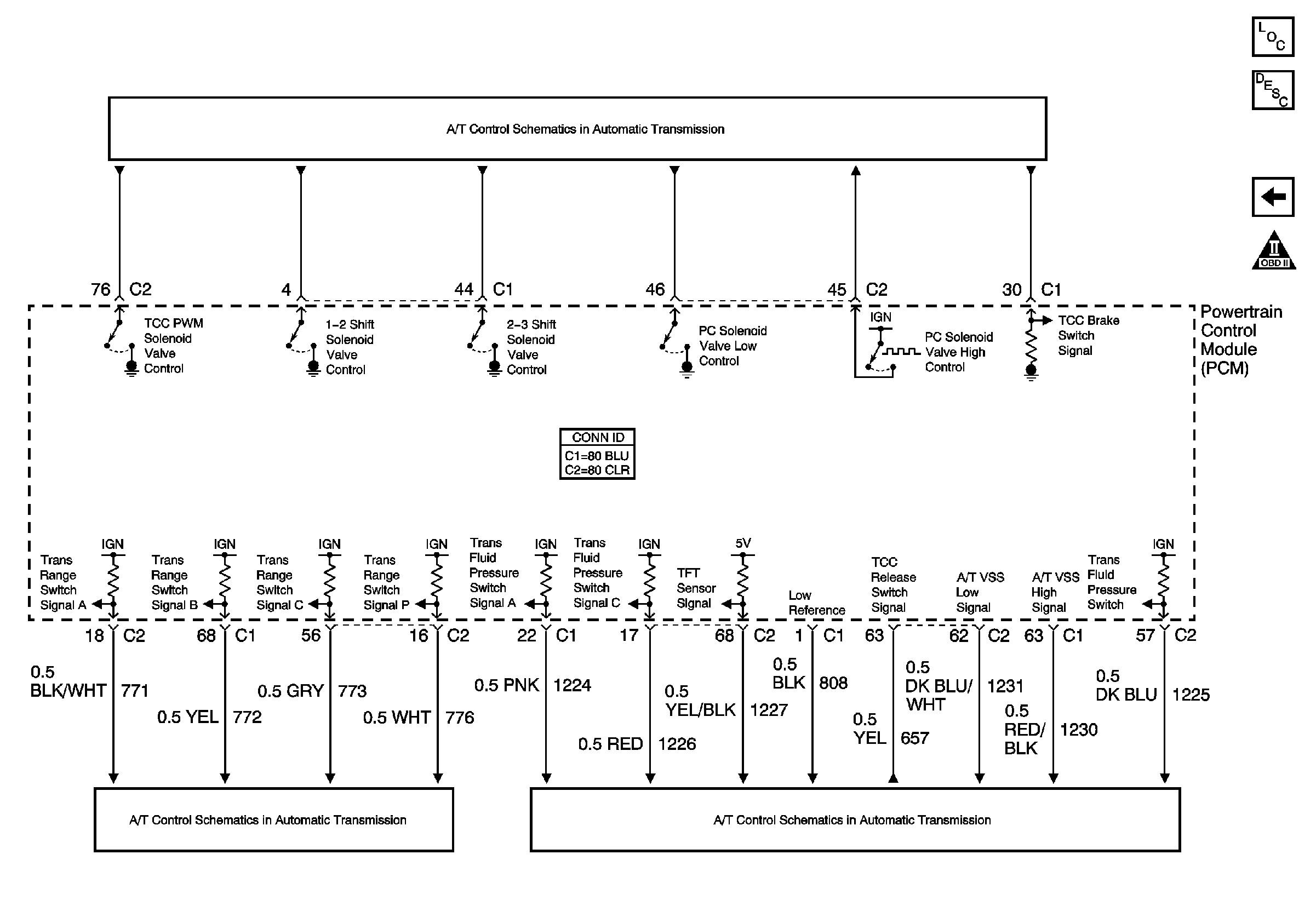
Transmission Controls - A/T


Object Number: 789192  Size: FS
Master Electrical Component List
Powertrain Control Module Description
Controlled/Monitored Subsystem References
Engine Controls Schematic Icons
Transmission Solenoids (L36)
Internal Mode Switch (IMS) Inputs
Transmission Inputs (L36)