MANUAL UPDATE-SEC.8A A/C BLOWER CONTROLS C68

VEHICLES AFFECTED: 1989 BUICK B-CAR
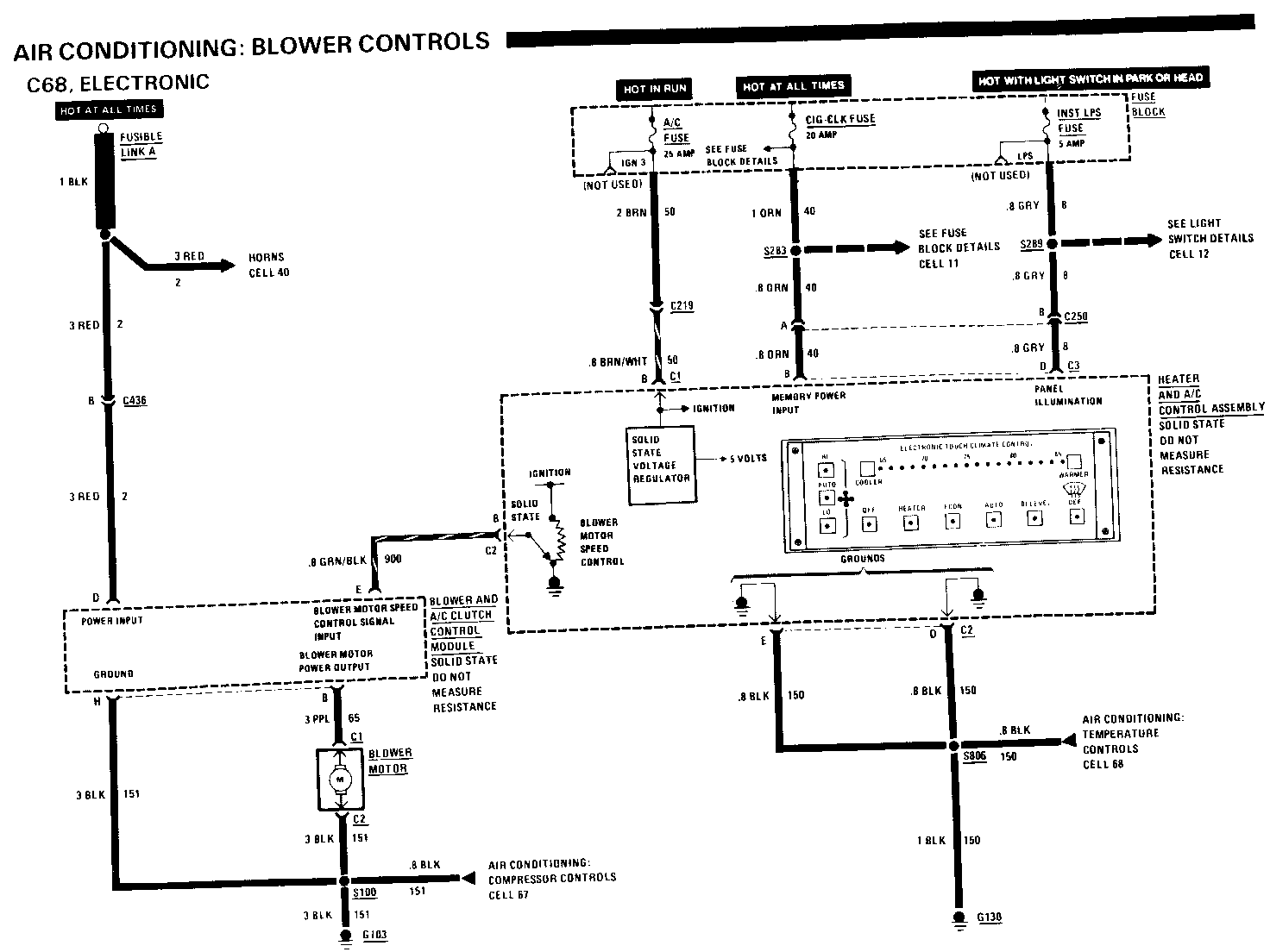
Update pages 8A-66-0,through 8A-66-5 and 8A-67-0 through 8A-67-5 to reflect the change to the Delco Electronics Power Interface Module for the C68 system. Please insert in your Service Manual.
COMPONENT LOCATION
A/C Pressure Cycling Switch RH rear of engine compartment, 201-7-E on accumulator Blower Control Module RH front of dash on plenum 201-12-A Blower Interface Module RH front of dash, on plenum Blower Motor RH front of dash 201-17-A Fuse Block Behind LH side of I/P, near shroud 201-4-A C250 (2 cavities) I/P harness, behind center of I/P 201-7-A C436 (4 cavities) Engine compartment, near rear of 201-6-C RH valve cover C999 (8 cavities) RH front of dash, on plenum C103 A/C harness, RH rear of engine 201-12-A compartment beind accumulator C130 Below R H side of I/P, left of 201-1-B grommet C100 A/C harness, RH rear of engine 201-12-A compartment behind accumulator C283 I/P harness, above RH side of radio 201-10-B C289 I/P harness, above RH side of radio 201-10-B C806 A/C harness, near Blower Motor 201-7-E
TROUBLESHOOTING HINTS
Try the following checks before doing the System Diagnosis.
1. Check A/C Fuse and CIG-CLK Fuse by visual inspection.
2. Check that grounds G103 and G130 are clean and tight.
3. Check that Blower Motor connectors are mated correctly and firmly seated.
4. Check Fusible Link A by operating the Horn.
Go to the A/C System Check in Section 8A-62 for a guide to normal operation.
Go to System Diagnosis for diagnostic tests.
SYSTEM DIAGNOSIS
Do the tests listed for your symptom in the Symptom Table below.
SYMPTOM TABLE
SYMPTOM DO TEST ------- -------- Heater and A/C A: Heater and A/C Control Assembly Control Assembly does not operate at Voltage Test all (no display)
Blower will not run C: Blower Control in any mode Module Test
Blower runs at high Check PPL wire speed only with igni- from Blower inter- tion in RUN. No low face Module to Con- speed or auto blower nector C999 for an open. If wire is ok, replace Blower inter- face Module
Heater and A/C B: Panel Illumin- Control Assembly ation Test panel illumination does not light
A: HEATER AND A/C CONTROL ASSEMBLY VOLTAGE TEST
Measure: VOLTAGE
AT: HEATER AND A/C CONTROL ASSEMBLY CONNECTORS C1 & C2 (Disconnected)
Conditions:
Ignition Switch: RUN
Measure Correct For Between Voltage Diagnosis ------- ------- --------- C1/B (BRN/ WHT) & Battery See 1 Ground
C3/B (ORN) Battery See 2 &Ground
C3/B (ORN) Battery See 3 & C2/D (BLK)
C3/B (ORN) Battery See 3 & C2/E (BLK)
If all voltages are correct, replace the Heater and A/C Control Assembly
1. Check/repair BRN/WHT and BRN (50) wire for an open or short to ground
2. Check/repair ORN (40) wire for an open or short to ground
3. Check/repair BLK (150) wire for an open
B: PANEL ILLUMINATION TEST
Measure: VOLTAGE
AT: HEATER AND A/C CONTROL ASSEMBLY CONNECTOR C3, (Disconnected)
Conditions:
-Light Switch: PARK -Dimmer Switch: FULL BRIGHTNESS
Measure Correct For Between Voltage Diagnosis ------- ------- --------- C3/D (GRY) Battery See 1 & Ground
If voltage is correct, replace Heater and A/C Control Assembly
1. Check/repair GRY (8) wire for an open
C: BLOWER CONTROL MODULE TEST (TABLE 1)
Measurs: VOLTAGE
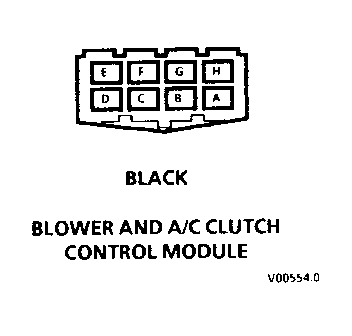
AT: BLOWER CONTROL MODULE CONNECTORS C1 & C2 (Disconnected)
Conditions:
-Ignition Switch: RUN -Blower: HI
Measure Correct For Between Voltage Diagnosis ------- -------- ---------- C1/B (RED) Battery See 1 & Ground
C1/B (RED) Battery See 2 & C2/C (BLK)
C2/B (GRY) Battery See 3 & Ground
If all voltages are correct, go to Table 2
1. Check/repair RED (2) wire and Fusible Link A for an open or short to ground
2. Check/repair BLK (151) wire for an open
3. Go to Test E: Blower Interface Test
C: BLOWER CONTROL MODULE TEST (TABLE 2)
Connect: FUSED JUMPER
AT: BLOWER CONTROL MODULE CONNECTORS C1 & C2 (Disconnected)
Connect Correct For Between Result Diagnosis ------- ------ --------- C1/B (RED) Blower See 1 & C2/A (PPL) Motor runs
If result is correct, replace Blower Control Module
1. Go LO Test D: Blower Motor Test
D: BLOWER MOTOR TEST
Measure: VOLTAGE AT: BLOWER MOTOR CONNECTORS (Connected) Conditions:
-Ignition Switch: RUN -Blower: Hi
Measure Correct For Between Voltage Diagnosis ------- ------- --------- C1 (PPL) Battery See 1 &Ground
C1 (PPL) Battery See 2 & C2 (BLK)
If all voltages are correct, replace Blower Motor
1. Check/repair PPL (65) wire for an open or short to ground
2. Check/repair BLK (151) wire for an open
E: BLOWER INTERFACE TEST
Messure: VOLTAGE AT: CONNECTOR C999 (Disconnected) Conditions: -Ignition Switch: RUN -Blower: Hi
Measure Correct For Between Voltage Diagnosis ------- ------- --------- Y4 (BRN) Battery See 1 & Ground
X1 (GRN/ BLK)& Battery See 2 Ground
If all voltages are correct, check Blower Interface Module pigtail harness for damage. If harness is ok, replace Blower Interface Module
1. Check/repair BRN (50) wire for an open or short to ground. If wire is ok, replace Heater and A/C Control Assembly
2. Check/repair GRN/BLK (900) wire for an open or short to ground. If wire is ok, replace Heater and A/C Control Assembly
CIRCUIT OPERATION
The speed of the blower motor is determined by the voltage applied to the motor. At low Blower Motor speeds, the applied voltage is about 4 volts. As the voltages increase, the Blower Motor speed increases until maximum blower speed is reached at about 12 volts.
Blower speed is determined by the Heater and A/C Control Assembly from temperature signal inputs and the operating mode of the system. The Heater and A/C Control Assembly accepts input requests from the driver via the front panel pushbuttons.
The blower speed request from the Heater and A/C Control Assembly is outpuut at connector C2 terminal B. It is a continuously variable voltage proportional to requested blower speed. At low blower speed, the output is approximately 5 volts. At maximum blower speed, the output voltage is approximately 12 volts.
The Blower Interface Module conditions the output signal from the Heater and A/C Control Assembly. The conditioned signal is then applied to the Blower Control Module. An amplifier and driver circuit in the Blower Control Module supply a voltage of between 4 and 12 volts to the Blower Motor according to the input signal received from the Blower Interface Module.
The voltage applied at the Blower Motor is also fed back to the Blower Interface Module allowing precise speed control of the Blower Motor.
COMPONENT LOCATION
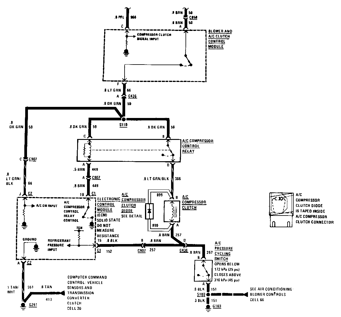
A/C Compressor Clutch RH front of engine, on A/C compressor A/C Compressor Clutch Diode Taped inside compressor clutch connector A/C Compressor Control Relay RH front of dash, on plenum A/C Pressure Cycling Switch RH rear of engine compartment, 201-7-E on accumulator Blower Control Module RH front of dash on plenum Blower Interface Module RH front of dash on plenum Electronic Control Module Behind RH side of I/P, on A/C 201-3-C (ECM) plenum Fuse Block Behind LH side of I/P, near shroud 201-4-A C219 (1 cavity) Behind I/P, near heater and A/C 201-6-B control assembly C250 (2 cavities) I/P harness, behind center of I/P 201-7-A C436 (4 cavities) Engine compartment, near rear of 201-6-C RH valve cover C858 (1 cavity) Behind center of I/P, at rear of heater and A/C control assembly C907 (3 cavities) Rear of RH valve cover 201-6-C C999 (8 cavities) RH front of dash, on plenum G103 A/C harness, RH rear of engine 201-12-A compartment behind accumulator G251 Beside rear of RH valve cover 201-6-C S100 A/C harness, RH rear of engine 201-12-A compartment behind accumulator S110 Engine hames, LH rear ofengine 201-0-C S283 I/P harness, above RH side of radio 201-10-B S289 I/P harness, above RH side of radio 201-10-B S999 Blower Interface harness, near A/C 201-7-E Compressor Control Relay
TROUBLESHOOTING HINTS
Try the following checks before doing the System Check.
1. Check CIG-CLK Fuse and A/C Fuse by visual inspection.
Go to System Check for a guide to normal operation.
Go to System Diagnosis for diagnostic tests.
SYSTEM CHECK
- Go to A/C System Check in Section 8A-62 for a guide to normal operation for the entire A/C System.
SYSTEM CHECK TABLE
ACTION NORMAL RESULT ------ ------------- 1. Turn Ignition A click can be heard Switch to RUN when Clutch engages and stan engine Press AUTO and set temperature to 60 DEG
2. Alternately press Clutch plate move- AUTO and ECON ment can be seen on several times to the front of the verify that Clutch Compressor pulley. engages in AUTO If Clutch does not en- position gage, go to Step 5. If Clutch operates normally, continue to Step 3
3. Press AUTO to Engine coolant fan engage clutch runs when Compres- sor is enpged. Air moves freely through the condenser
4. Feel the suction If there is not a wide (cold) and output temperature differ- (warm) pipes of ence after the Com- the Compressor pressor has run for several seconds, see Section 1B for Re- frigerant and Com- pressor diagnostics.
If temperature differ- ence exists, A/C Compressor and Compressor Controls are operating nor- mally
5. Turn off Ignition If pressure is low, Switch and check refer to Section 1B refrigerant pres- for Refrigerant diag- sure according to nostics. according to procedures in If refrigerant pressure Section IB is normal, isolate trouble conditions using procedures in System Diagnosis
SYSTEM DIAGNOSIS
-Do the following tests if the A/C Compressor Clutch does not operate.
-If other A/C functions, such as the Blower do not work, see 8A-66.
A: ISOLATION TEST
Connect: FUSED JUMPER
AT: A/C PRESSURE CYCLING SWITCH CONNECTOR (Disconnected)
Conditions:
-Ignition Switch: RUN -Mode: AUTO -Set temperature: Below outside temperature
Jumper Correct For Between Result Diagnosis ------- ------ --------- A (BLK) & Compressor B (BRN) Clutch see I engages
-Check for low refrigerant pressure. See Section 1B of the Service Manual. If pressure is ok, replace A/C Pressure Cycling Switch
1. Go to Test B: A/C Compressor Control Relay test
B: A/C COMPRESSOR CONTROL RELAY TEST (TABLE 1)
Measure: VOLTAGE
AT: A/C COMPRESSOR CONTROL RELAY CONNECTOR (Disconnected) -Conditions: -Ignition Switch: RUN -Mode: AUTO -Set temperature: Below outside temperature
Measure Correct For Between Voltage Diagnosis ------- ------- --------- E (BRN) Battery See 1 & Ground
D (WHT) Battery See 1 & Ground
D (WHT) & Battery See 2 F (LT BLU)
If all voltages are correct, go to Table 2
1. Check/repair BRN and WHT (50) wire for an open or short to ground. If wire is ok, replace Heater and A/C Control Assembly
2. Go to Test D: Blower Control Module Test
B: A/C COMPRESSOR CONTROL RELAY TEST (TABLE 2)
Measure: FUSED JUMPER AT: A/C COMPRESSOR CONTROL RELAY CONNECTOR (Disconnected) Conditions: -Ignition Switch: RUN -Mode: AUTO -Set temperature: Below outside temperature
Jumper Correct For Between Result Diagnosis ------- ------ --------- E (BRN)& Compressor A (LT GRN) Clutch See 1 engages
If all results are correct, replace A/C Compressor Control Relay
1. Reconnect A/C Compressor Control Relay and go to Test C: A/C Compressor Clutch Test
C: A/C COMPRESSOR CLUTCH TEST
Measure: VOLTAGE
AT: A/C COMPRESSOR CLUTCH CONNECTOR (Disconnected) Conditions: -Ignition Switch: RUN -Mode: AUTO -Set temperature: Below outside temperature
Measure Correct For Between Voltage Diagnosis ------- ------- --------- B (LT GRN/BLK) Battery See 1 &Ground
B (LT GRN/BLK) Battery See 2 & A (BRN)
If all voltages are correct, replace A/C Compressor Clutch
1. Check/repair LT GRN/BLK (366) wire for an open
2. Check/repair BRN (257) wire for an open
D: BLOWER CONTROL MODULE TEST
Measure: VOLTAGE
AT: BLOWER CONTROL MODULE CONNECTORS C1 & C2 (Disconnected)
Conditions:
-Ignition Switch: RUN -Mode: AUTO -Set temperature: Below outside temperature
Measure Correct For Between Voltage Diagnosis ------- ------- --------- C1/B (RED) Battery See 1 &Ground
C1/B (RED) & C2/C Battery See 2 (BLK)
C2/D (YEL) Battery See 3 & Ground
C1/A (LT BLU) & Battery See 4 Ground
If all voltages are correct, replace Blower Control Module
1. Check/repair RED (2) wire and Fusible Link A for an open or short to ground
2. Check/repair BLK (151) wire for an open
3. Go to Test E. Blower Interface Module Test
4. Check LT BLU wire for an open (see schematic)
E: BLOWER INTERFACE MODULE TEST
Measure: VOLTAGE AT: CONNECTOR C999 (Disconnected) Conditions: -Ignition Switch: RUN -Mode: AUTO -Set temperature: Below outside temperature
Measure Correct For Between Voltage Diagnosis ------- ------- --------- Y2 (PPL) 0 Volts See 1 &Ground
Set temperature: 85 DEG F Mode: HEAT
Y2 (PPL) Approxi- & Ground mately 6 See 2 volts
If all voltages are correct, check Blower Interface Module pigtail harness for damage. If harness is ok, replace Blower Interface Module
1. Check/repair PPL (966) wire for a short to battery. If wire is ok, replace Heater and A/C Control Assembly
2. Check/repair PPL (966) wire for an open or short to ground. If wire is ok, replace Heater and A/C Control Assembly
CIRCUIT OPERATION
The compressor for the air conditioning system is belt-driven by the engine through the A/C Compressor Clutch. The clutch allows the compressor to be disengaged when air conditioning is not required.
The Heater and A/C Control Assembly determines when the compressor clutch should be engaged. Operation of the compressor depends on the mode selected by the driver and, in the case of the AUTO mode, the set, in-car, and ambient temperatures.
When compressor operation is required, the Heater and A/C Control Assembly will signal the Blower Interface Module. The Blower Interface Module will then apply battery voltage to the Blower Control Module's compressor on input terminal (C2/D). When voltage is applied to the compressor on input terminal (C2/D), the Module will ground the A/C Compressor Control Relay coil. The relay will now energize and apply voltage to the A/C Compressor Clutch. The A/C Compressor Clutch will engage as long as refrigerant pressure is above 172 kPa (25 PSI) and below 310 kPa (45 PSI).
General Motors bulletins are intended for use by professional technicians, not a "do-it-yourselfer". They are written to inform those technicians of conditions that may occur on some vehicles, or to provide information that could assist in the proper service of a vehicle. Properly trained technicians have the equipment, tools, safety instructions and know-how to do a job properly and safely. If a condition is described, do not assume that the bulletin applies to your vehicle, or that your vehicle will have that condition. See a General Motors dealer servicing your brand of General Motors vehicle for information on whether your vehicle may benefit from the information.
