
| Subject: | Oil Leak, Lower Crankcase Reseal - RTV Sealant Procedure with Current Engine Oil Manifold / Distribution Plate |
| Models: | 2006-2008 Buick Lucerne |
| 1993-2002 Cadillac Eldorado |
| 1993-2004 Cadillac Seville |
| 1994-2005 Cadillac DeVille |
| 2004-2008 Cadillac SRX, XLR |
| 1996-2003 Oldsmobile Aurora |
| 2004-2005 Pontiac Bonneville GXP |
| with 4.0L or 4.6L V-8 Engine (VINs C, Y, 9, A -- RPOs L47, LD8, L37, LH2) |
This bulletin is being revised to add model years, models, Warranty Information, revise the Subject title line and give important information on parts with date codes. Please discard Corporate Bulletin Number 03-06-01-027 (Section 06 -- Engine/Propulsion
System).
This bulletin is being issued to inform dealers of enhancements to crankcase, oil distribution plate (Engine Oil Manifold) and oil pan sealing by using RTV sealant in the procedure below.
Important: For detailed component and engine removal information, refer to Engine Replacement Procedure in the Engine Mechanical subsection of the appropriate Service Manual or SI.
- Drain the engine coolant and engine oil from the engine.
- Remove the powertrain from the vehicle.
- Remove the drive belt.
- Remove the A/C compressor and set it aside.
- Remove the power steering pump and set it aside.
- Remove the engine from the transmission.
- Install the engine on an engine stand.
- Remove the components necessary to remove the oil pan and lower crankcase, including but not limited to the following components:
| • | Engine front cover gasket |
| • | Lower crankshaft sensor |
- Rotate the engine stand with the oil pan facing up.

- Remove the oil pan bolts.
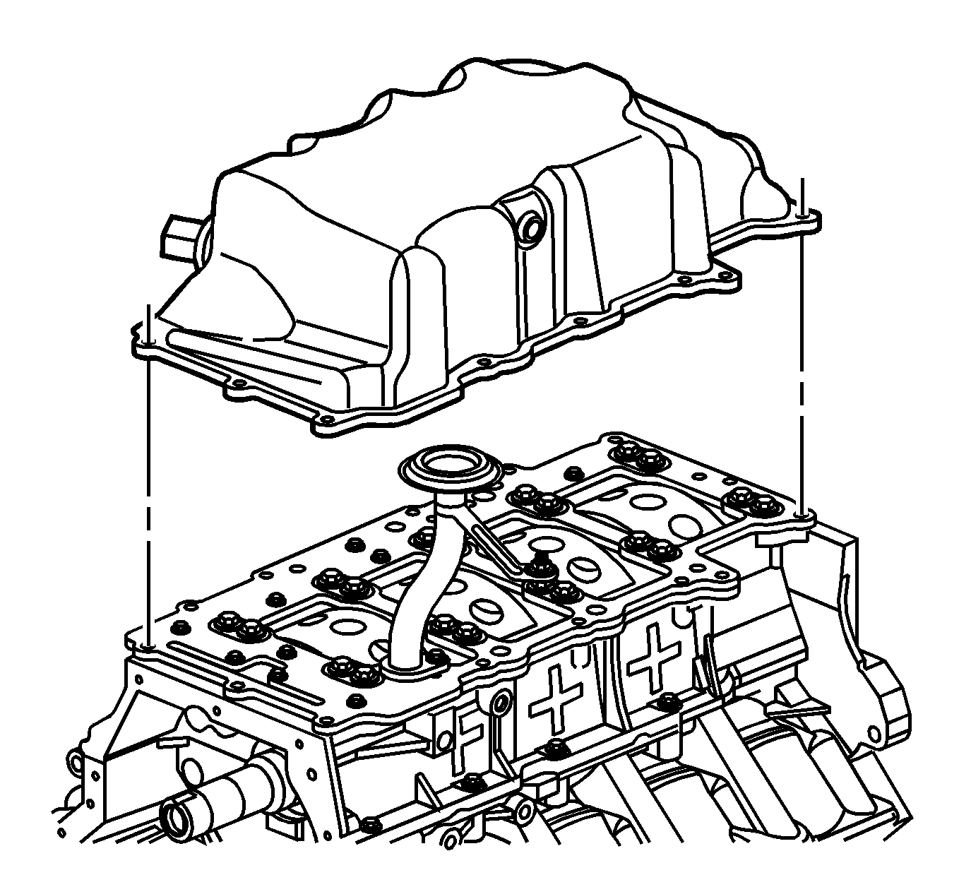
- Remove the oil pan.
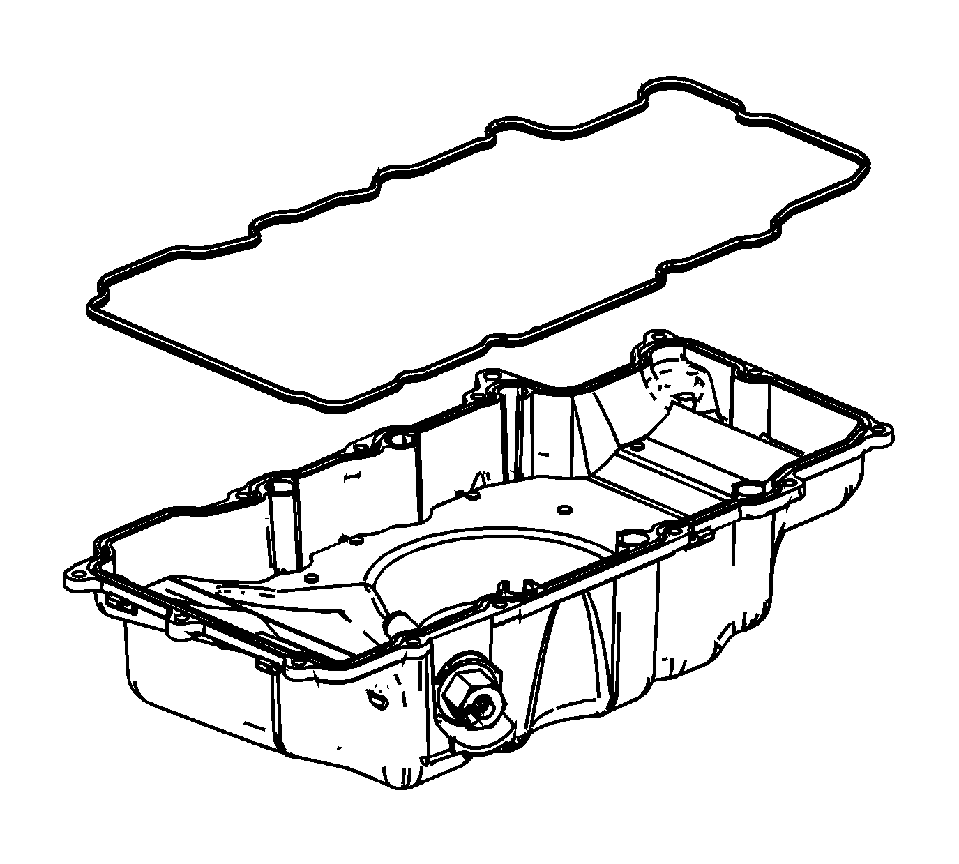
- Remove the gasket from the oil pan.
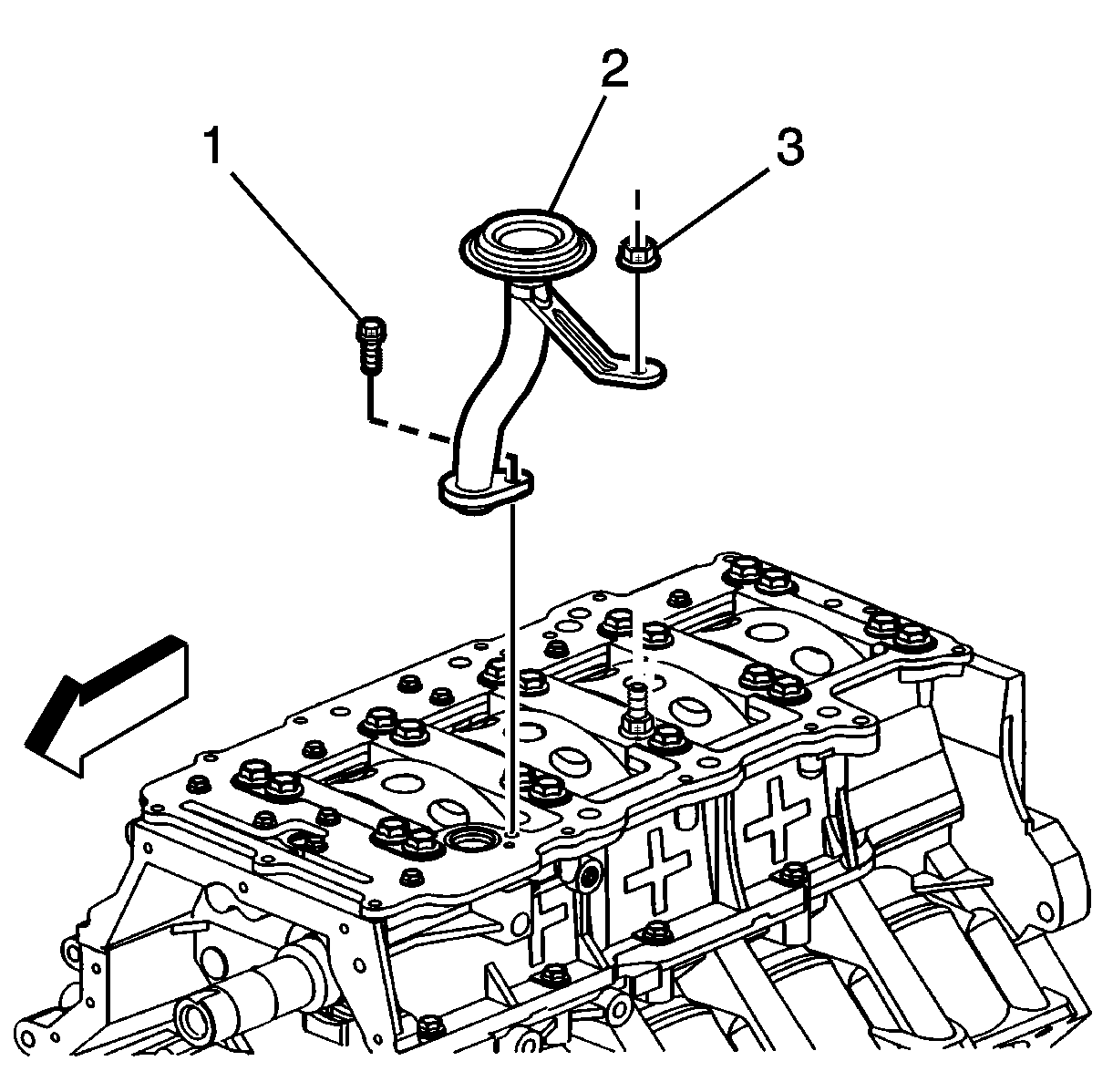
- Remove the oil suction tube bolt and nut.
- Remove the oil suction tube.
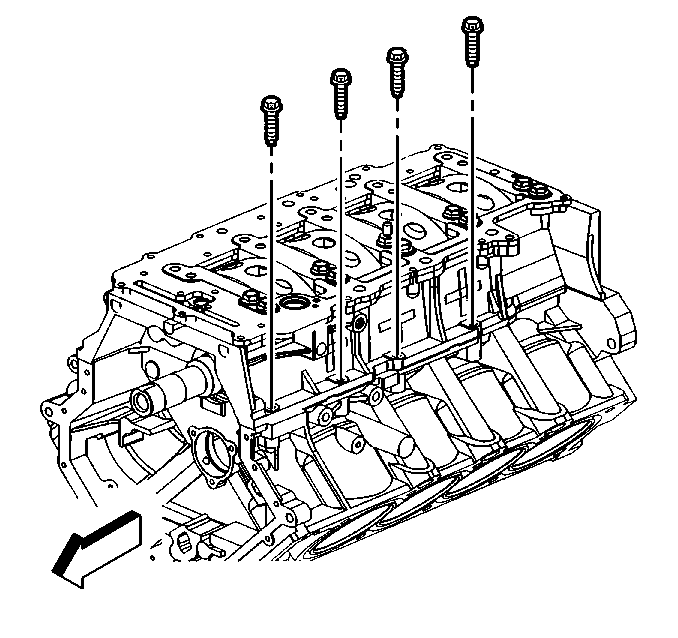
- Remove the main bearing bolts.
- Remove the crankshaft oil scraper plate.
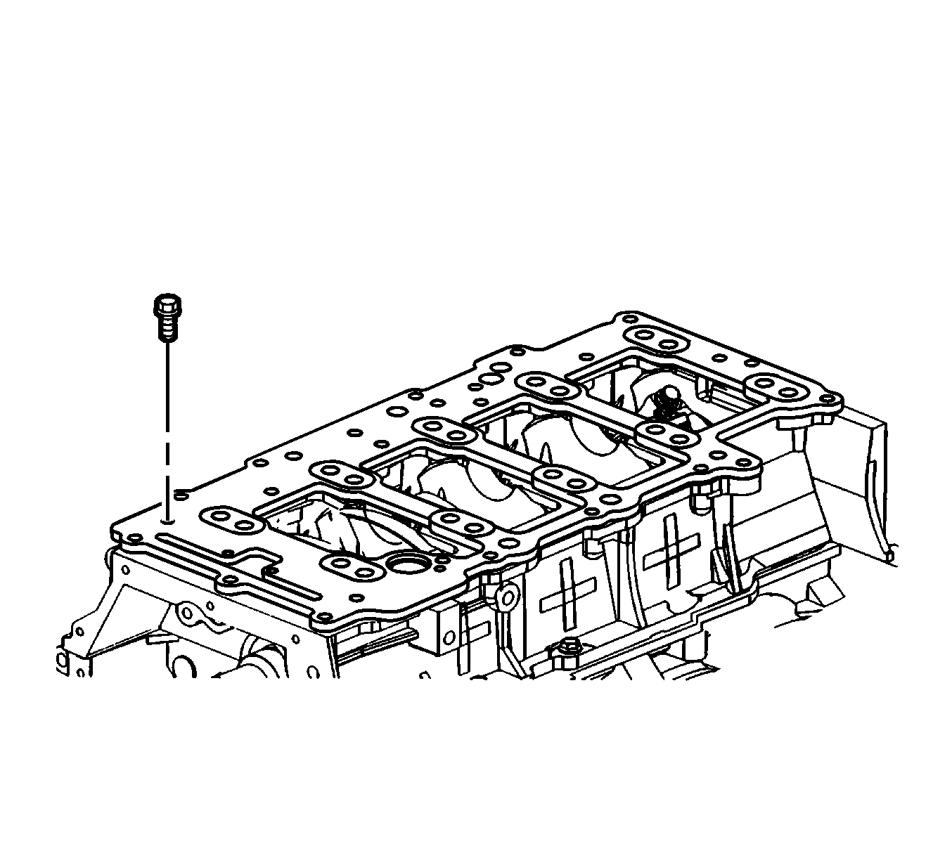
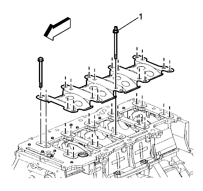
- Remove the oil distribution plate bolts.

- Remove the oil distribution plate.
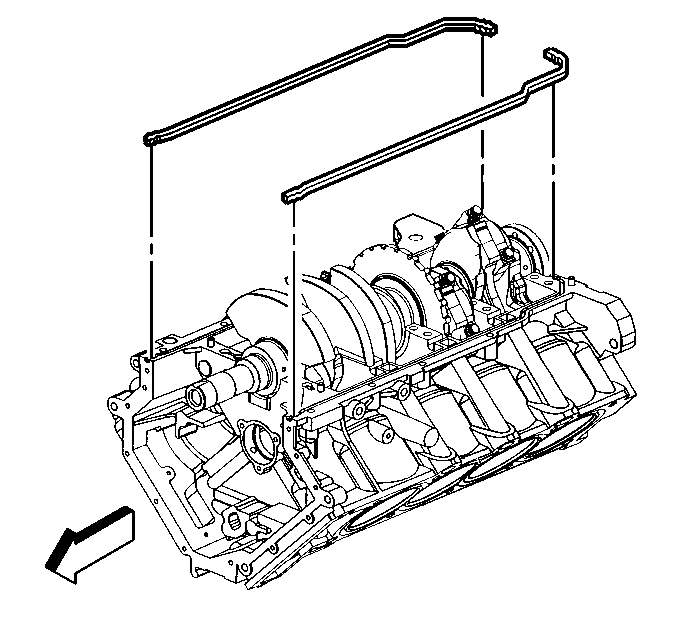
- Remove the crankcase perimeter bolts on the right side.
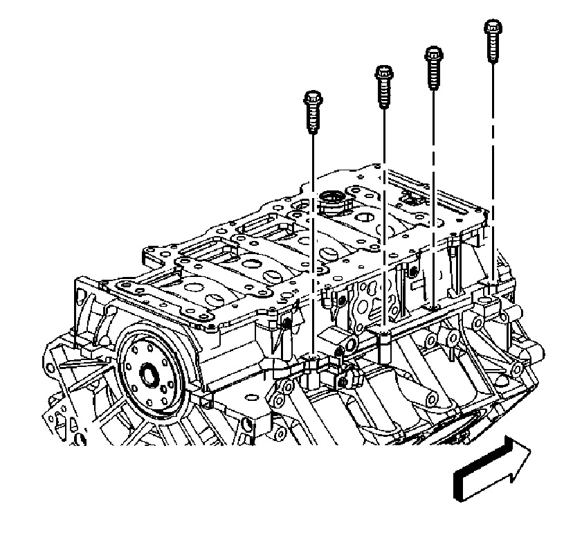
- Remove the crankcase perimeter bolts on the left side.
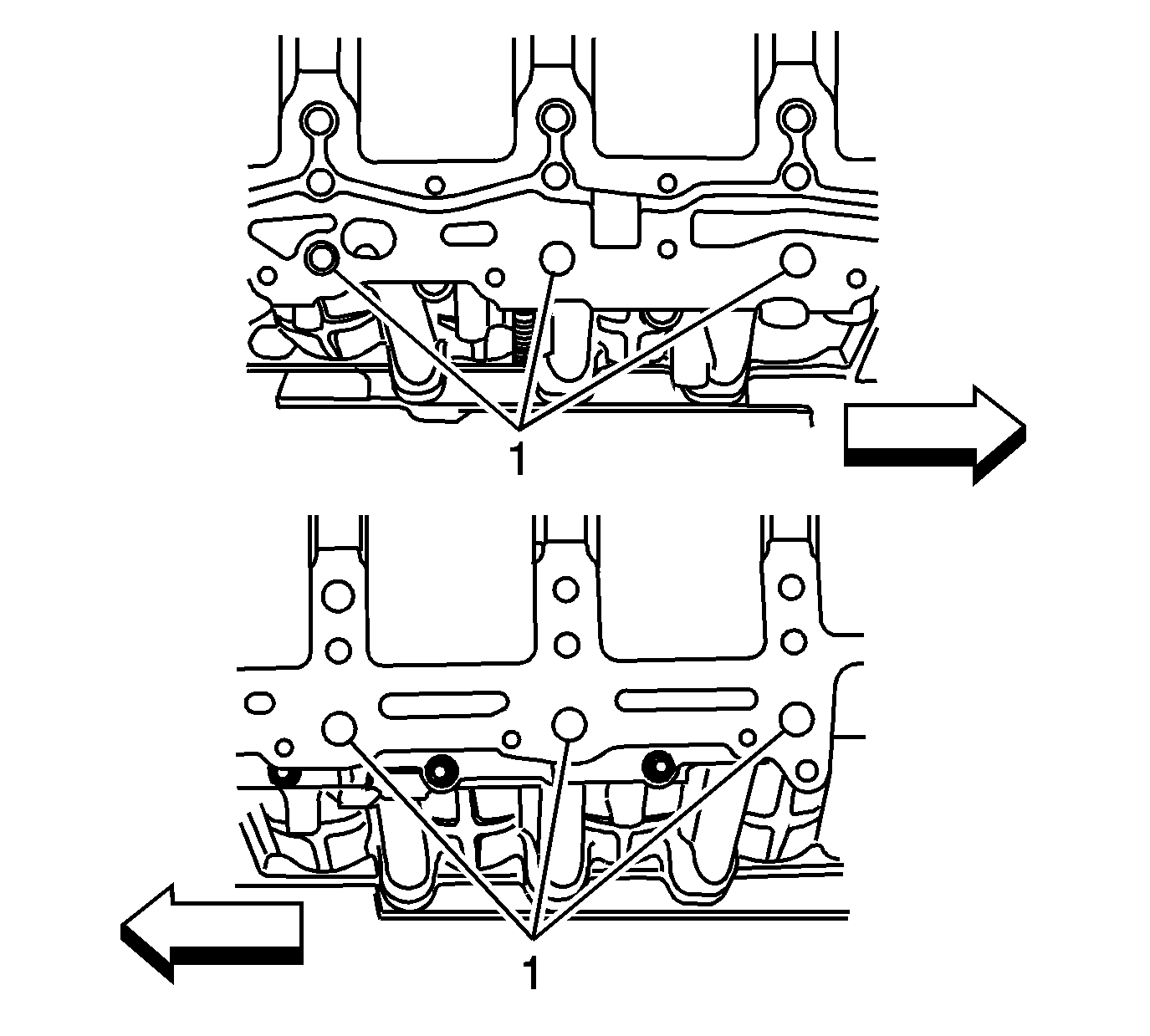
- Remove the lower crankcase by prying at the designated pry points.
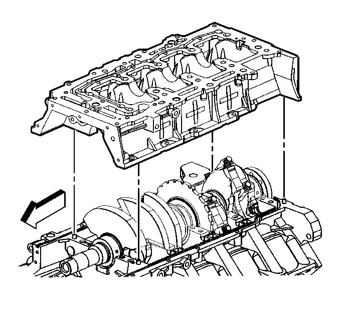
- Remove the lower crankcase.
- Remove the rear crankshaft seal. Refer to the Crankshaft Rear Oil Seal Removal procedure in SI.
- Remove the upper-to-lower crankcase seals.
- Using a suitable scraper, clean the anaerobic sealant from the rail surfaces of the block.
- Using a suitable cleaning tool, clean out the anaerobic sealant from the engine block seal groove in the rail of the block.
- Using a suitable cleaning solvent, clean the anaerobic sealant from the rail surfaces of the block.
- Using a suitable scraper, clean the anaerobic sealant from the rail surfaces of the lower crankcase.
- Using a suitable cleaning solvent, clean the anaerobic sealant from the rail surfaces of the lower crankcase.
- Ensure the surfaces to be sealed are free of anaerobic sealant and free of any nicks, gouges or scratches. Repair or replace components as necessary.
- Inspect all components removed for serviceability. Repair or replace components as necessary.
Important: Ensure components being sealed with RTV sealant are assembled within 20 minutes. Components assembled after the RTV sealant has skinned-over, approximately 20 minutes or longer, will not bond.
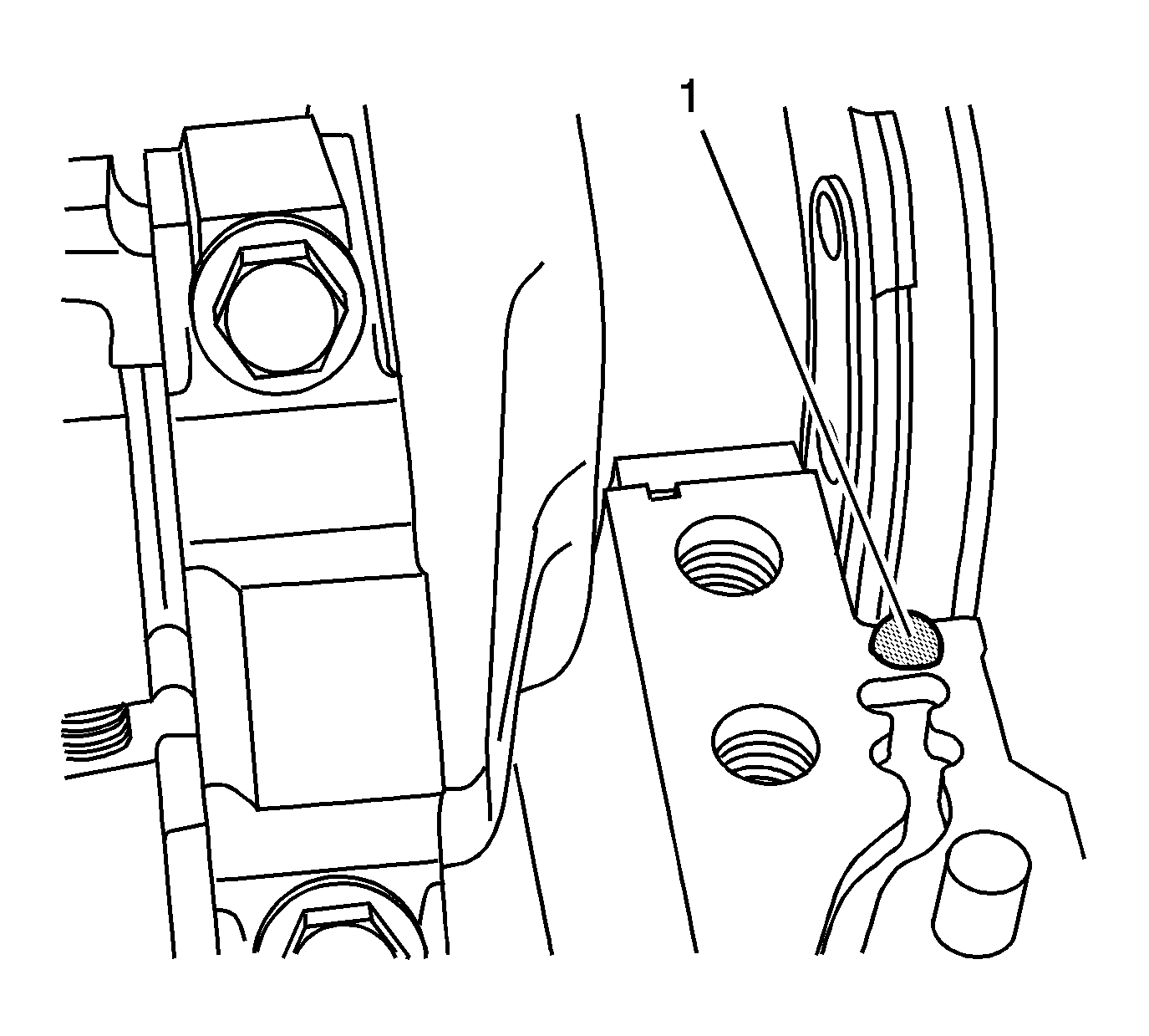
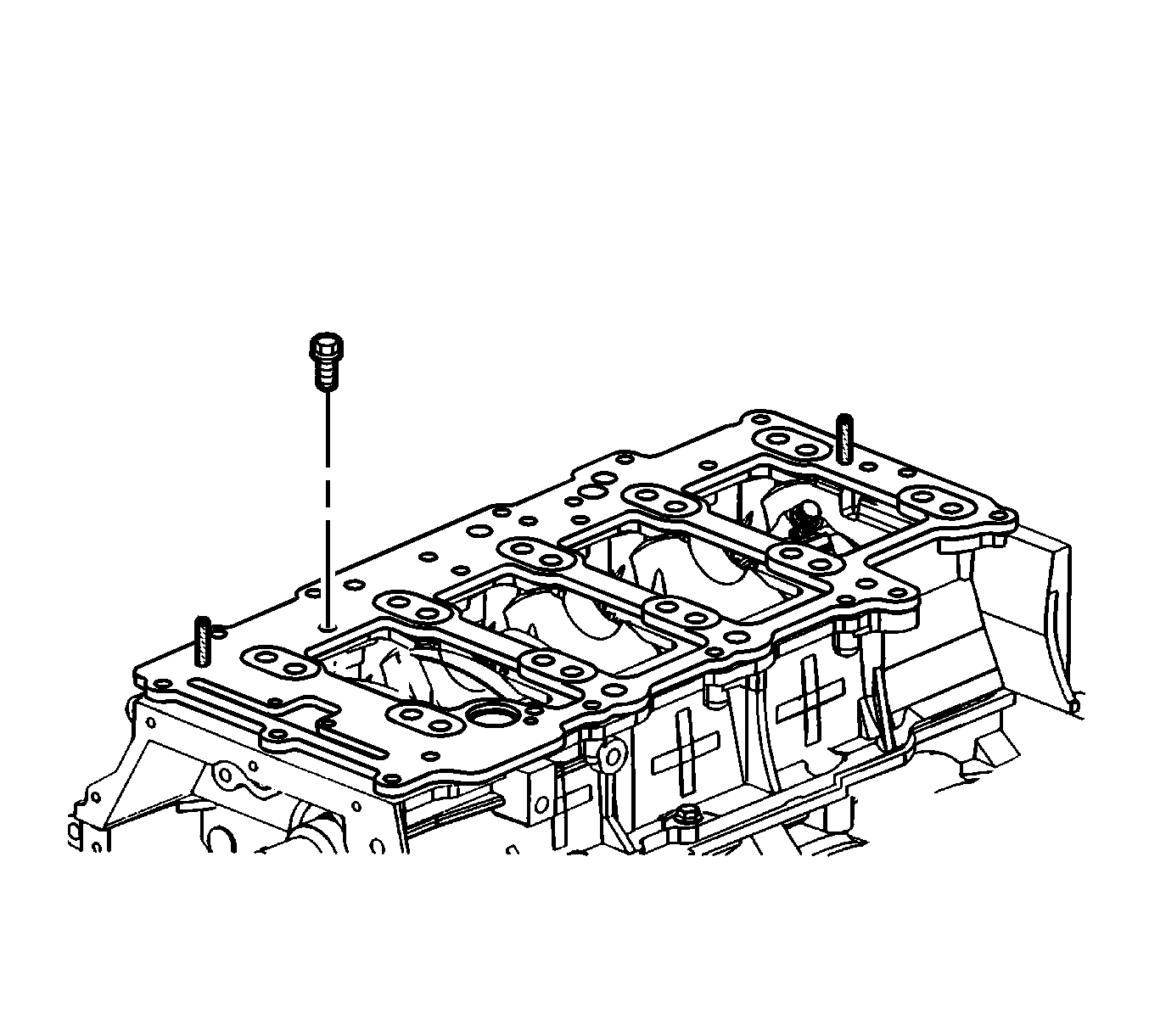
- Place a 5 mm (0.197 in) spot of RTV sealant, P/N 12378521 (in Canada, use P/N 88901148) used with a caulk gun, or P/N 88861417 (in Canada, use P/N 88861418) used with sealant dispenser GE-48326, at the two points
where the crankshaft rear oil seal meets the split line of the engine block.
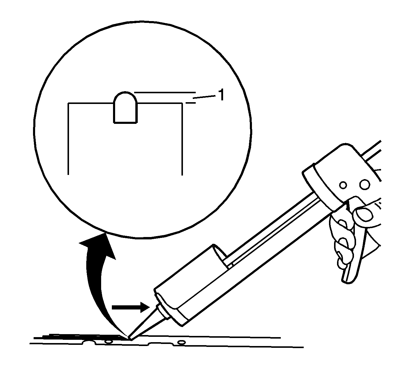
- Completely fill and slightly overfill the engine block seal groove with a continuous bead of RTV sealant, P/N 12378521 (in Canada, use P/N 88901148) or P/N 88861417 (in Canada, use 88861418).
- Ensure that the RTV sealant bead is higher than the rail surface by 3 mm (0.118 in).
- Using a suitable tool, spread the sealant in the area near the oil drain back passages away from the oil drain back passages and towards the outboard edge of the rail surface.
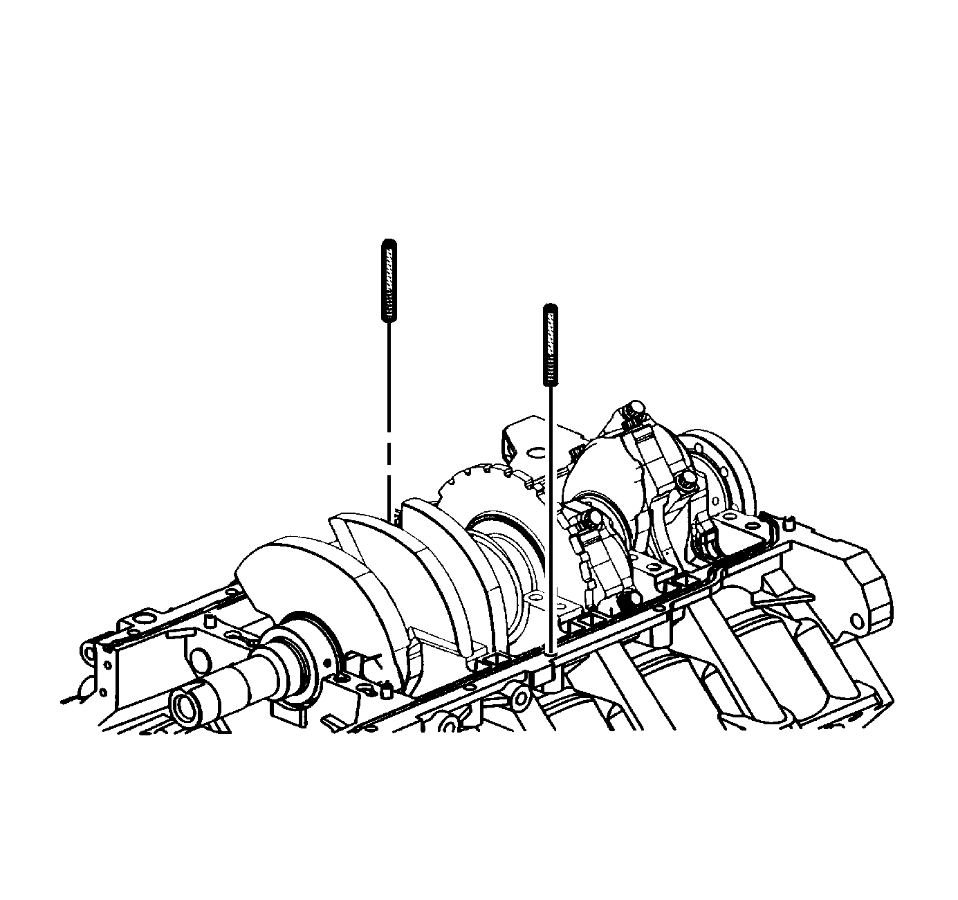
- To prevent shifting of the lower crankcase, install one of the EN 46109 tools into a bolt hole in each rail.
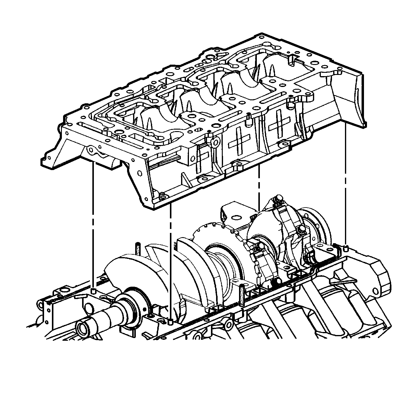
- Install the cleaned lower crankcase onto the engine.
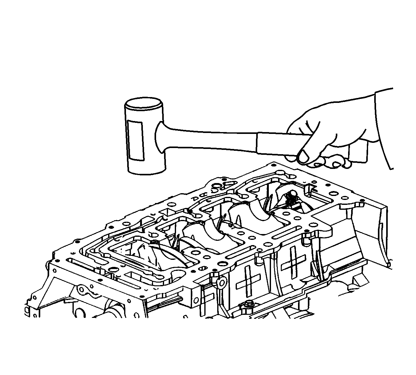
- Using a rubber mallet, gently tap the lower crankcase into position.
- Remove both EN 46109 tools.
- Loosely install the crankcase perimeter bolts on the right side.
- Loosely install the crankcase perimeter bolts on the left side.
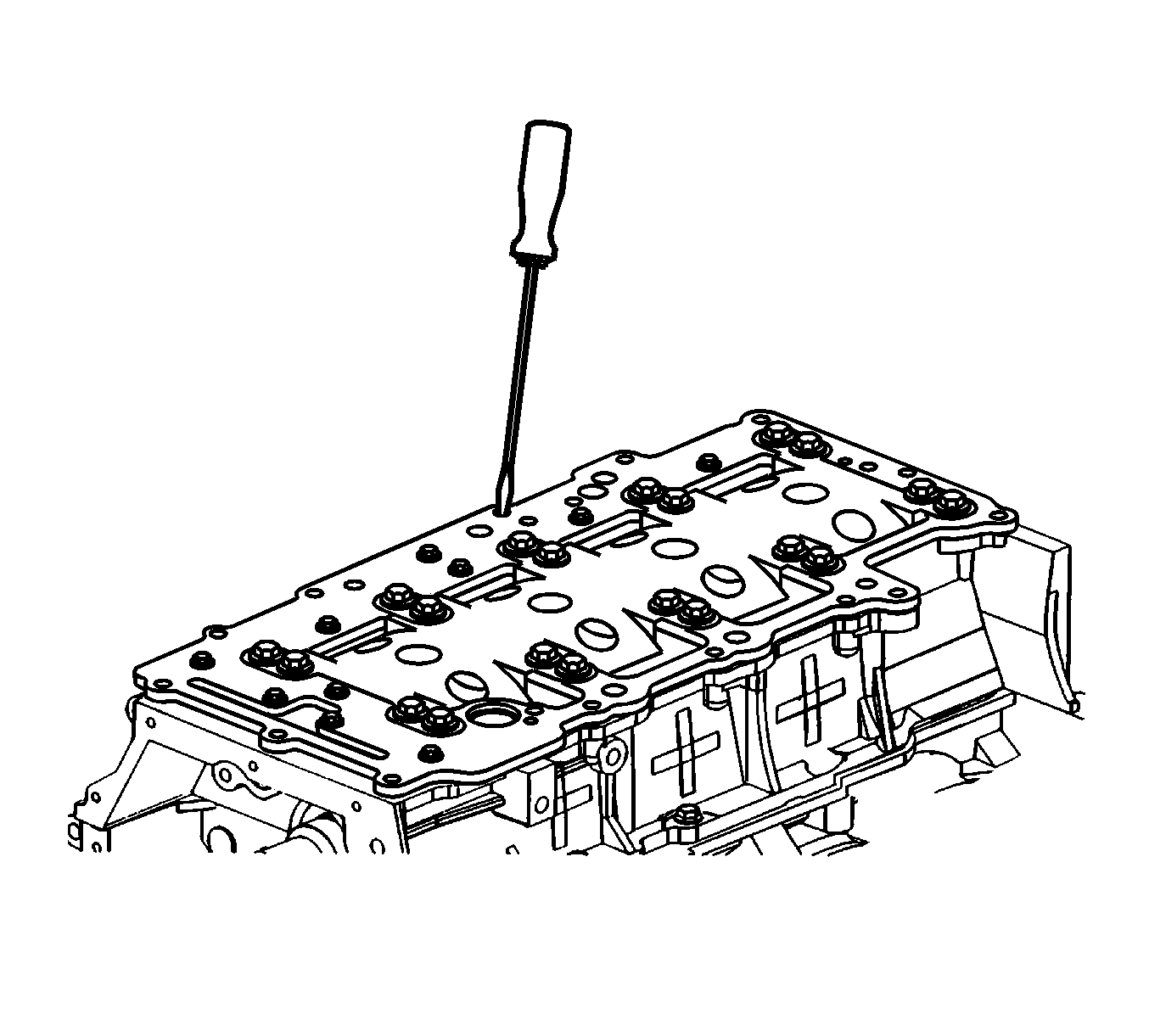
- Using a small long blade screwdriver, clean out any sealant in the oil drain back passages.
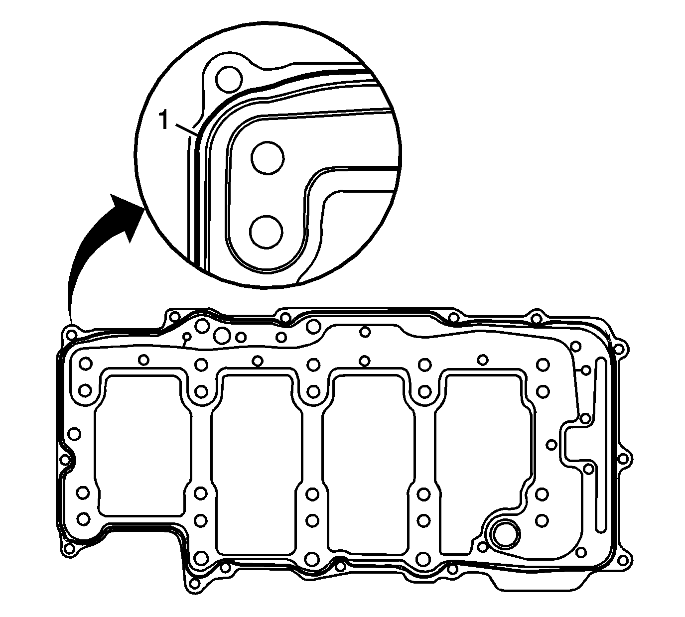
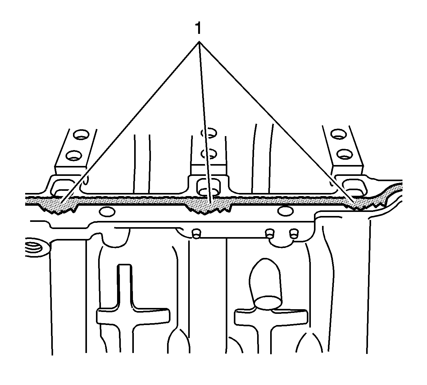
- Using a NEW oil distribution plate, place a 3 mm (0.118 in) wide bead (1) of RTV sealant, P/N 12378521 (in Canada, use P/N 88901148) or P/N 88861417 (in Canada, use 88861418), around the perimeter
of the outer seal of the oil distribution plate place.
- Ensure the RTV sealant, P/N 12378521 (in Canada, use P/N 88901148) or P/N 88861417 (in Canada, use 88861418), bead is inboard of all the oil pan bolt holes.
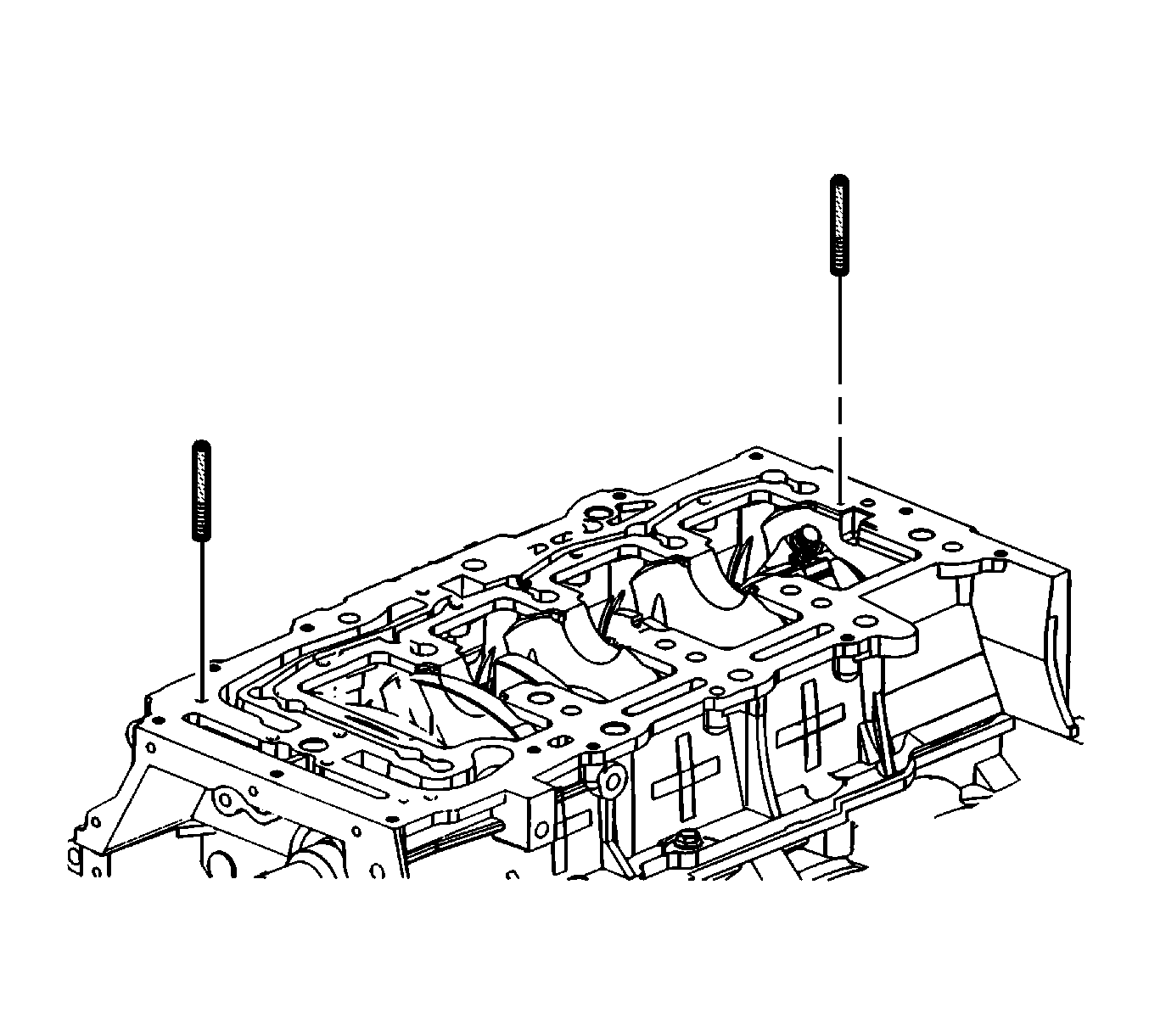
- To prevent shifting of the oil distribution plate, install one of the EN 46109 tools into a bolt hole in each side of the lower crankcase.
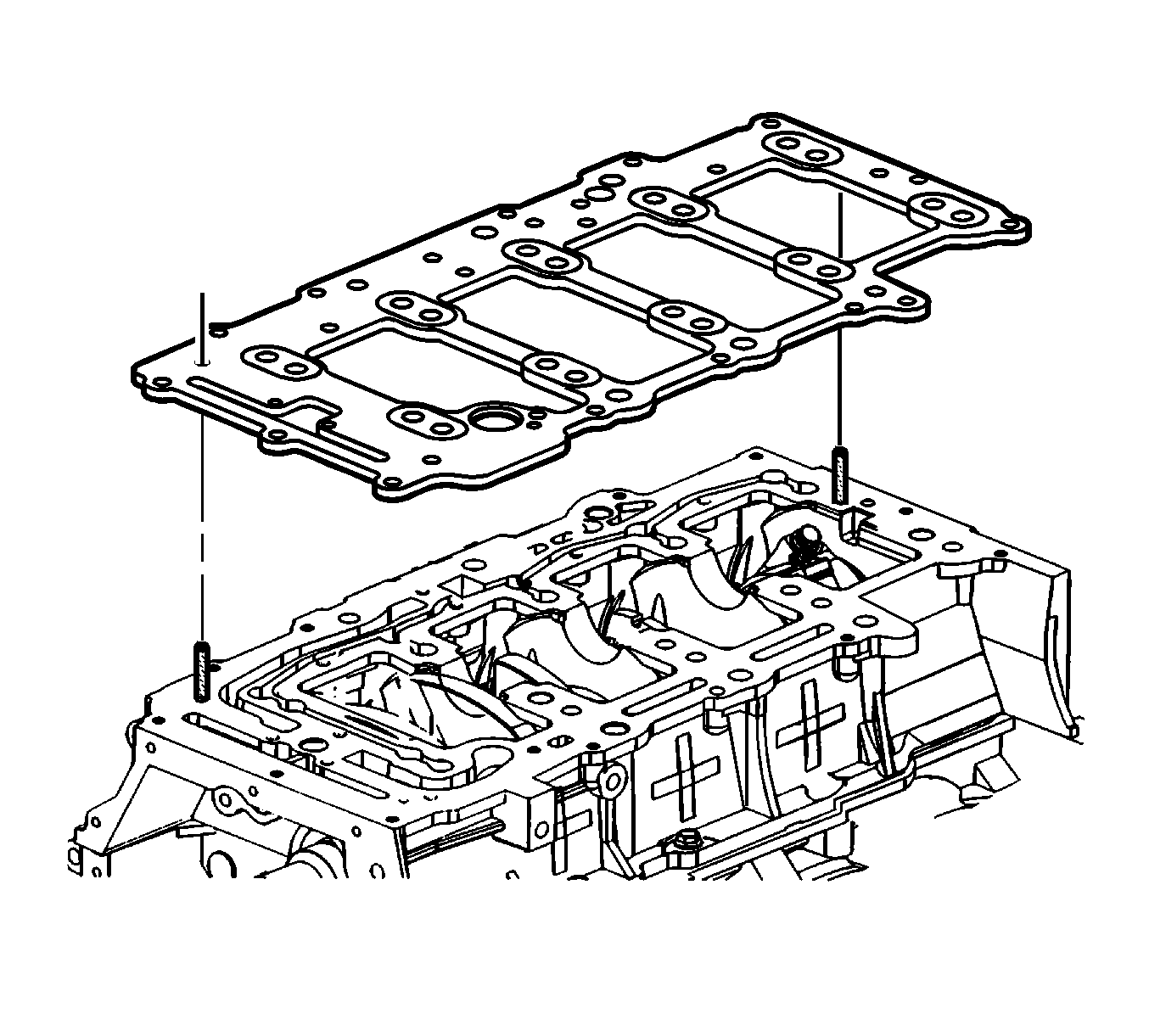
- Install the NEW oil distribution plate.
- Remove both of the EN 46109 tools.
- Install the oil distribution plate bolts.
Tighten
Tighten the oil distribution plate bolts to 10 N·m (89 lb in).
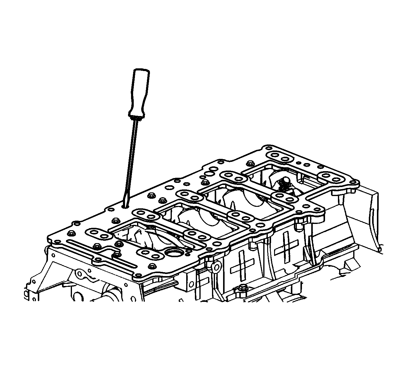
- Using a small long blade screwdriver, clean out any sealant in the oil drain back passages.
- Install the crankshaft oil scraper plate.
- Install the main bearing bolts. Ensure the stud-head bolts used for the oil suction tube support bracket are placed in the proper position.
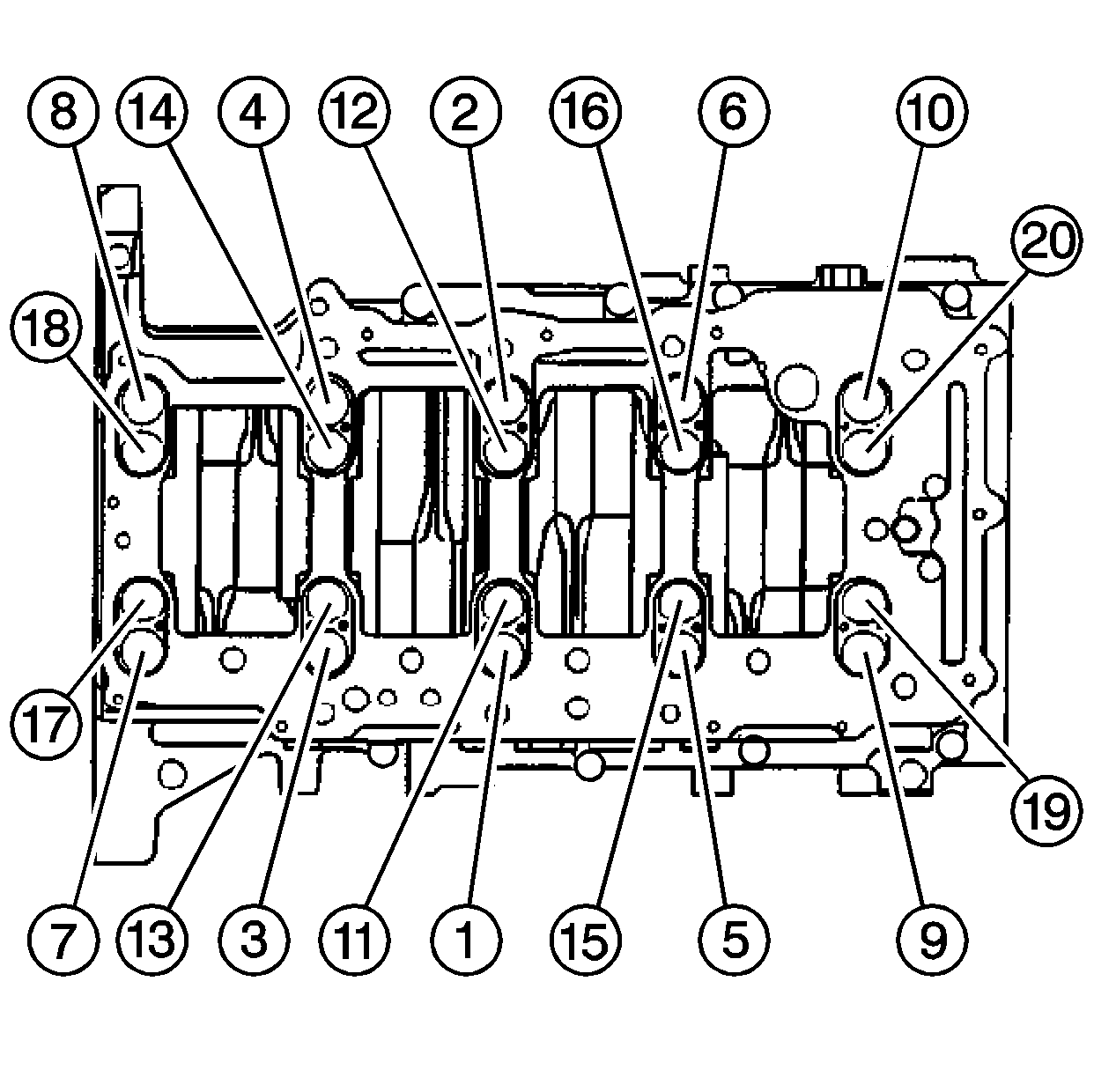
- Tighten the main bearing bolts in the proper sequence.
Tighten
Tighten the main bearing bolts (1 through 20) to 20 N·m (15 lb ft) in proper sequence.
Tighten
Tighten the main bearing bolts (1 through 20) an additional 65 degrees in proper sequence using the J 45059.
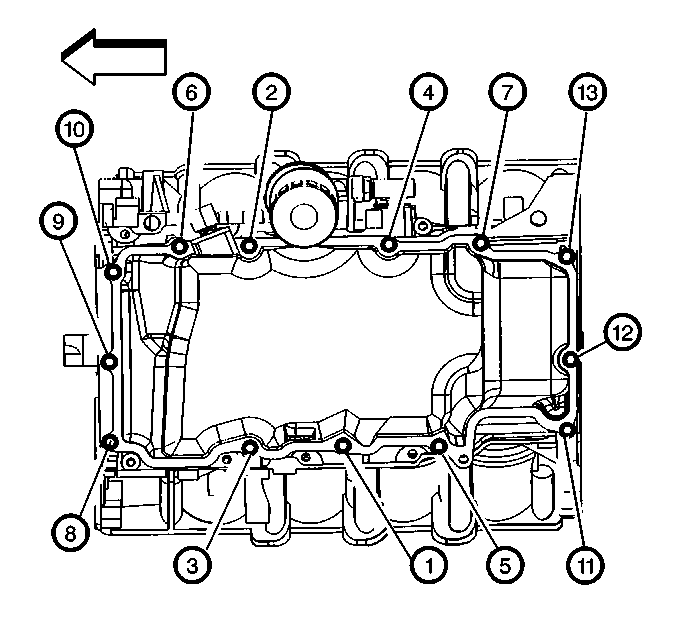
- Tighten the crankcase perimeter bolts in the sequence shown.
Tighten
Tighten the crankcase perimeter bolts to 30 N·m (22 lb ft).
- Using a small long bladed screwdriver, verify that the oil drain back passages are clear of sealant.
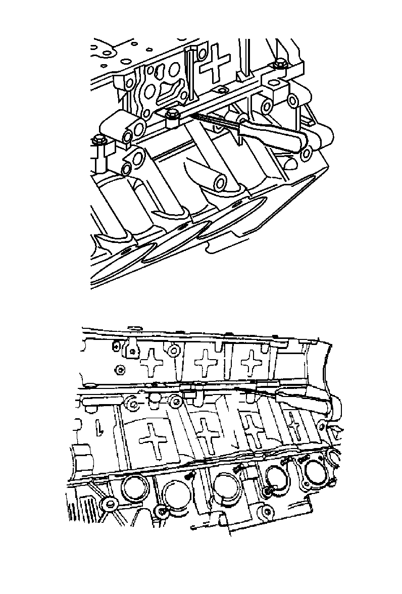
- Lubricate the silicone seal in the oil distribution plate. With a twisting motion, install the end of the oil suction tube (2).
- Install the oil suction tube retaining bolt (1) and nut (3).
Tighten
| • | Tighten the oil suction tube support bracket nut to 24 N·m (18 lb ft). |
| • | Tighten the oil suction tube bolt to 10 N·m (89 lb in). |
- Using a suitable cleaning solvent, clean the sealing surfaces and seal groove of the oil pan.
- Using a suitable cleaning solvent, clean the sealing surfaces of the oil distribution plate.
- Completely fill and slightly overfill the oil pan seal groove with a continuous bead of RTV sealant, P/N 12378521 (in Canada, use P/N 88901148) or P/N 88861417 (in Canada, use 88861418).
- Ensure the RTV sealant, P/N 12378521 (in Canada, use P/N 88901148) or P/N 88861417 (in Canada, use 88861418), bead is higher than the oil pan sealing surface by 3 mm (0.118 in).
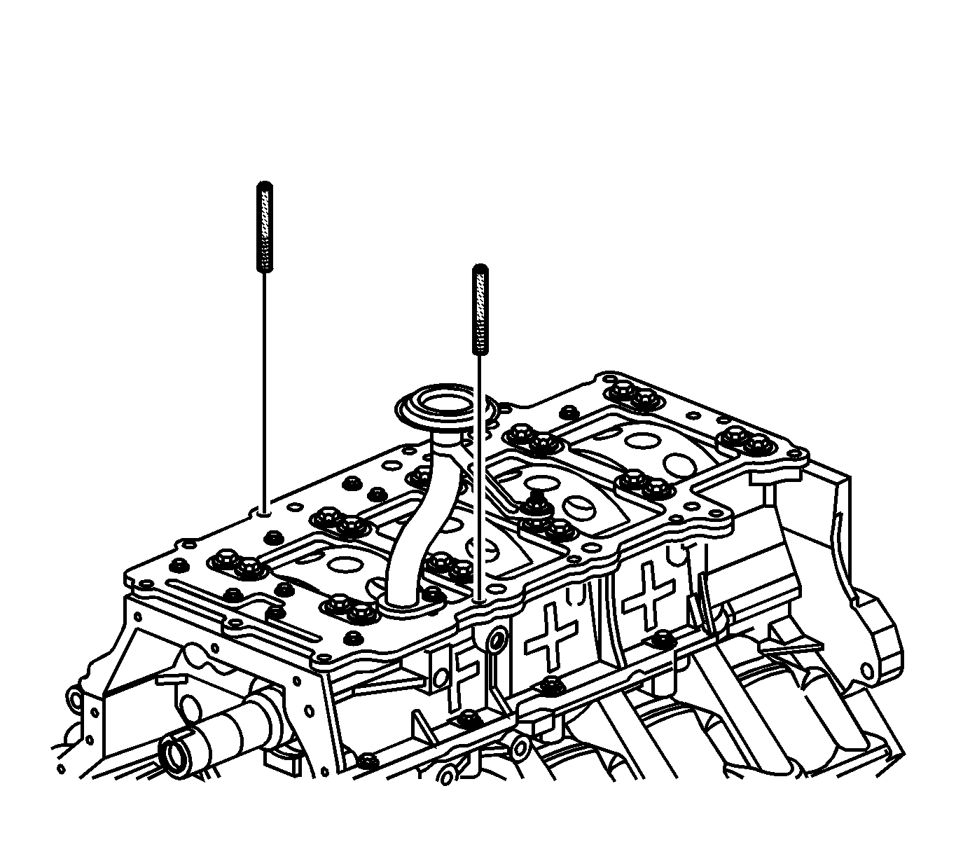
- To prevent shifting of the oil pan, install one of the EN 46109 tools into a bolt hole in each side of the lower crankcase.
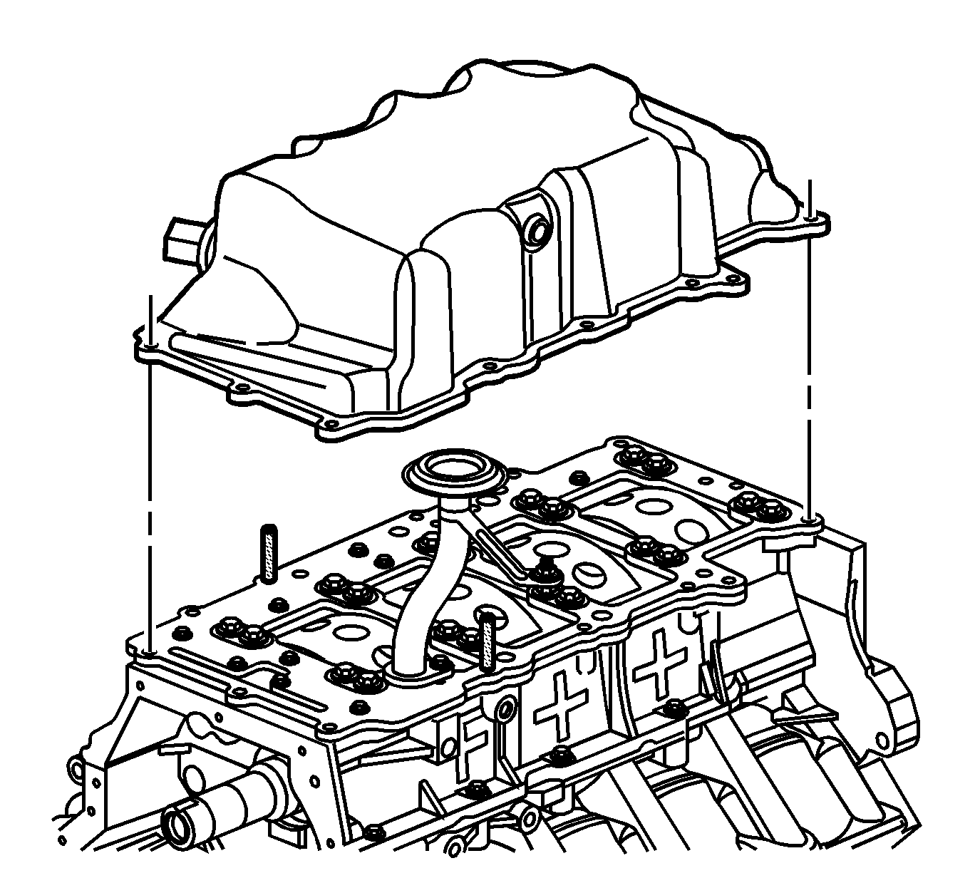
- Position the oil pan onto the lower crankcase.
- Remove both EN 46109 tools.
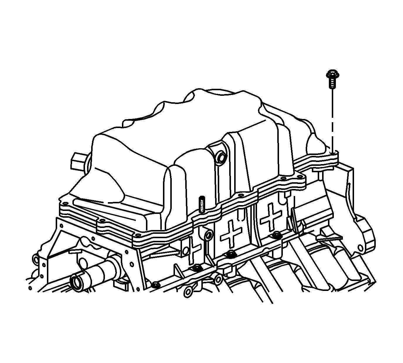
- Install the oil pan bolts.
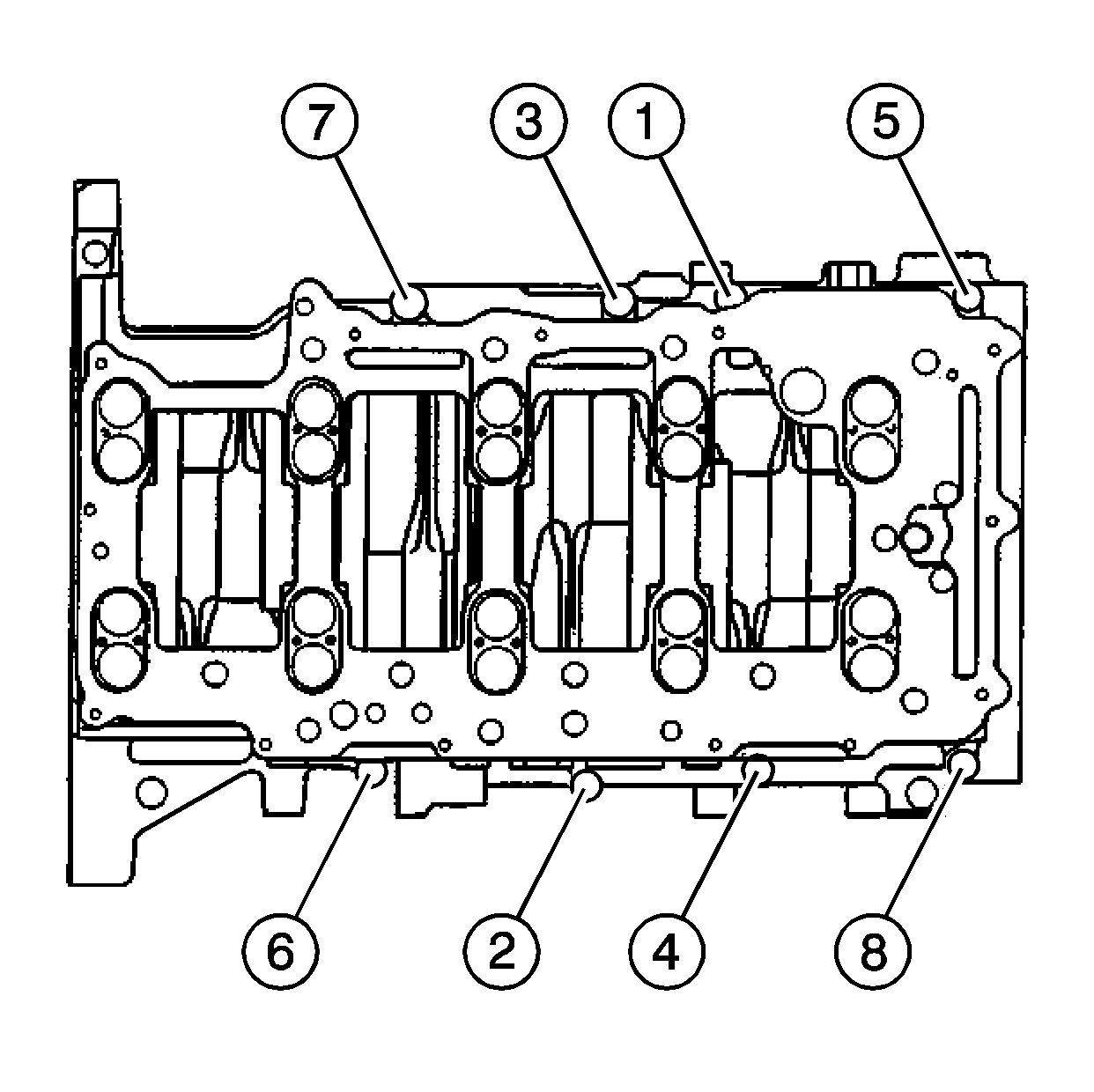
- Tighten the oil pan bolts in the sequence shown.
Tighten
Tighten the oil pan bolts in sequence to 10 N·m (89 lb in).
- Clean off any sealant that has protruded to the exterior of the engine.
Important:
| • | Ensure components being sealed with RTV sealant are assembled within 20 minutes. Components assembled after the RTV sealant has skinned-over, approximately 20 minutes or longer, will not bond. |
| • | EN-48072 must be used to ensure even application of the sealant in the bore and to prevent blockage of the drain back hole. |
- Install the crankshaft rear oil seal. Refer to the Crankshaft Rear Oil Seal Installation procedure in SI.
Important: For detailed component and engine installation, refer to Engine Replacement Procedure in the Engine Mechanical subsection of the appropriate Service Manual or SI.
- Install the components removed.
- Remove the engine from the engine stand.
- Install the engine to the transmission.
- Install a NEW oil filter.
- Install the power steering pump.
- Install the A/C compressor.
- Install the drive belt.
- Install the powertrain into the vehicle.
- Refill the engine coolant and the engine oil.
Warranty Information
It is vital that the exact part(s) replaced during any warranty repair be returned when requested. These parts must be the specific ones associated with the repair order requested and must carry the proper date codes for the production run of the vehicle
or component. Substitute parts are not acceptable. This information is used during warranty part reviews and is tracked to determine possible problems with a specific production run. Below is an example of a typical date code found on an engine component.
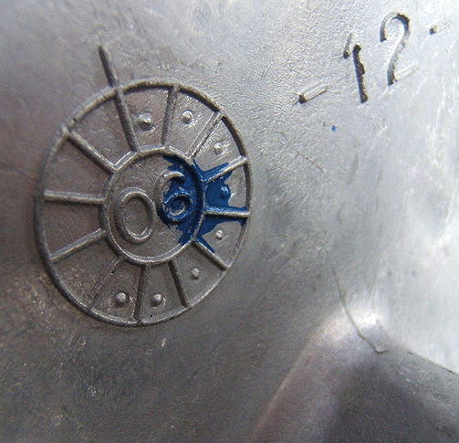
The more precisely that GM can isolate a production time frame that is causing customer concerns, the quicker and more effectively we can target a solution. For addition information on parts with date codes, please refer to GM Corporate Service Bulletin
#06-00-89-054B.
For vehicles repaired under warranty, use:
Labor Operation
| Description
| Labor Time
|
J1190
| Seal, Lower Crankcase - Replace
| Use Published Labor Time
|
