Removal Procedure
Notice:
• Use care when servicing the fuel system components, especially
the fuel injector electrical connectors, the fuel injector tips, and
the injector O-rings. Plug the inlet and the outlet ports of the fuel rail
in order to prevent contamination. • Do not use compressed air to clean the fuel rail assembly as this
may damage the fuel rail components. • Do not immerse the fuel rail assembly in a solvent bath in order
to prevent damage to the fuel rail assembly.
Notice: Cap the fittings and plug the holes when servicing the fuel system in order to prevent dirt and other contaminants from entering the open pipes and passages.
Important: When servicing the fuel rail, take precautions to prevent dirt and other contaminants from entering the fuel passages. Cap the fittings during servicing.
Important: Always maintain cleanliness when servicing fuel system components.
- Relieve the fuel system pressure. Refer to Fuel Pressure Relief .
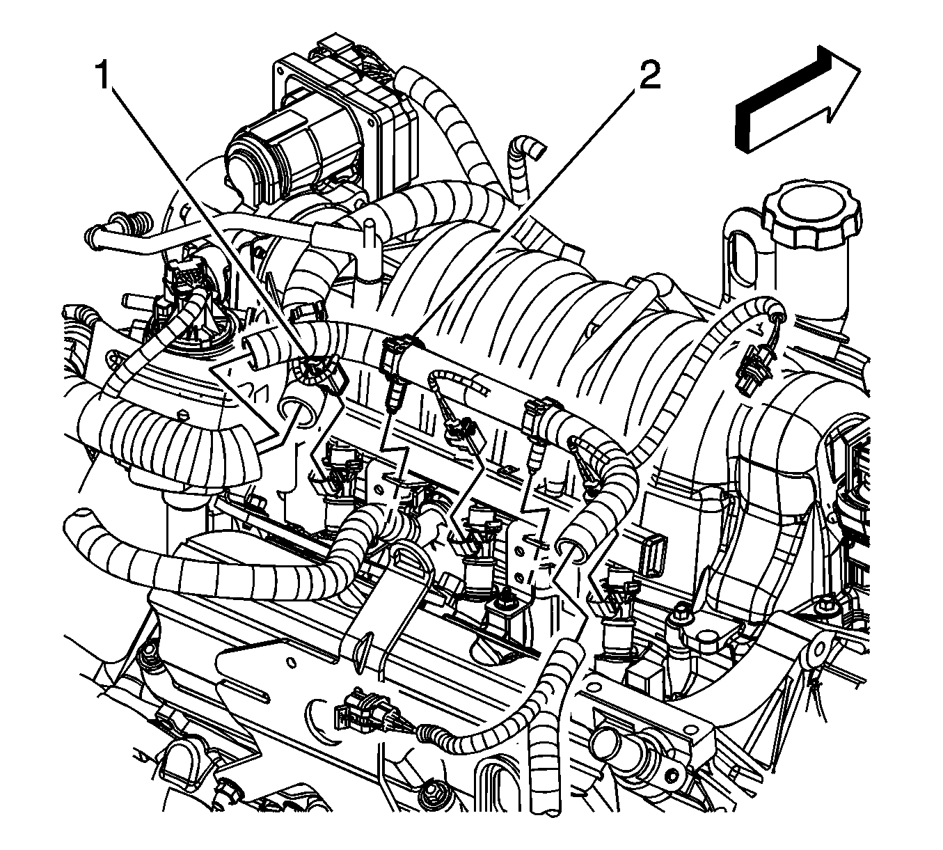
- Disconnect the fuel feed pipe (1) quick connect fitting at the fuel rail. Refer to Metal Collar Quick Connect Fitting Service .
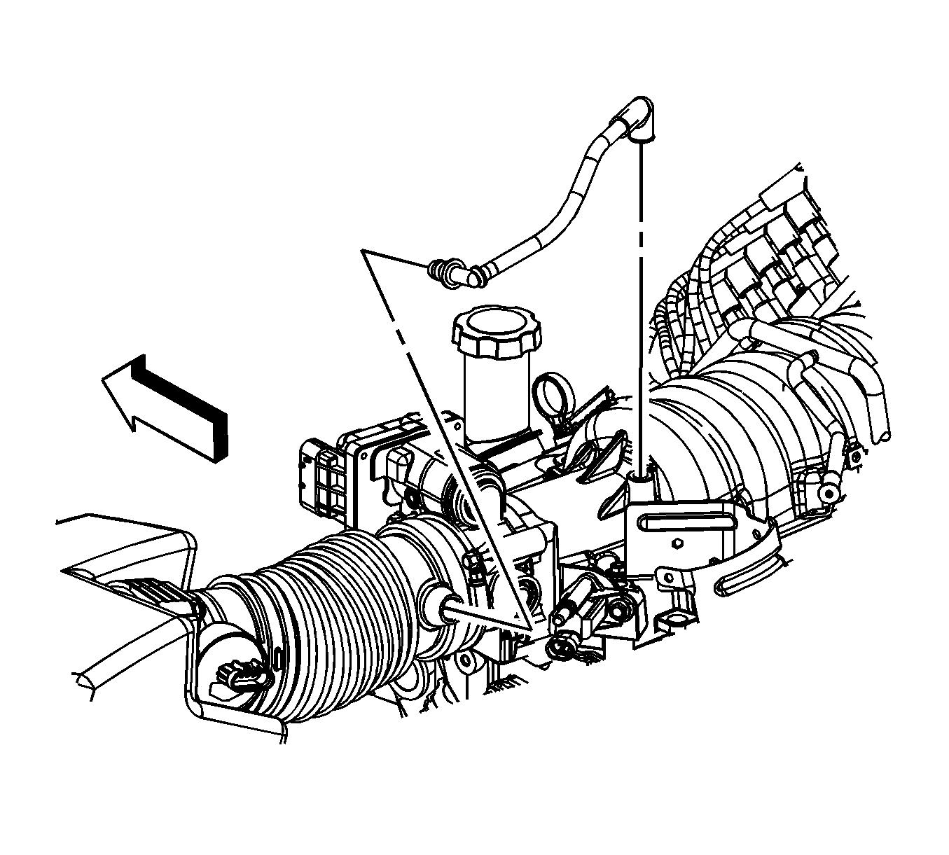
- Remove the positive crankcase ventilation (PCV) tube from the intake duct and intake manifold.
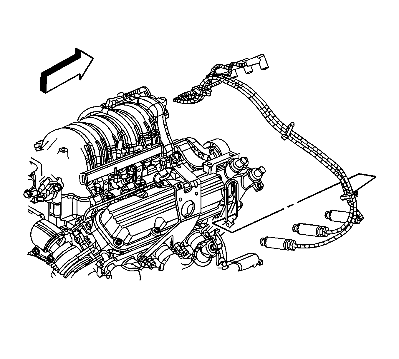
- Disconnect the spark plug wires from the ignition coils.
- Remove the spark plug wire retainer from the fuel rail.
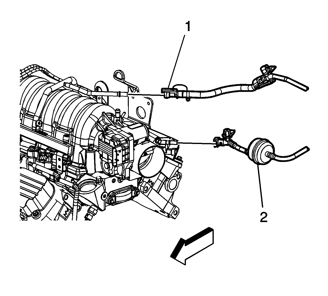
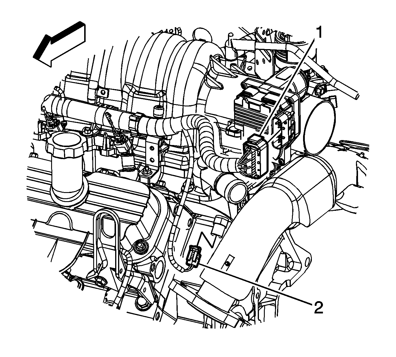
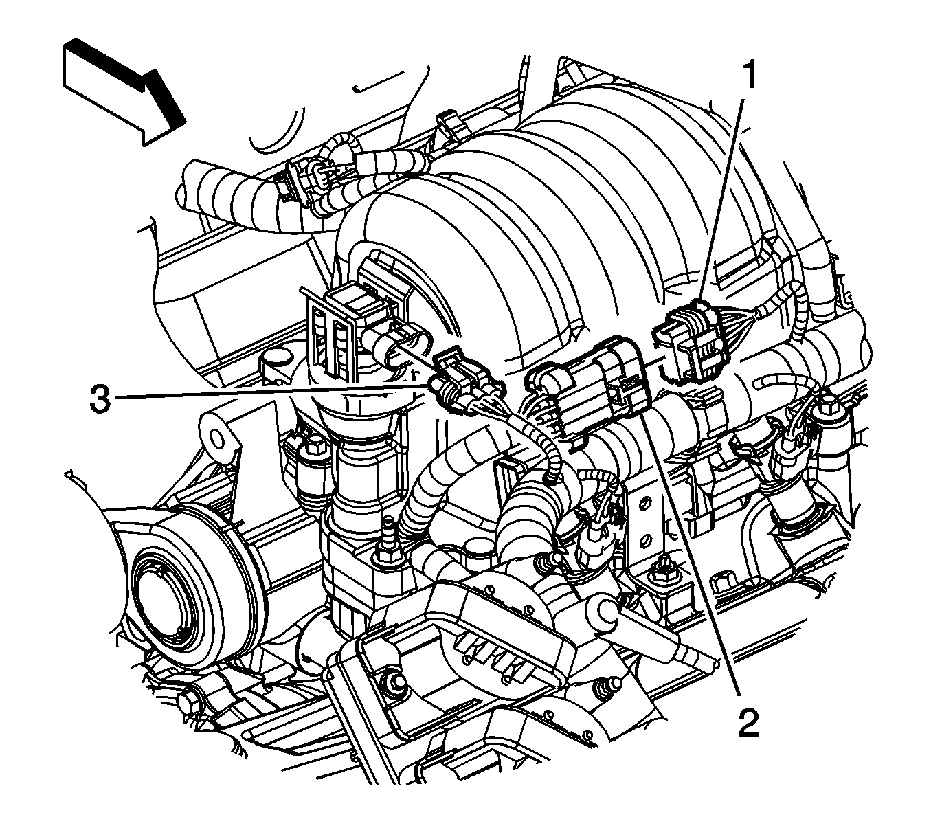
- Disconnect the engine harness electrical connector (1) from the throttle actuator.
- Disconnect the engine harness electrical connector (2) from the engine coolant temperature (ECT) sensor.
- Disconnect the engine harness electrical connector (1) from the ignition control module wiring harness electrical connector (2).
- Disconnect the engine harness electrical connector (3) from the manifold absolute pressure (MAP) sensor.
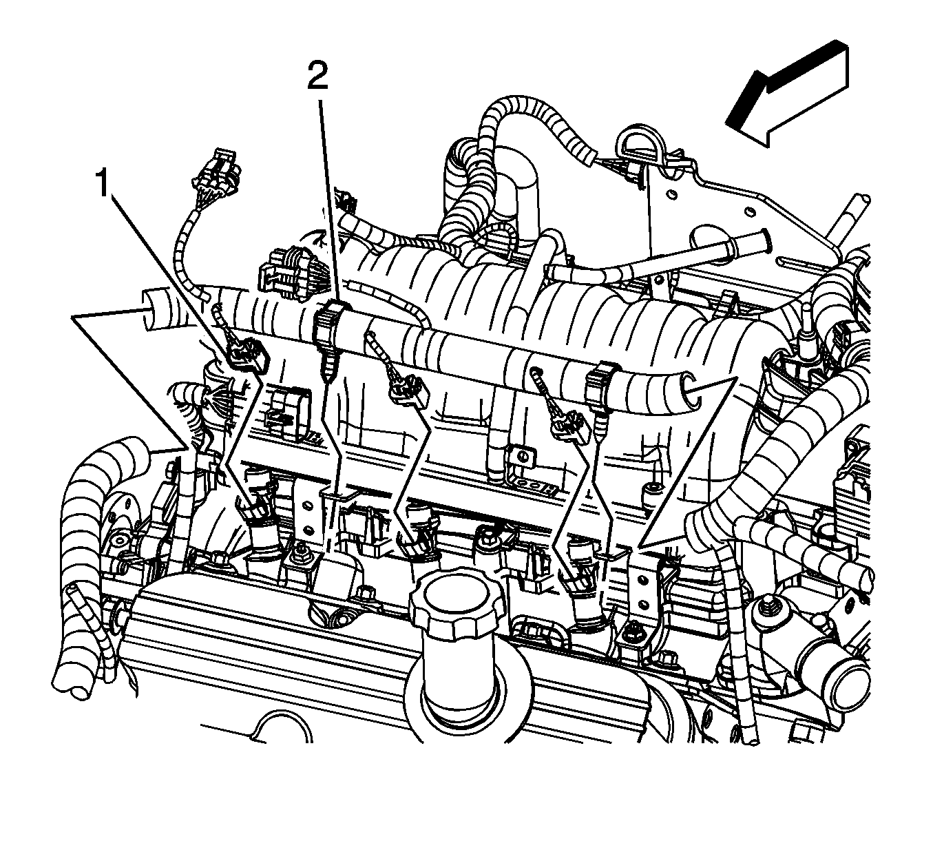
- Disconnect the front engine harness electrical connectors (1) from the fuel injectors.
- Remove the front engine harness retainers (2) from the fuel rail.
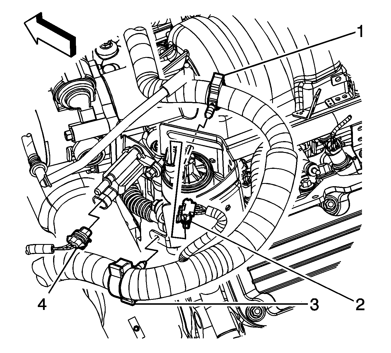
- Remove the engine harness retainers (1, 3) from the heat shield.
- Disconnect the engine harness electrical connector (2) from the exhaust gas recirculation (EGR) valve.
- Disconnect the engine harness electrical connector (4) from the evaporative emission (EVAP) solenoid.
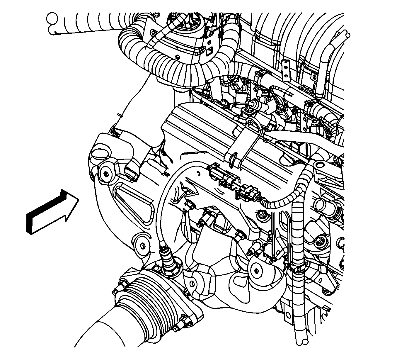
- Disconnect the engine harness electrical connector from the heated oxygen sensor (HO2S) pigtail.
- Disconnect the rear engine harness electrical connectors (1) from the fuel injectors.
- Remove the rear engine harness retainers (2) from the fuel rail.
- Gather the engine harness branches and reposition them out of the way.
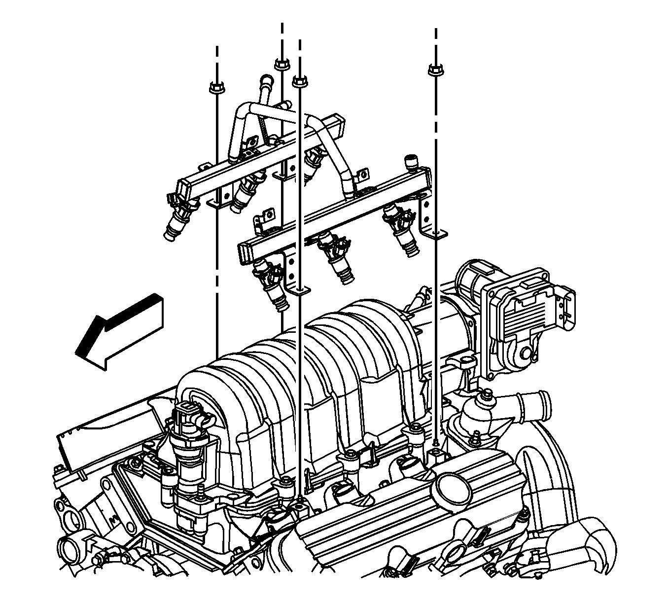
- Remove the fuel rail nuts.
- Gently lift the fuel rail up with equal force on both sides of the fuel rail.
- If replacing the fuel rail, perform the following steps otherwise proceed to step 6 in the installation procedure.
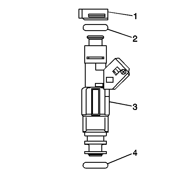
- Remove the fuel injector retainers (1).
- Remove the fuel injectors (3).
- Remove and discard the fuel injector upper O-ring seals (2).
- Remove and discard the fuel injector lower O-ring seals (4).
Installation Procedure
Caution: In order to reduce the risk of fire and personal injury that may result from a fuel leak, always install the fuel injector O-rings in the proper position. If the upper and lower O-rings are different colors (black and brown), be sure to install the black O-ring in the upper position and the brown O-ring in the lower position on the fuel injector. The O-rings are the same size but are made of different materials.
Notice:
• Use care when servicing the fuel system components, especially
the fuel injector electrical connectors, the fuel injector tips, and
the injector O-rings. Plug the inlet and the outlet ports of the fuel rail
in order to prevent contamination. • Do not use compressed air to clean the fuel rail assembly as this
may damage the fuel rail components. • Do not immerse the fuel rail assembly in a solvent bath in order
to prevent damage to the fuel rail assembly.
- If replacing the fuel rail, perform the following steps otherwise proceed to step 6.
- Lubricate the NEW O-ring seals with clean engine oil.
- Install the NEW fuel injector upper and lower O-ring seals (2, 4) onto the injectors.
- Install the fuel injectors (3).
- Install the fuel injector retainers (1).
- Lubricate the lower fuel injector O-ring seals with clean engine oil.
- Place the fuel rain into position and seat the fuel injectors by gently pressing down over the injectors.
- Install the fuel rail nuts.
- Position the engine harness over the engine.
- Install the engine harness retainers (2) to the fuel rail.
- Connect the engine harness electrical connectors (1) to the fuel injectors.
- Connect the engine harness electrical connector to the HO2S pigtail.
- Install the engine harness retainers (1, 3) to the heat shield.
- Connect the engine harness electrical connector (2) to the EGR valve.
- Connect the engine harness electrical connector (4) to the EVAP solenoid.
- Install the engine harness retainers (2) to the fuel rail.
- Connect the engine harness electrical connectors (1) to the fuel injectors.
- Connect the engine harness electrical connector (3) to the MAP sensor.
- Connect the engine harness electrical connector (1) to the ignition control module wiring harness electrical connector (2).
- Connect the engine harness electrical connector (2) to the ECT sensor.
- Connect the engine harness electrical connector (1) to the throttle actuator.
- Install the spark plug wire retainer to the fuel rail.
- Connect the spark plug wires to the ignition coils.
- Install the PCV tube to the intake duct and intake manifold.
- Connect the fuel feed pipe (1) quick connect fitting at the fuel rail. Refer to Metal Collar Quick Connect Fitting Service .
- Connect the negative battery cable. Refer to Battery Negative Cable Disconnection and Connection .
- Inspect for leaks.
- Install the intake manifold cover. Refer to Intake Manifold Cover Replacement .


Notice: Refer to Fastener Notice in the Preface section.
Tighten
Tighten the nuts to 10 N·m (89 lb in).


| 27.1. | Turn ON the ignition for 2 seconds. |
| 27.2. | Then OFF the ignition for 10 seconds. |
| 27.3. | Turn ON the ignition. |
| 27.4. | Inspect for fuel leaks. |
