Special Tools
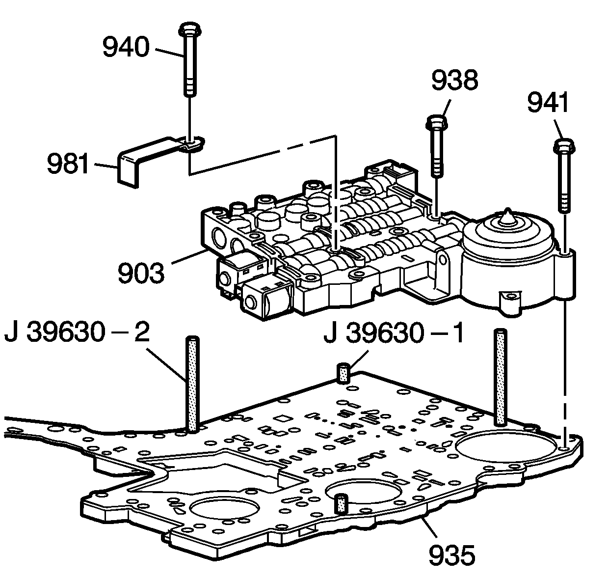
| • | J 39630-1 Lower Control/Valve Body Gasket Guide Pins |
| • | J 39630-2 Lower Control/Valve Body Gasket Guide Pins |
| • | DT-47707-R1 Internal Mode Switch Alignment Tool |
For equivalent regional tools, refer to
Special Tools.

- Install the lower control valve body (903) over the
J 39630-2 guide pins
.
Caution: Refer to Fastener Caution in the Preface section.
- Position the solenoid valve fluid filter retainer (981) onto the lower control valve body (903) and install some of the valve body bolts (938, 940, 941) and hand tighten them.
- Remove the
J 39630-2 guide pins
and tighten the bolts (938, 940, 941) in a star pattern to
8-14 N·m (6-10 lb ft).

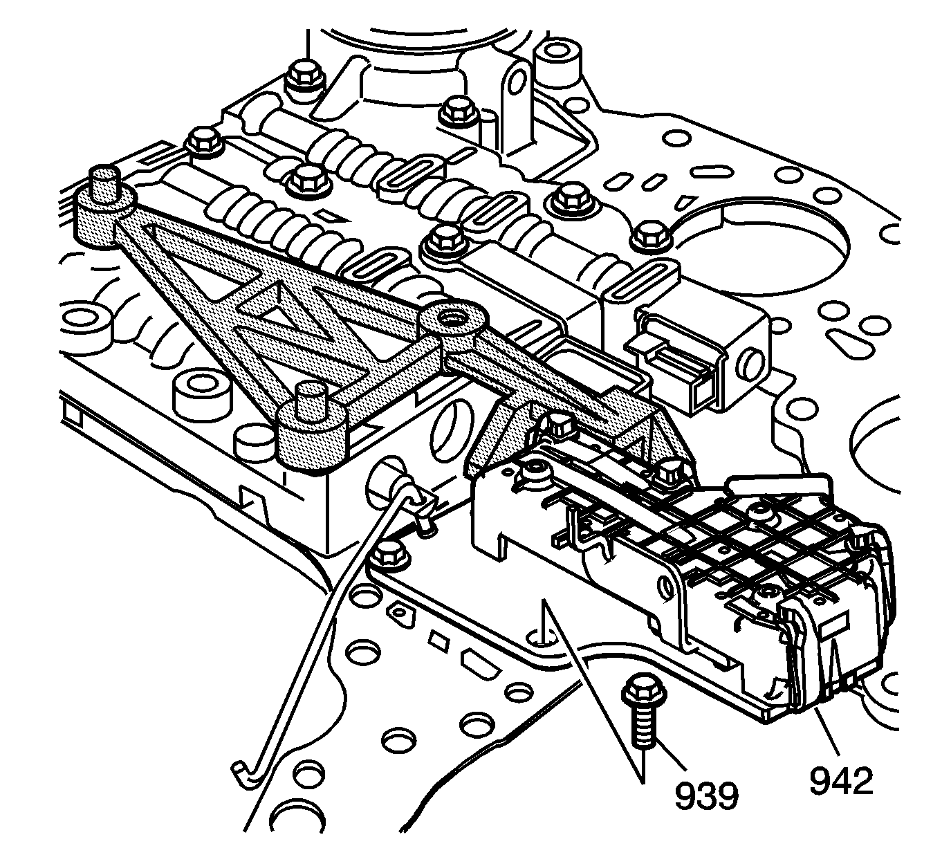
- Position the
DT-47707-R1 alignment tool
onto the lower control valve body, next to the 2-3 shift solenoid valve, and install the two
J 39630-1 guide pins
.
Note: Hold the IMS (942) against the
DT-47707-R1 alignment tool
while tightening the bolts.
- Locate the internal mode switch (IMS) (942) against the
DT-47707-R1 alignment tool
, install the three 8 mm bolts (939) and tighten to
8-14 N·m
(6-10 lb ft).
- Remove the
DT-47707-R1 alignment tool
and the
J 39630-1 guide pins
.

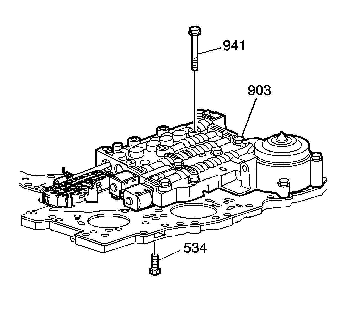
- Install the remaining bolts (941) into the lower
control valve body (903) and tighten to
8-14 N·m (6-19 lb ft).

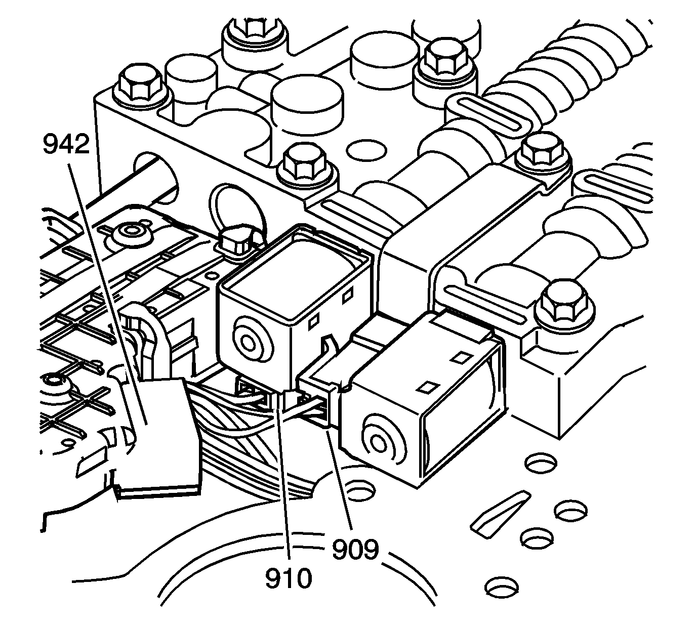
- Connect the lower control valve body wire harness (943) to the following
parts:
| • | 1-2 shift solenoid valve (909) |
| • | 2-3 shift solenoid valve (910) |
| • | Internal mode switch (IMS) (942) |


