GM Service Manual Online
For 1990-2009 cars only
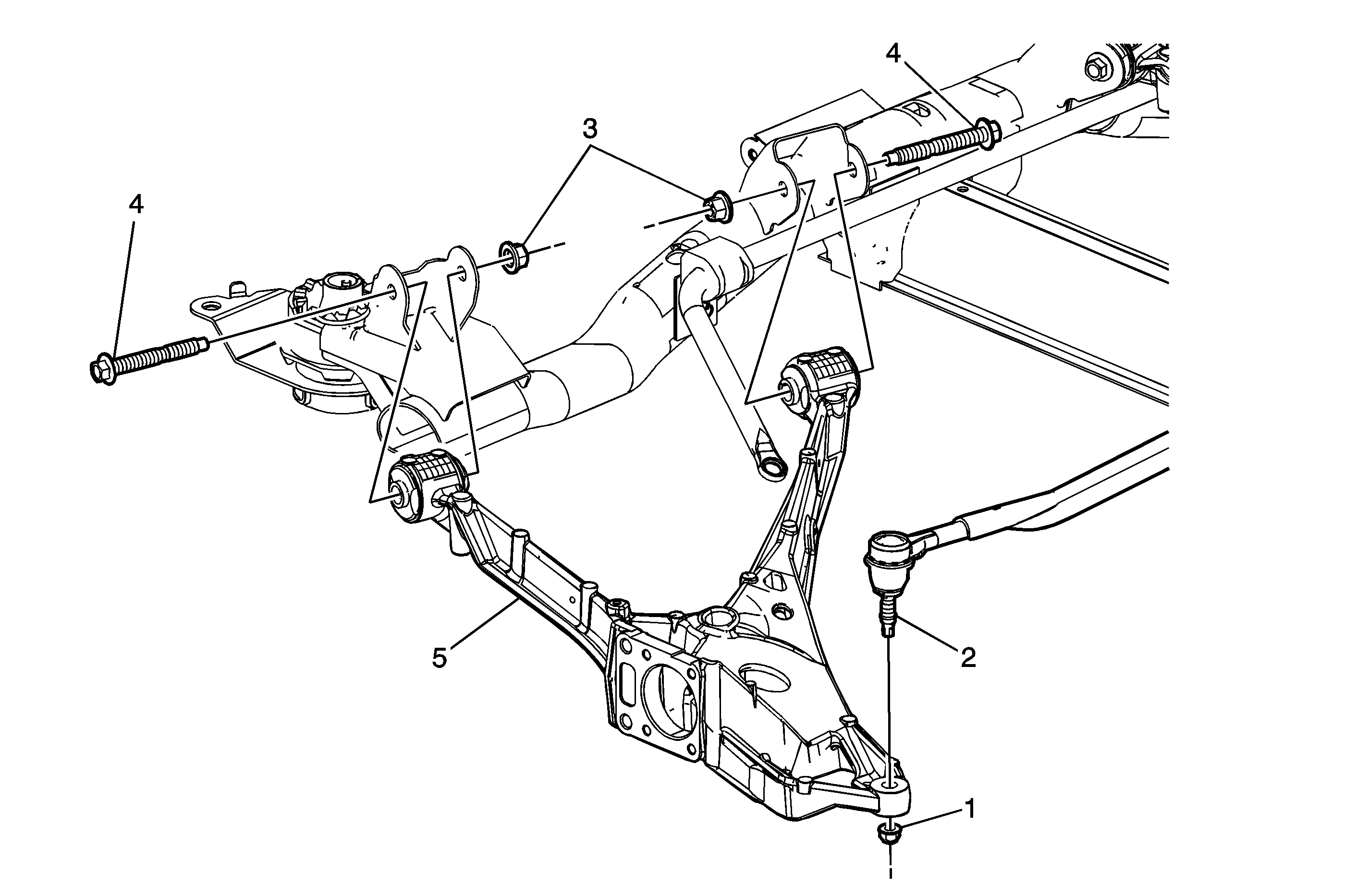
Object Number: 1664681  Size: MF

Callout

Component Name

Special Tools

J 24319-B Steering Linkage Puller

Preliminary Procedures

  1. Raise and support the vehicle. Refer to Lifting and Jacking the Vehicle.
  2. Remove the rear tire and wheel assembly. Refer to Tire and Wheel Removal and Installation.
  3. Remove the wheel bearing/hub. Refer to Rear Wheel Bearing and Hub Replacement.
  4. Remove the rear leveling sensor link from the control arm, if equipped. Refer to Automatic Level Control Sensor Replacement.
  5. Remove the stabilizer shaft link. Refer to Stabilizer Shaft Link Replacement.
  6. Remove the rear suspension support. Refer to Rear Support Replacement.

1

Rear Adjusting Link Nut

Caution: Refer to Fastener Caution in the Preface section.

Tighten
30 N·m (22 lb ft) plus an additional 180 degrees

2

Rear Adjusting Link

Tip
Use the J 24319-B to remove the adjusting link from the control arm.

3

Rear Control Arm Nut (Qty: 2)

Tighten
91 N·m (267 lb ft).

4

Rear Control Arm Bolt (Qty: 2)

Tip
Support the control arm before removing the bolts.

5

Rear Control Arm