For 1990-2009 cars only
Power Vacuum Brake Booster Replacement 3.9L
Removal Procedure
- Remove the intake manifold cover. Refer to Intake Manifold Cover Replacement.
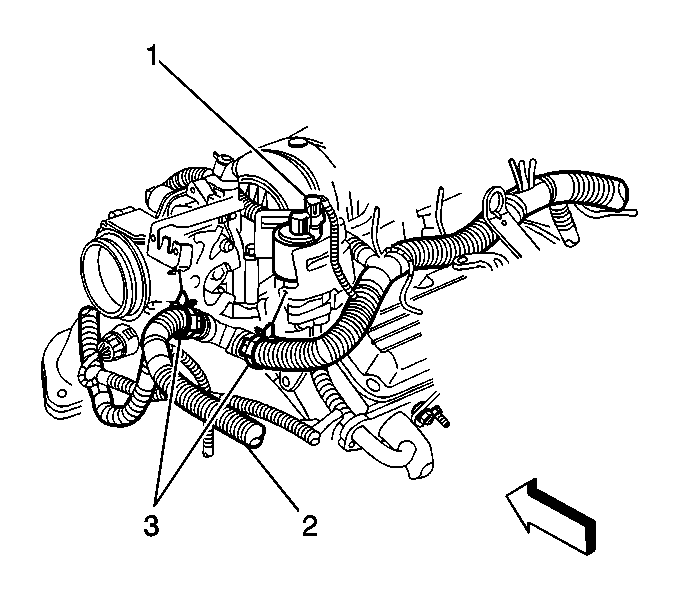
- Disconnect the electrical connector from the exhaust gas recirculation (EGR) valve (1).
- Disconnect the engine harness clips (3).
- Position the harness to the side.
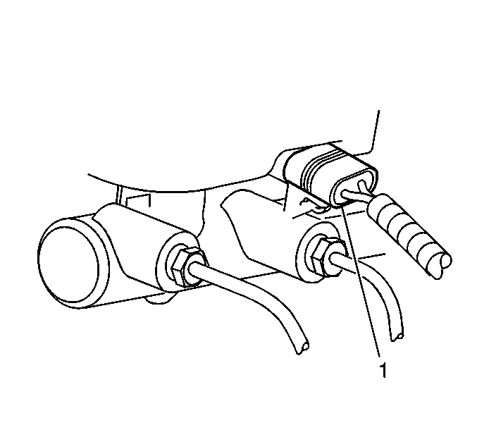
- Disconnect the brake fluid level indicator switch electrical connector (1).
- Remove the master cylinder nuts.
- Remove the master cylinder.
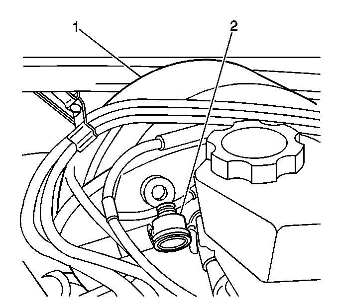
- Disconnect the power vacuum brake booster check valve and hose (2).
- Remove the left knee bolster. Refer to Driver Knee Bolster Replacement.
- Remove the steering column support mounting bolts. Refer to Steering Column Replacement.
- Lower the steering column and support with heavy mechanics wire.
- Disconnect the brake pedal position sensor electrical connector.
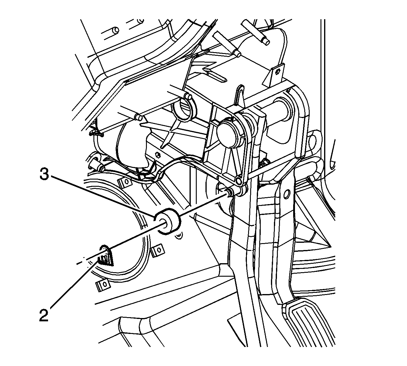
- Remove the bolt and the power vacuum brake booster pushrod retainer clip (2).
- Remove the vacuum brake booster pushrod spacer (3).
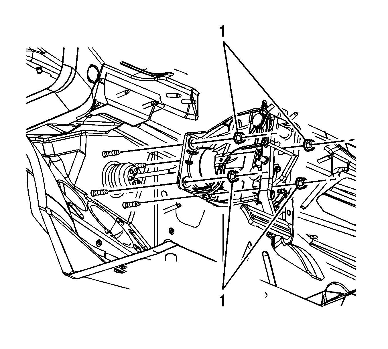
- Remove the power vacuum brake booster nuts (1).
- Remove the power vacuum brake booster.
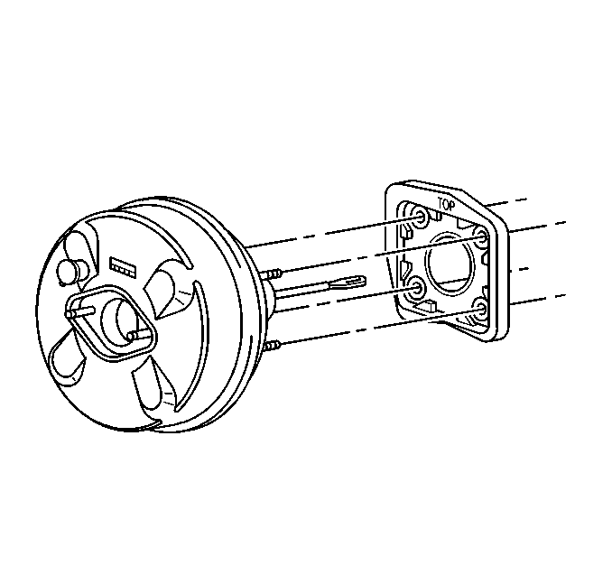
- Remove the power vacuum brake booster gasket.
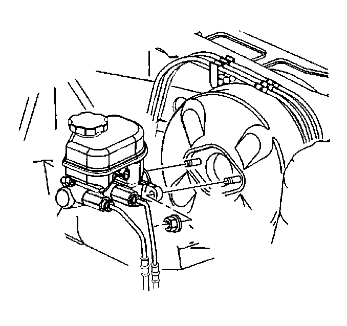
Position the master cylinder aside and support with heavy mechanics wire or equivalent.
Note: Do not reuse the power vacuum brake booster gasket if damaged.
Inspect the power vacuum brake booster for damage and replace, if necessary.
Installation Procedure
- Install the power vacuum brake booster gasket.
- Install the power vacuum brake booster.
- Install the power vacuum brake booster pushrod to the brake pedal.
- Install the spacer (3).
- Install the retaining clip (2).
- Install the power vacuum brake booster pushrod retaining clip bolt and tighten to 7 N·m (62 lb in)
- Install the power vacuum brake booster nuts (1) 30 N·m (22 lb ft).
- Connect the brake pedal position sensor electrical connector.
- Install the master cylinder. Refer to Master Cylinder Replacement.
- Install the steering column. Refer to Steering Column Replacement.
- Install the knee bolster panel. Refer to Driver Knee Bolster Replacement.
- Install the power vacuum brake booster check valve and hose (2).
- Install the brake fluid level indicator switch electrical connector (1).
- Position the engine wiring harness (2).
- Connect the electrical connector for the EGR valve (1).
- Connect the engine harness clips (3).
- Install the intake manifold cover. Refer to Intake Manifold Cover Replacement.
- Calibrate the brake pedal position sensor. Refer to Brake Pedal Position Sensor Calibration.


Caution: Refer to Fastener Caution in the Preface section.


Power Vacuum Brake Booster Replacement 4.6L
Removal Procedure
- Place the vehicle on a flat surface.
- Block the front wheels.
- Apply the parking brake.
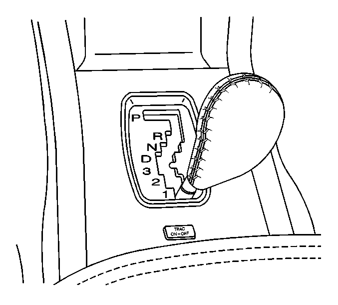
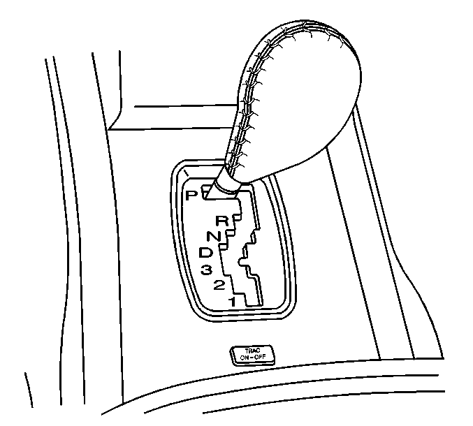
- To allow access for the removal of the vacuum brake booster, position the gearshift lever into the lowest gear.
- Remove the air cleaner assembly. Refer to Air Cleaner Assembly Replacement.
- Disconnect the fuel vapor lines in front of the brake booster.
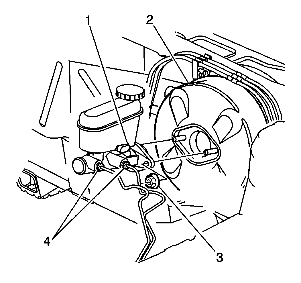
- Remove the master cylinder nuts (3).
- Disconnect the master cylinder (1) from the brake booster (2) and position forward.
- Disconnect the shift control cable from the shaft lever pin and position it out of the way. Refer to Automatic Transmission Range Selector Cable Replacement - Console.
- Disconnect the vacuum check valve (2) from the vacuum booster.
- Remove the left closeout insulator panel. Refer to Instrument Panel Insulator Panel Replacement - Left Side.
- Remove the left knee bolster. Refer to Driver Knee Bolster Replacement.
- To access the left lower brake pedal to vacuum brake booster mounting nut, remove the steering column mounting nuts. Refer to Steering Column Replacement.
- Lower the steering column and support with heavy mechanics wire or equivalent.
- Remove the power vacuum brake booster pushrod retaining clip (2) from the brake pedal.
- Remove the spacer (3).
- Disconnect the power vacuum brake booster pushrod from the brake pedal.
- Remove the power vacuum brake booster nuts (1).
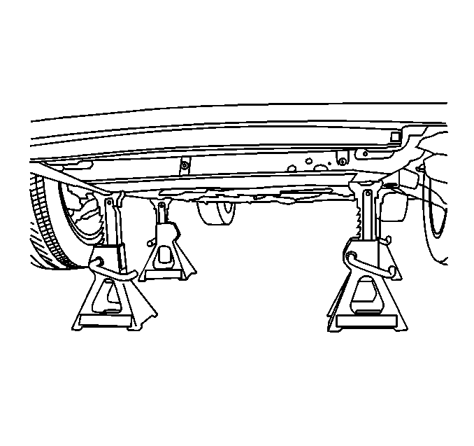
- Raise the vehicle. Refer to Lifting and Jacking the Vehicle.
- Support the front frame with jack stands.
- Loosen the left side frame bolts. Refer to Front Frame Replacement.
- Lower the left side frame 51-76 mm (2-3 in) to gain clearance to remove the brake booster. Refer to Front Frame Replacement.
- Remove the power vacuum brake booster from the vehicle.
- Remove the power vacuum brake booster gasket.
| • | For the lines that have the plastic connectors, refer to Plastic Collar Quick Connect Fitting Service. |
| • | For the lines that have the metal connectors, refer to Metal Collar Quick Connect Fitting Service. |
Note: Do not disconnect the brake pipes from the master cylinder.



Note: Do not reuse the power vacuum brake booster gasket if damaged.
Inspect the power vacuum brake booster gasket and replace, if necessary.
Installation Procedure
- Install the power vacuum brake booster gasket to the booster.
- Install the power vacuum brake booster to the vehicle.
- Install the front frame. Refer to Front Frame Replacement.
- Lower the vehicle.
- Install the power vacuum brake booster nuts (1) and tighten to 30 N·m (22 lb ft).
- Apply a small amount of silicone brake lubricant to the brake pedal pivot.
- Connect the power vacuum brake booster pushrod to the brake pedal.
- Install the spacer (3) to the brake pedal.
- Install the power vacuum brake booster pushrod retainer clip (2) to the brake pedal.
- Install the power vacuum brake booster pushrod retaining clip bolt and tighten to 7 N·m (62 lb in).
- Install the steering column. Refer to Steering Column Replacement.
- Install the left knee bolster. Refer to Driver Knee Bolster Replacement.
- Install the left insulator panel. Refer to Instrument Panel Insulator Panel Replacement - Left Side.
- Install the shift control cable to the shift cable bracket. Refer to Automatic Transmission Range Selector Cable Replacement - Console.
- Position the gearshift lever into park.
- Install the power vacuum brake booster check valve (2) to the brake booster.
- Install the master cylinder to the brake booster. Refer to Master Cylinder Replacement.
- Connect the fuel vapor lines in front of the brake booster.

Caution: Refer to Fastener Caution in the Preface section.



| • | For the lines that have the plastic connectors, refer to Plastic Collar Quick Connect Fitting Service. |
| • | For the lines that have the metal connectors, refer to Metal Collar Quick Connect Fitting Service. |
