Special Tools
J 39061 Converter Seal Installer
For equivalent regional tools, refer to
Special Tools.
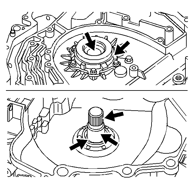
- Inspect the drive sprocket support for the following:
| • | Blocked converter drain holes |
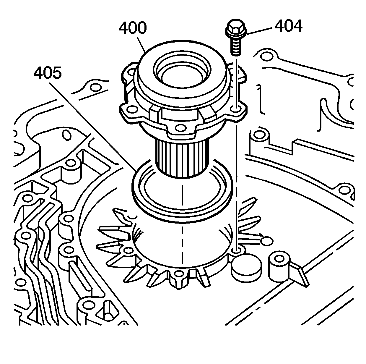
- Remove the six 8 mm drive sprocket support bolts (404).
- Remove the drive sprocket support (400) and the drive sprocket support seal (405).
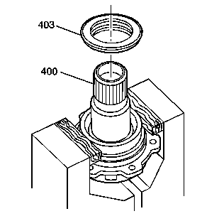
- Place the drive sprocket support (400) in a soft jaw vise. Use a wedge-shaped chisel in order to remove
the converter helix seal (403).

- Install a new drive sprocket support seal (405). Install the drive sprocket support (400) into the case.
Caution: Refer to Fastener Caution in the Preface section.
- Install the six 8 mm bolts (404) and using a star pattern, tighten the bolts to
11-13 N·m (8.0-9.5 lb ft).
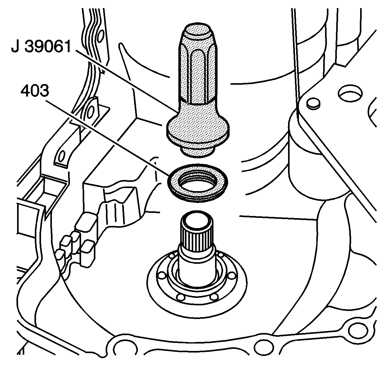
- Use the
J 39061 seal installer
in order to install the
new converter helix seal (403).
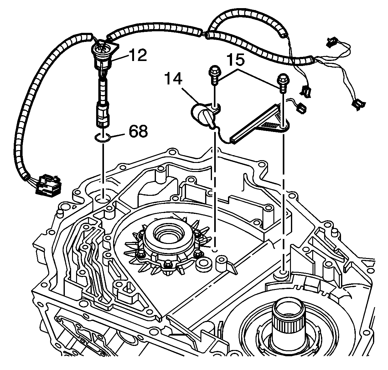
- Inspect the wiring harness (12) for the following:
| • | Bent or broken connectors |
- Install the wiring harness (12) into the case, with the notch going toward the inside of the case. Make sure that the harness snaps into place at the pass through connector (12). Insert the remainder of the harness into the valleys
of the case housing.
- Install the input speed sensor (14) and its bolt (15).
- Install the input speed sensor wire harness bracket to the center of the case. Install its bolt (15).
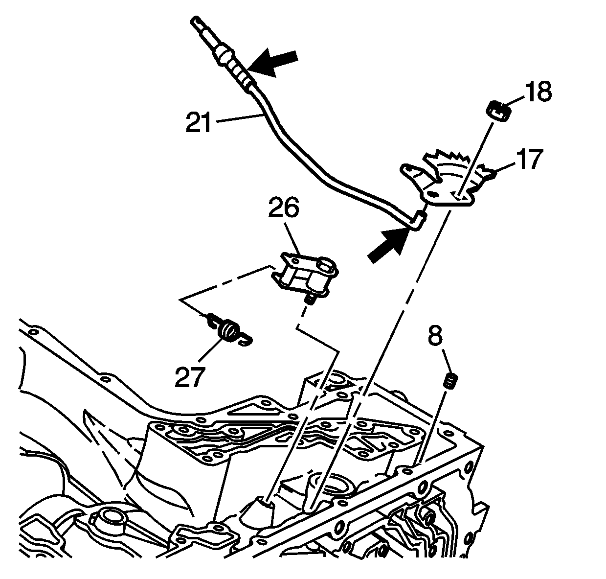
- Inspect the actuator park lock sleeve for excessive wear. Inspect the actuator rod (21) for a cracked end, a bent rod, or a broken spring.
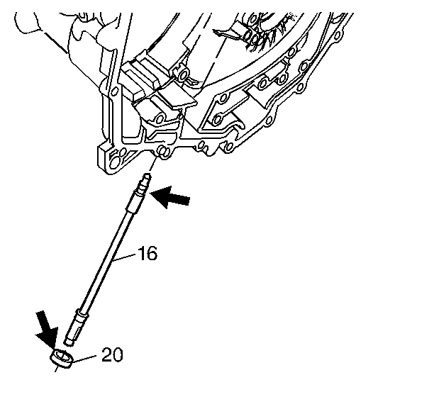
- Inspect the threads on the manual shaft (16). Inspect the machined area of the manual shaft (16), where the manual
shaft seal (20) rides, for nicks and burrs.
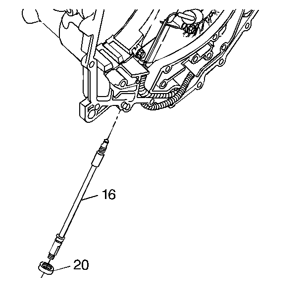
- Install the new manual shaft seal (20) onto the manual shaft (16).
- Place the manual shaft (16) through the case.
- Align the notch on the input speed sensor wire harness bracket to the groove on the manual shaft.
- Tighten bolt (15) to
11-13 N·m (8.0-9.5 lb ft) .
- Seat the manual shaft seal (20) with the appropriate socket.
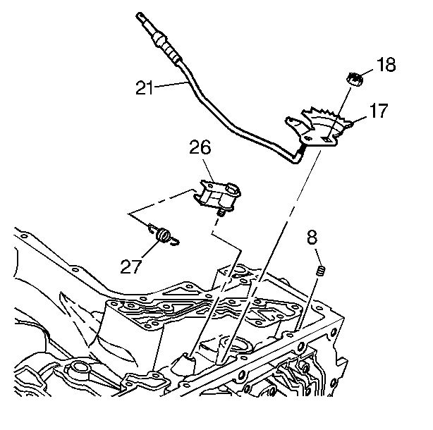
- Attach the new detent lever (17), the actuator rod (21) and the manual shaft nut (18)
to the manual shaft. Hold the detent lever (17) stationary with a screwdriver in order to prevent bending of the actuator rod (21). Slide the actuator rod (21) into the actuator park lock sleeve.
- Tighten the manual shaft nut (18) to
27-34 N·m (20-25 lb ft).
- Install the detent roller assembly washer (26), the pivot arm, and the sleeves. Start the pivot bolt by hand. Tighten the pivot bolt to
8-14 N·m (6-10 lb ft).
- Tighten the pivot bolt to
27-34 N·m (20-25 lb ft).
- Install the detent return spring (27) to the detent roller assembly (26) and to the manual shaft. Install the spring with the small hook end around of the top of the manual shaft.


