NEW TOOL FOR OPTICAL REDUNDANT STEERING WHEEL CONTROL SYSTEM

SUBJECT: INFORMATION ON NEW SERVICE TOOL AND ENHANCED DIAGNOSTICS FOR OPTICAL REDUNDANT STEERING WHEEL CONTROL SYSTEM
VEHICLES AFFECTED: 1989-93 "A,C,E,H,W" MODELS
MODELS AFFECTED:
1989-1993 Buick W, 1991-92 Buick A, 1989-90 Oldsmobile C, 1989 Oldsmobile E, 1993 Oldsmobile U, 1989-93 Oldsmobile W, 1989-91 Pontiac A, 1989-91 Pontiac H, 1993 Pontiac U, 1989-93 Pontiac W
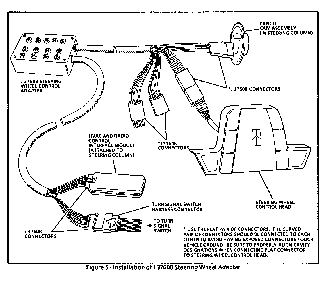
A new essential tool (J37608-92) was released in November of 1992 for, all Pontiac, Oldsmobile and Buick dealerships. The new tool consists of three individual jumper harnesses that work in conjunction with the Steering Wheel Control Adapter (J37608). The tools mentioned above are used in diagnosing Optical Steering Wheel Control (SWC) systems. They are not used for Analog SWC systems.
The purpose of the new tools is to allow for isolation of the different Optical SWC components. The purpose of each tool:
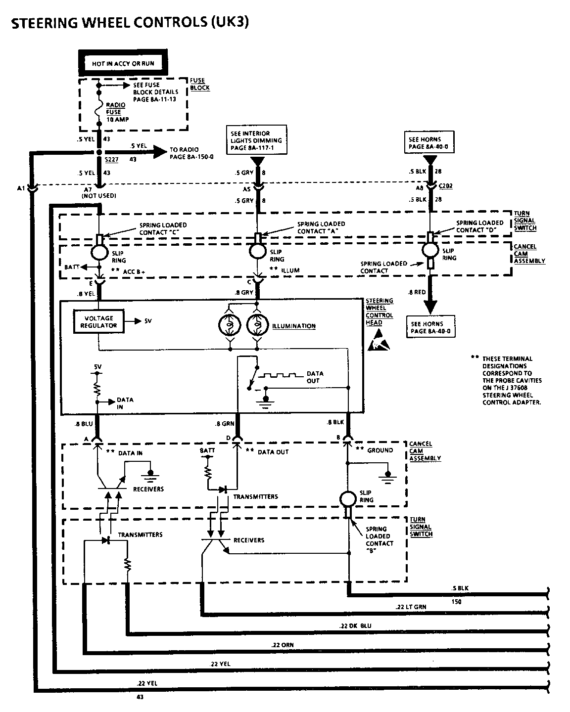
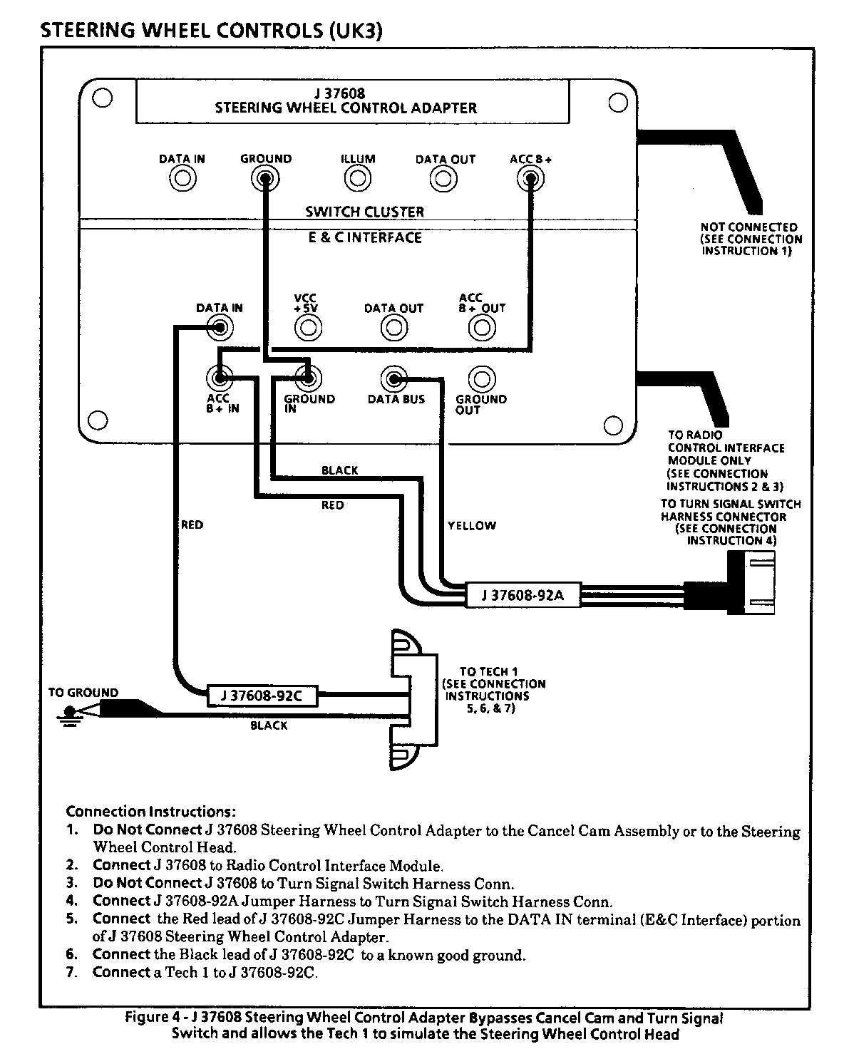
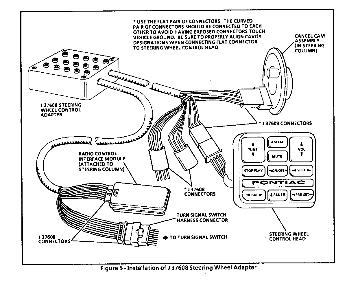
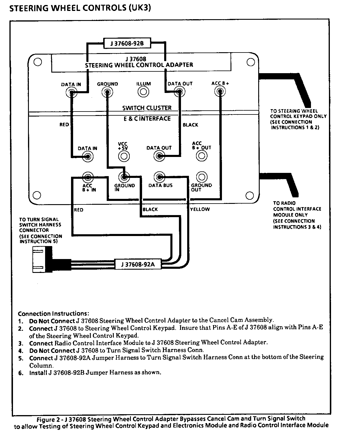
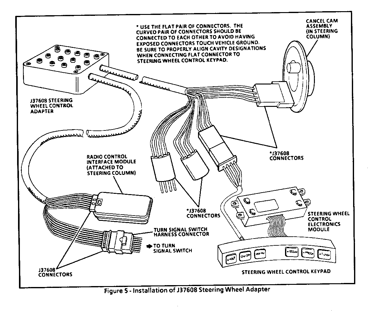
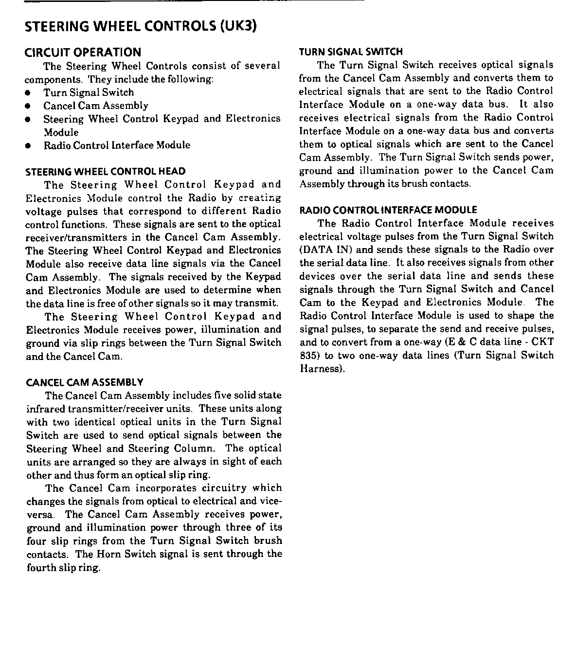
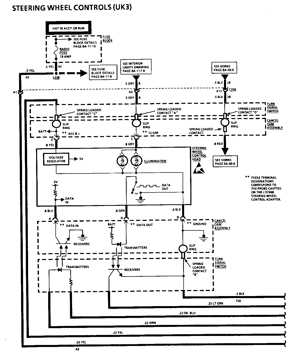
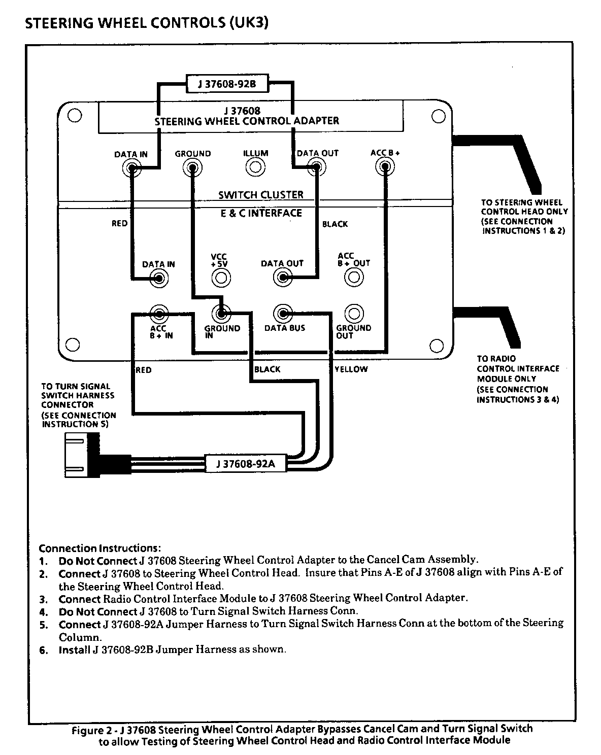
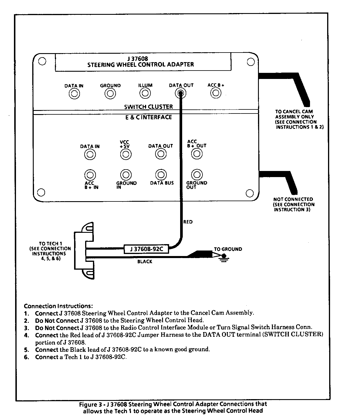
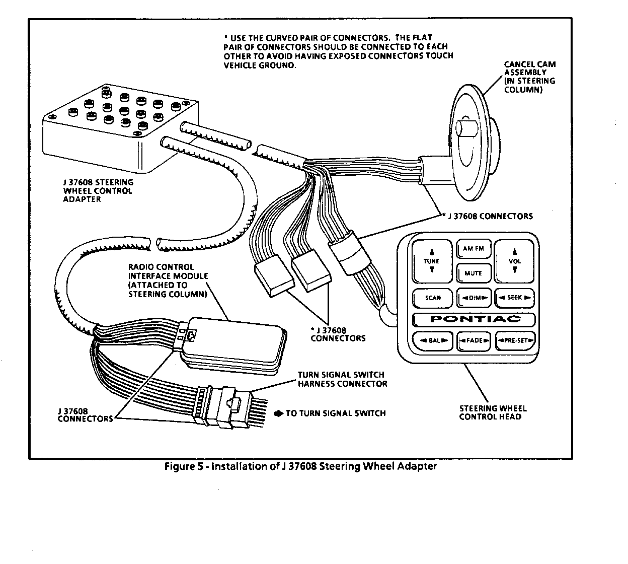
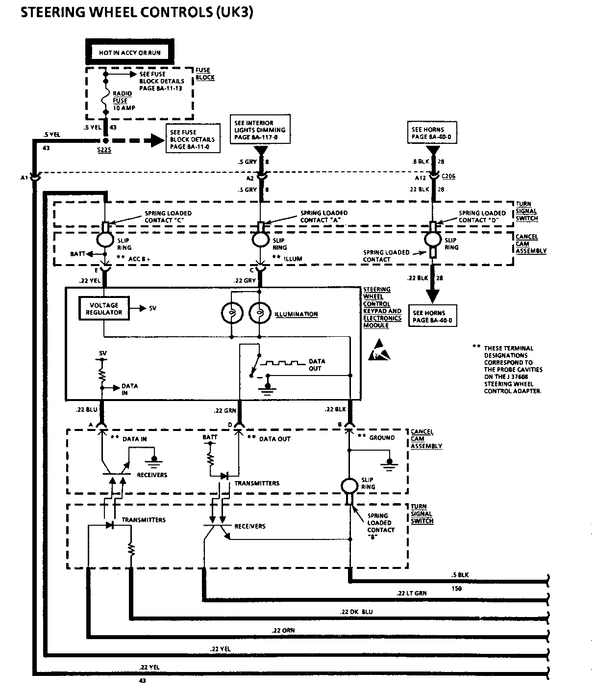
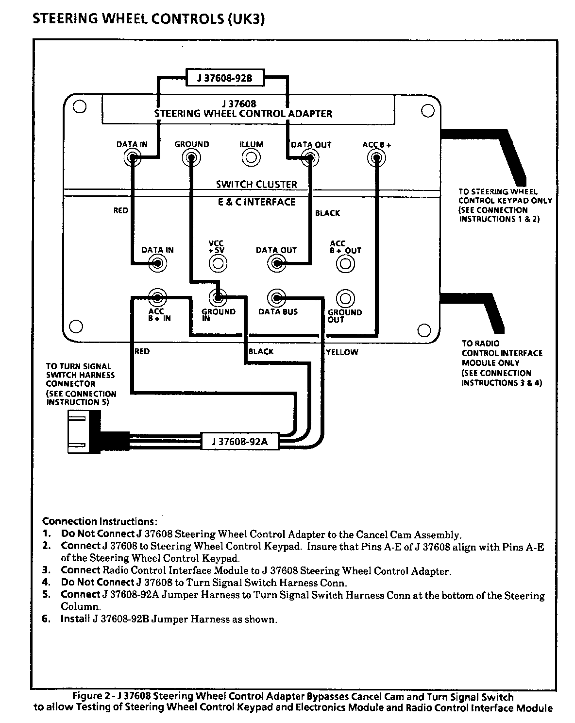
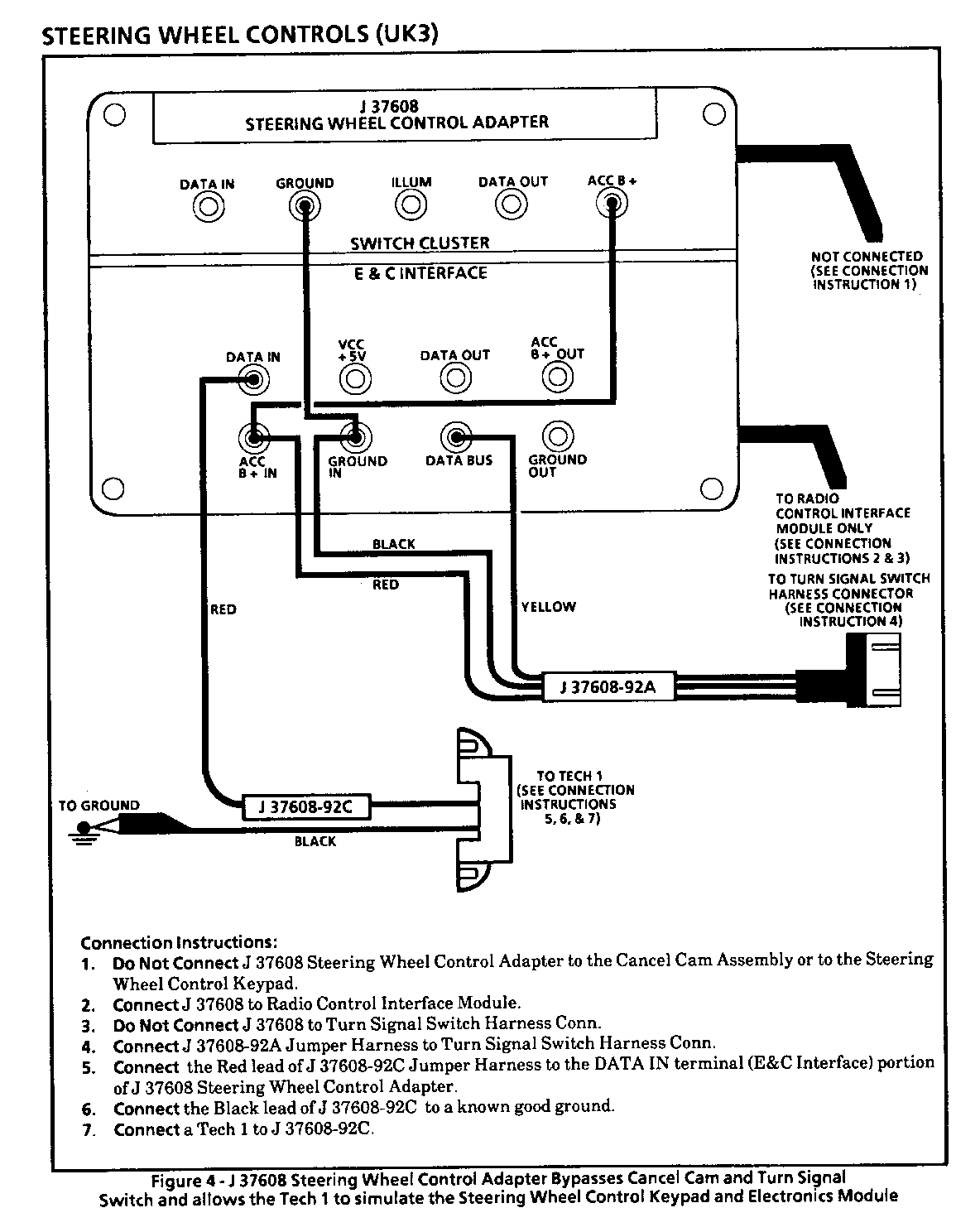
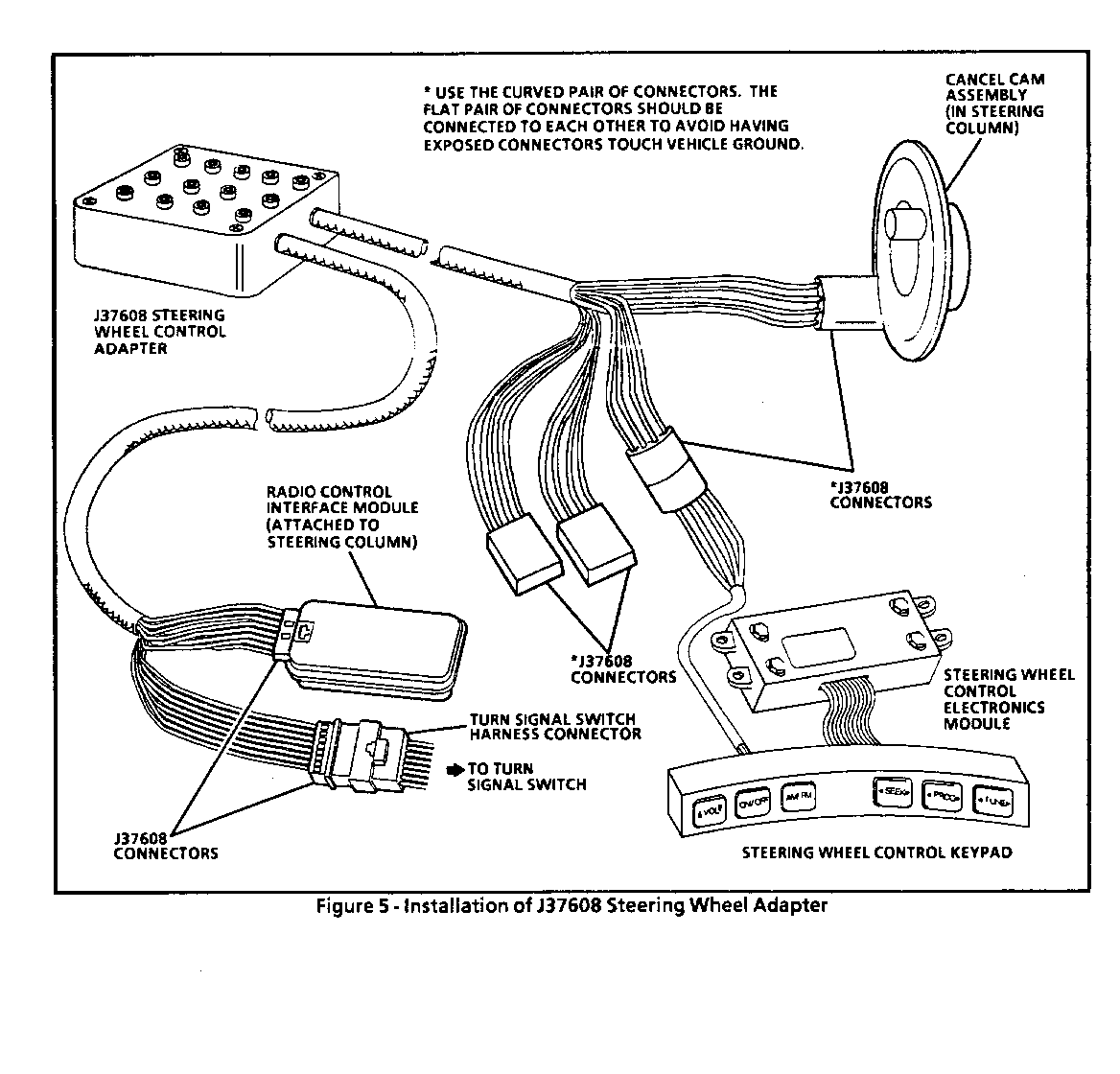
J37608 (Steering Wheel Control Adapter) - This tool can connect (to the cancel cam assembly, E & C Interface Module) in parallel to the Cancel Cam Assembly, the E & C Interface Module, the Tum Signal Switch, and the SWC head or keypad. It allows for voltage measurements to be taken on any of the SWC power, ground, illumination, or data lines.
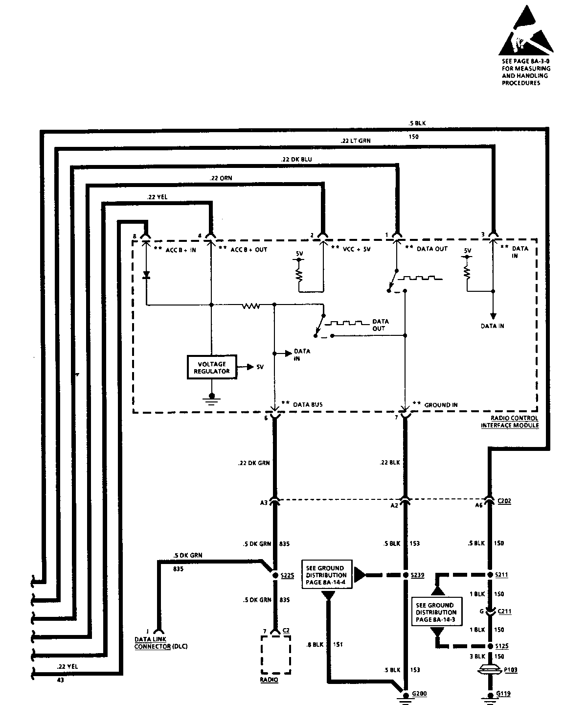
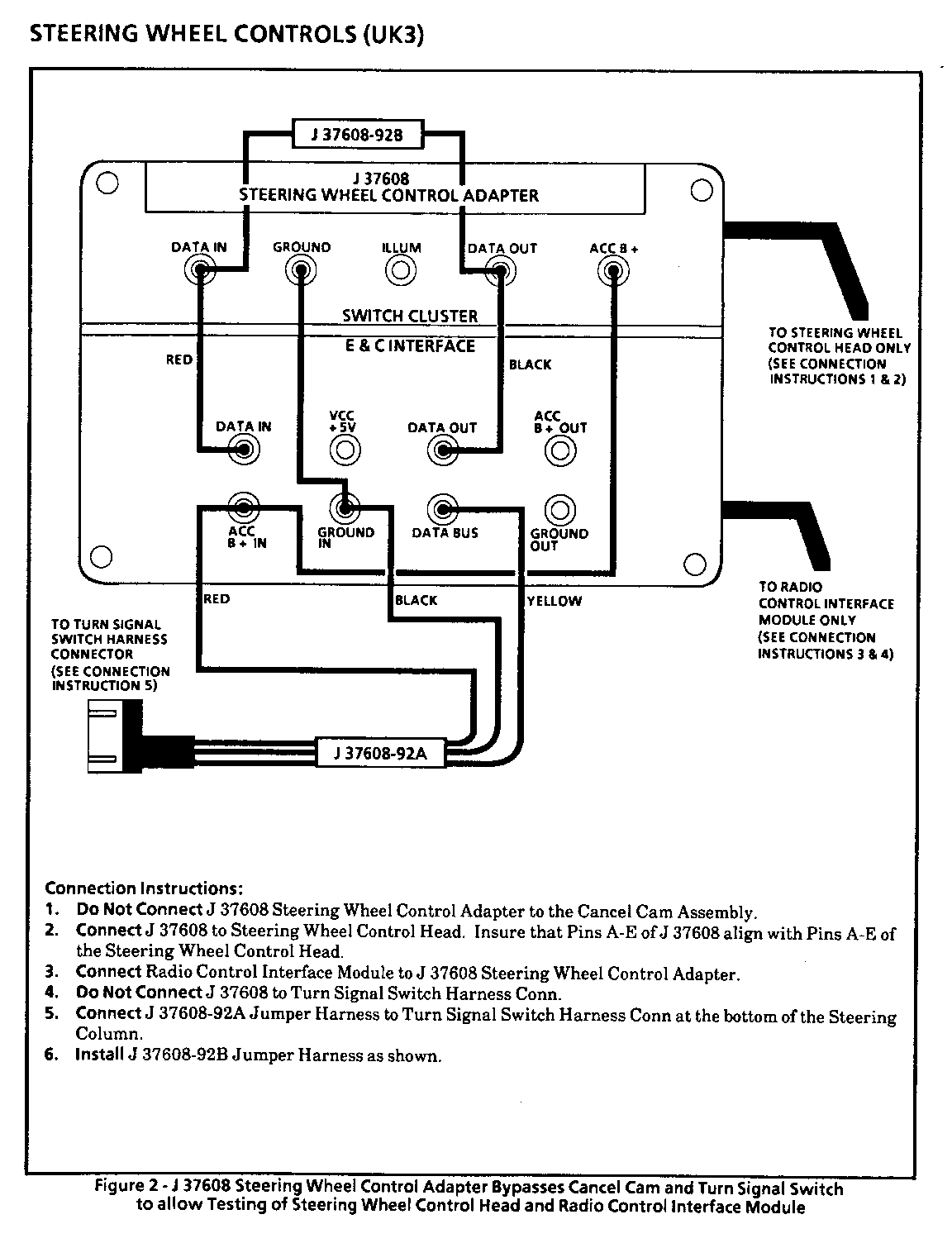
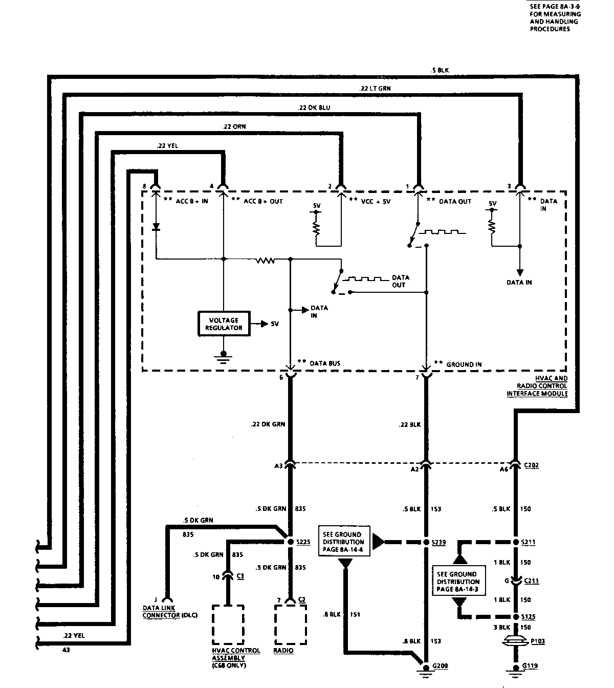
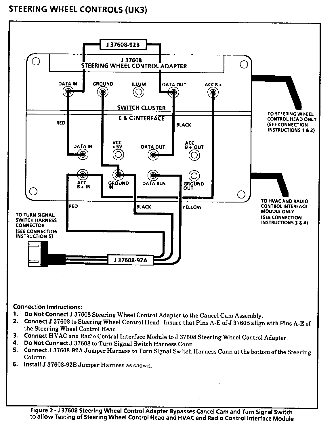
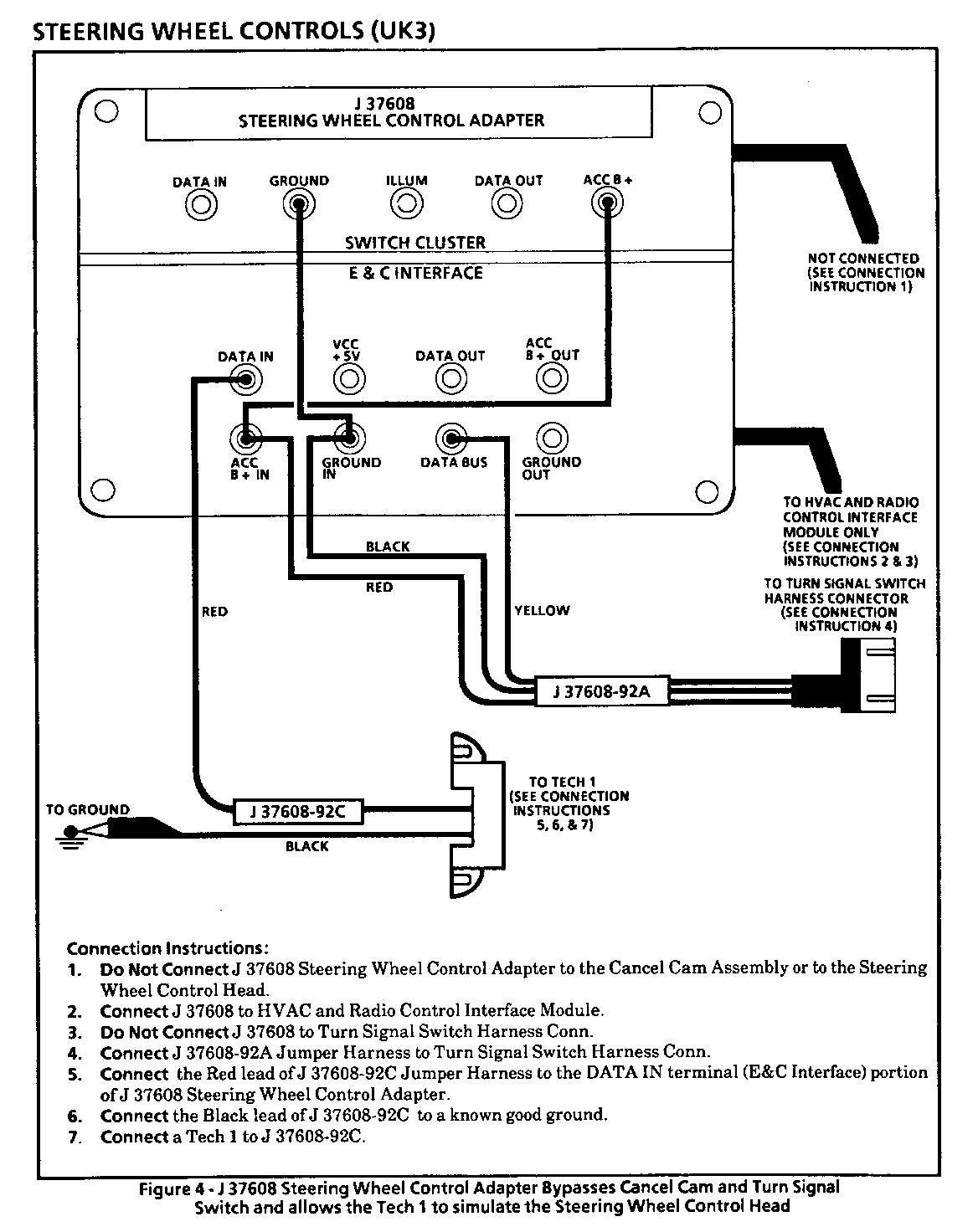
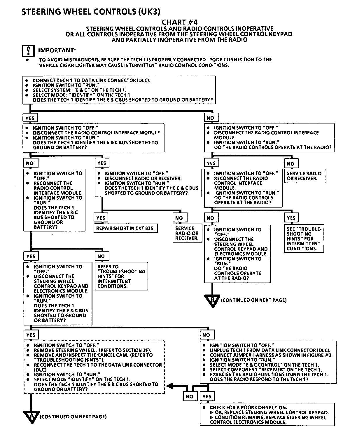
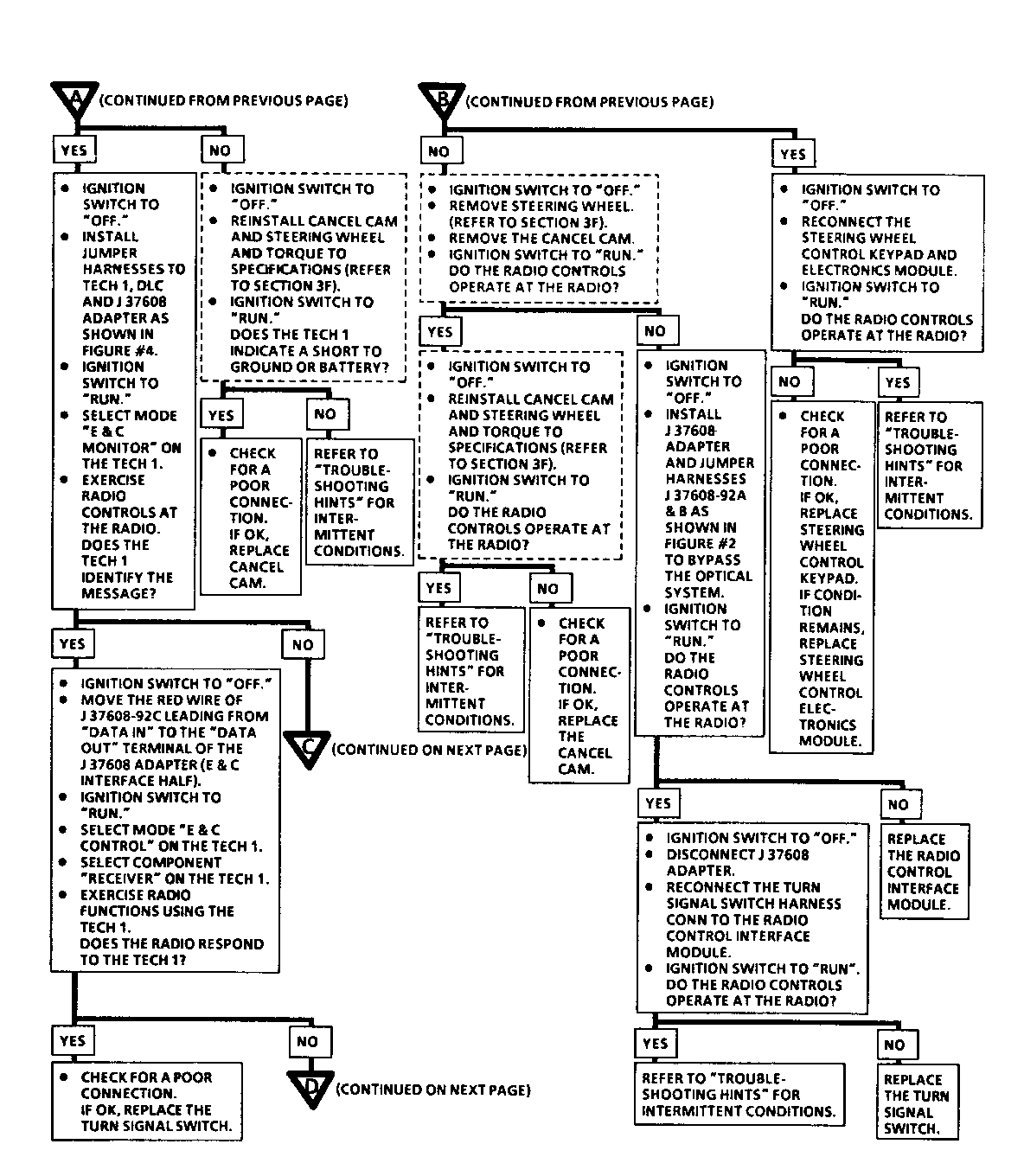
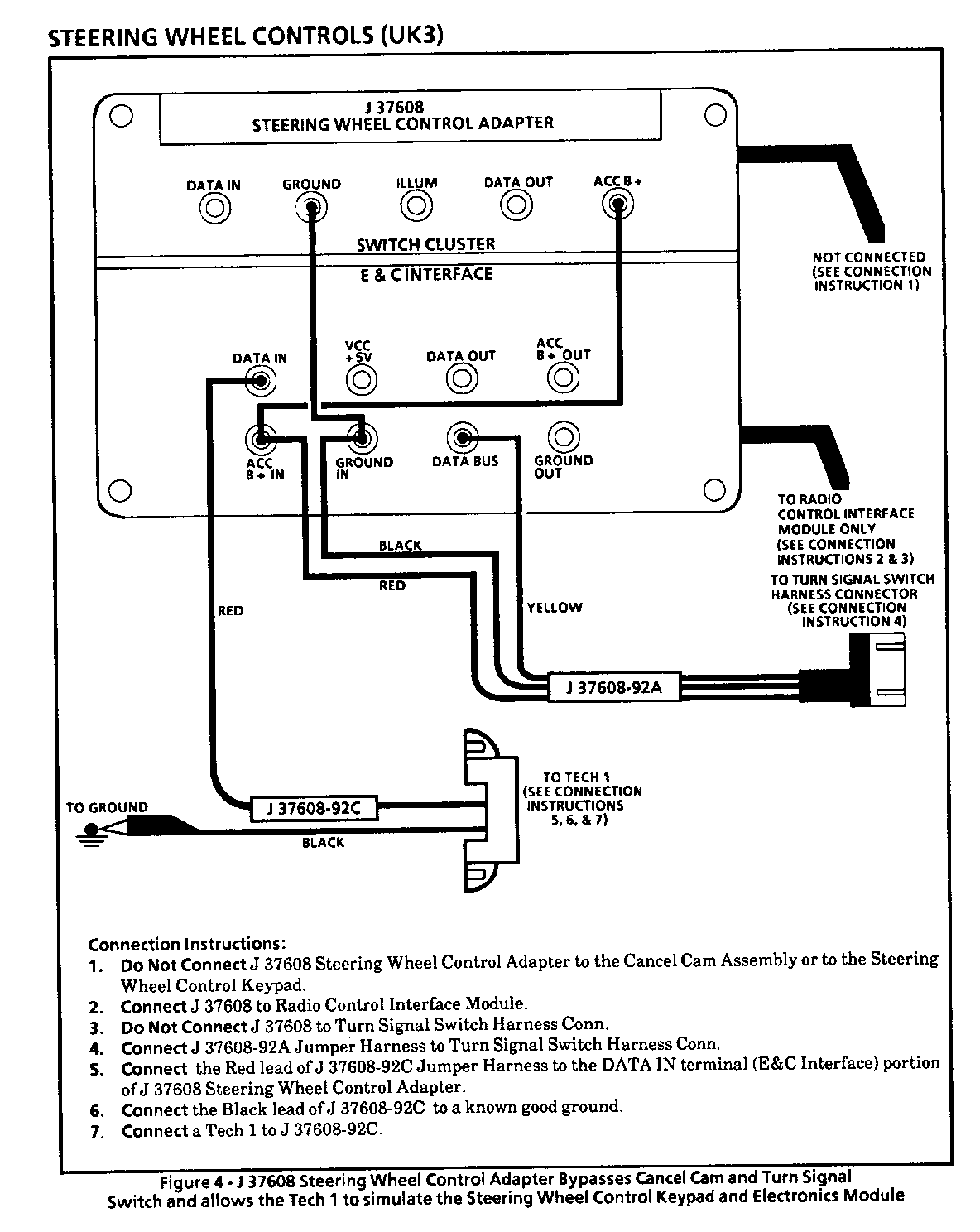
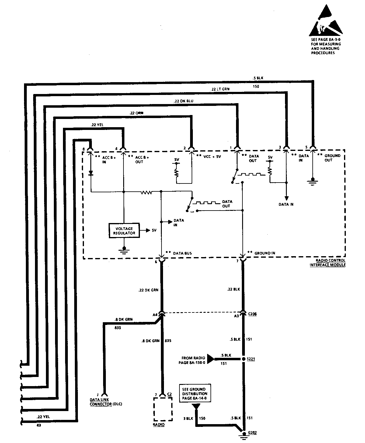
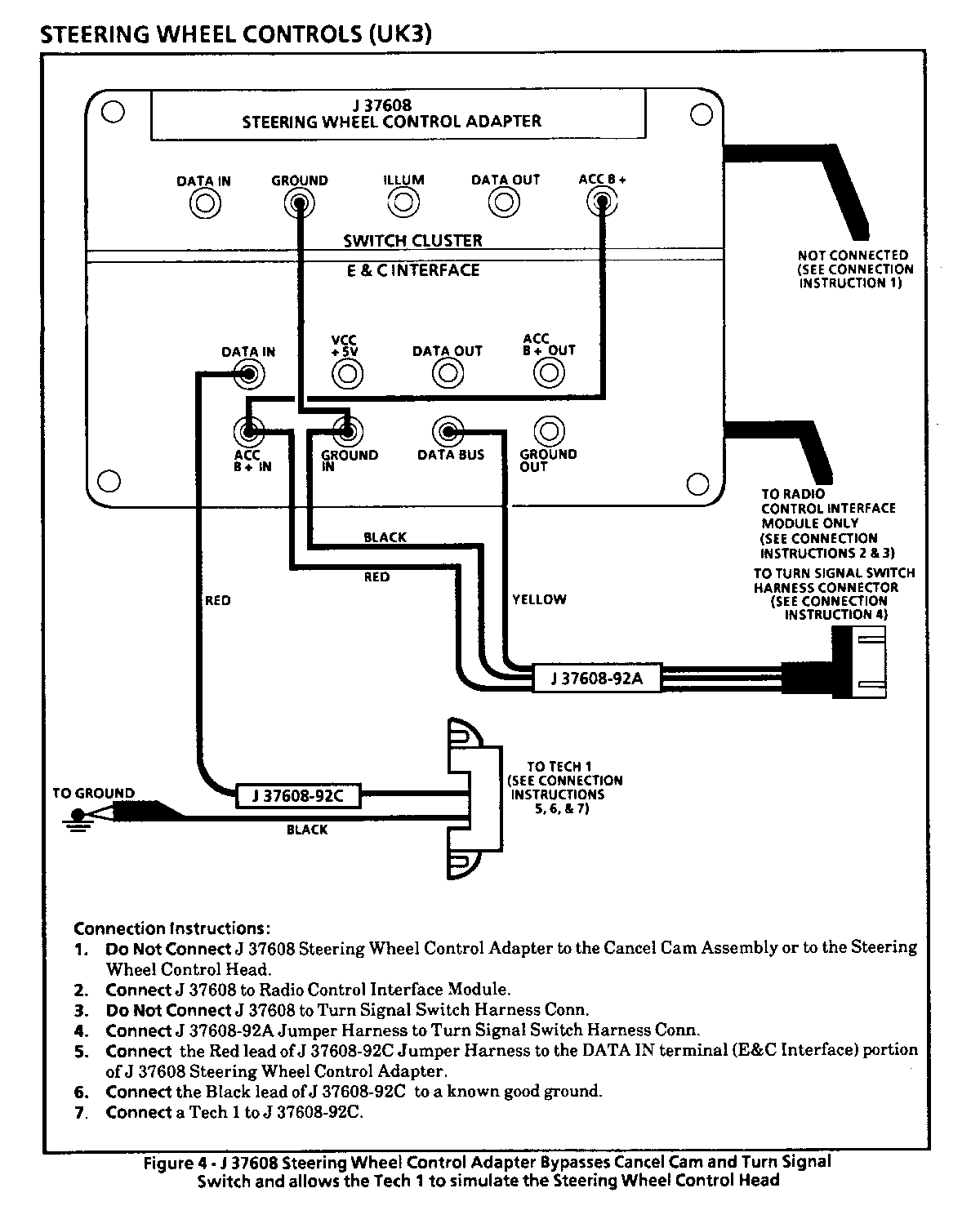
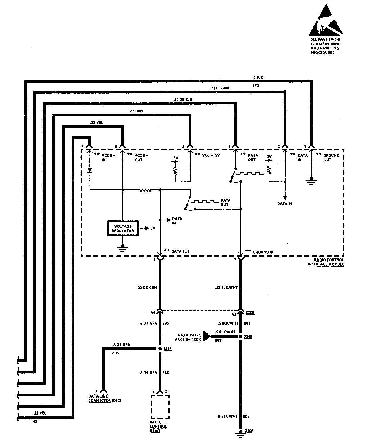
J37608-92A (Jumper Harness) - This jumper harness connects to the vehicle connector that plugs into the E & C Interfar-e Module. This allows for Battery, Ground, and the E & C Data line (CKT 835) to be connected to the SWC Adapter; which can power up the SWC head or keypad and the E & C Interface module. Thus, the Cancel Cam Assembly and Tum Signal Switch can be bypassed and allow for testing of the E & C Interface Module and the SWC head or keypad.
J37608-92B (Jumper Harness) - This jumper harness allows Data In and Data Out messages to be sent without the Cancel Cam Assembly and the Tum Signal Switch in the system. When bypassing these components, if the SWC problem disappears; a problem exists with either the Cancel Cam Assembly or the Turn Signal Switch. If the problem remains, the fault is due to one of the remaining SWC components.
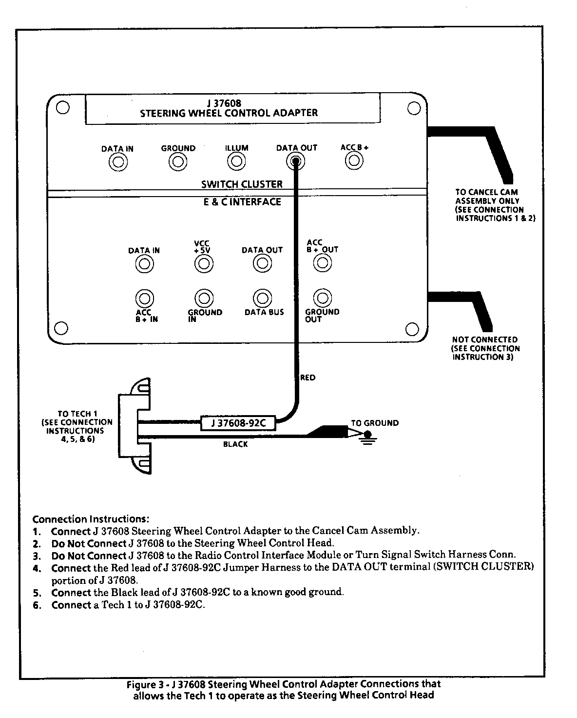
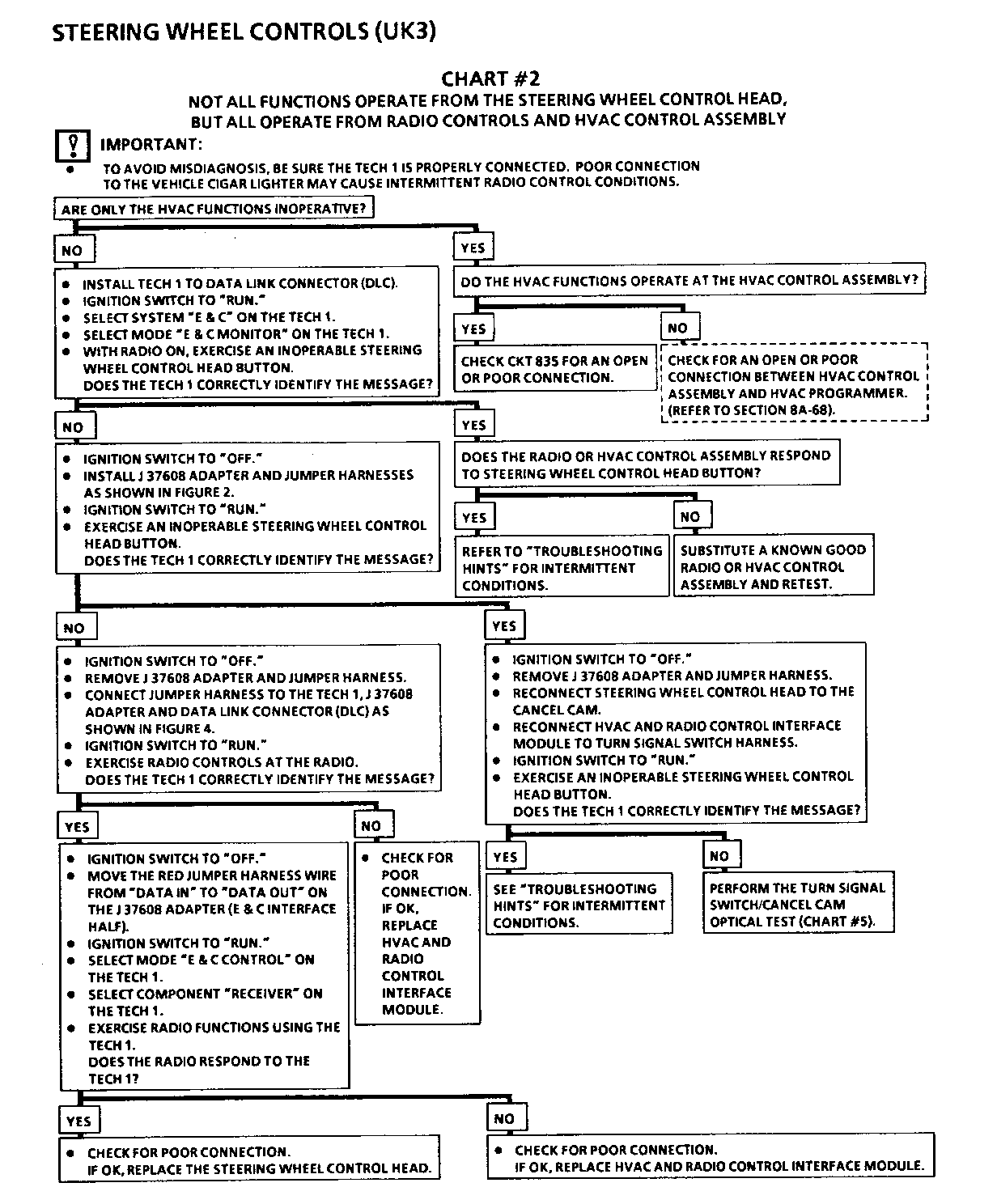
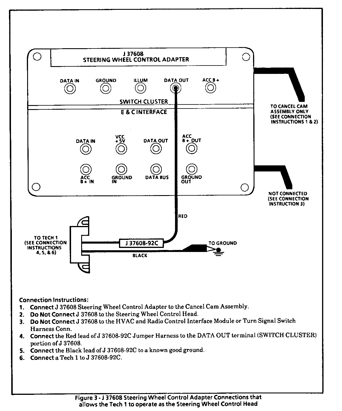
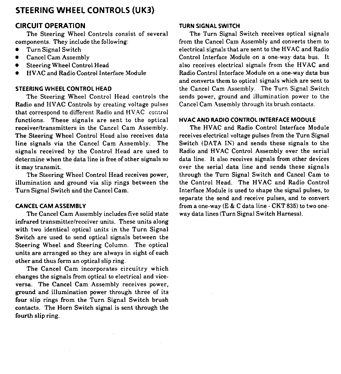
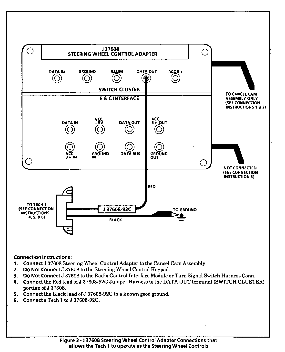
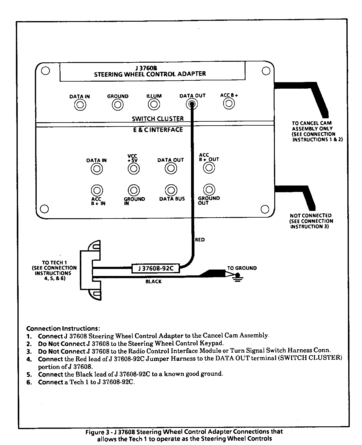
J37608-92C (Jumper Harness) - This jumper hamess has a connector similar to the Data Link Connector (DLC) which the TECH 1 can be connected to and a ground wire which provides proper grounding of the TECH 1. The TECH 1 is used to monitor Entertainment & Comfort (E & C) data messages that are sent from the SWC head, SWC keypad, HVAC head and the Radio or to simulate the SWC head or keypad by sending messages through the SWC components.
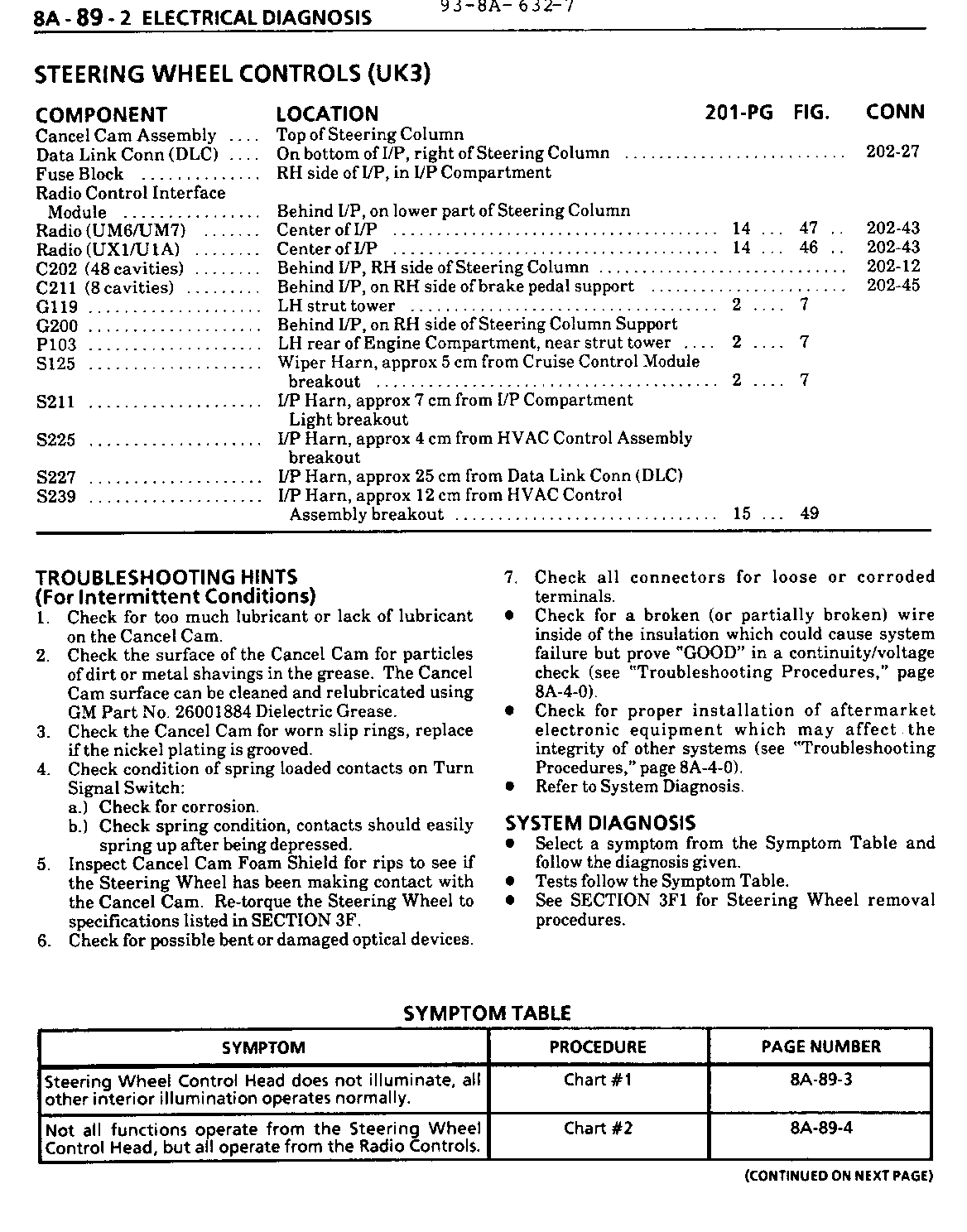
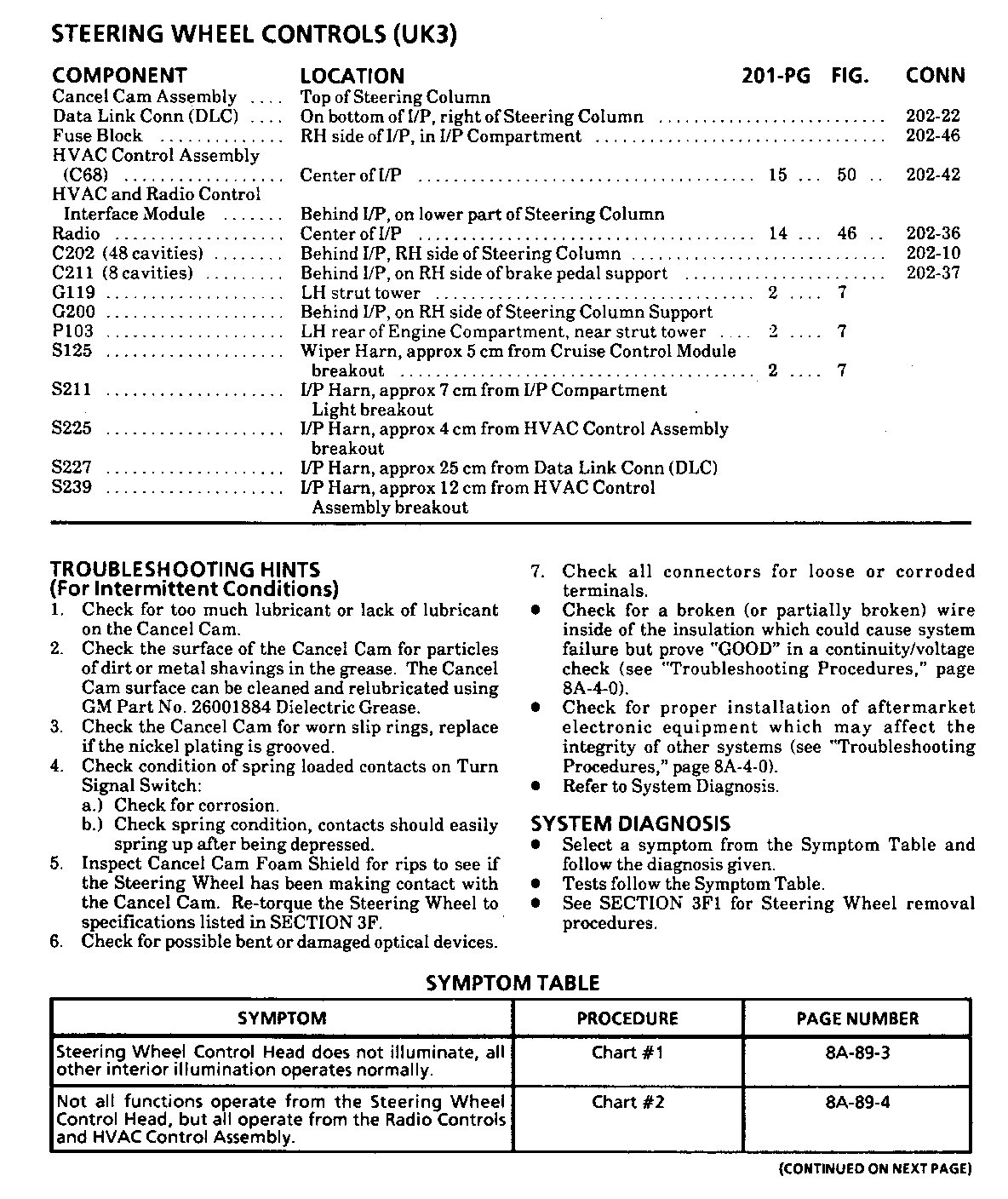
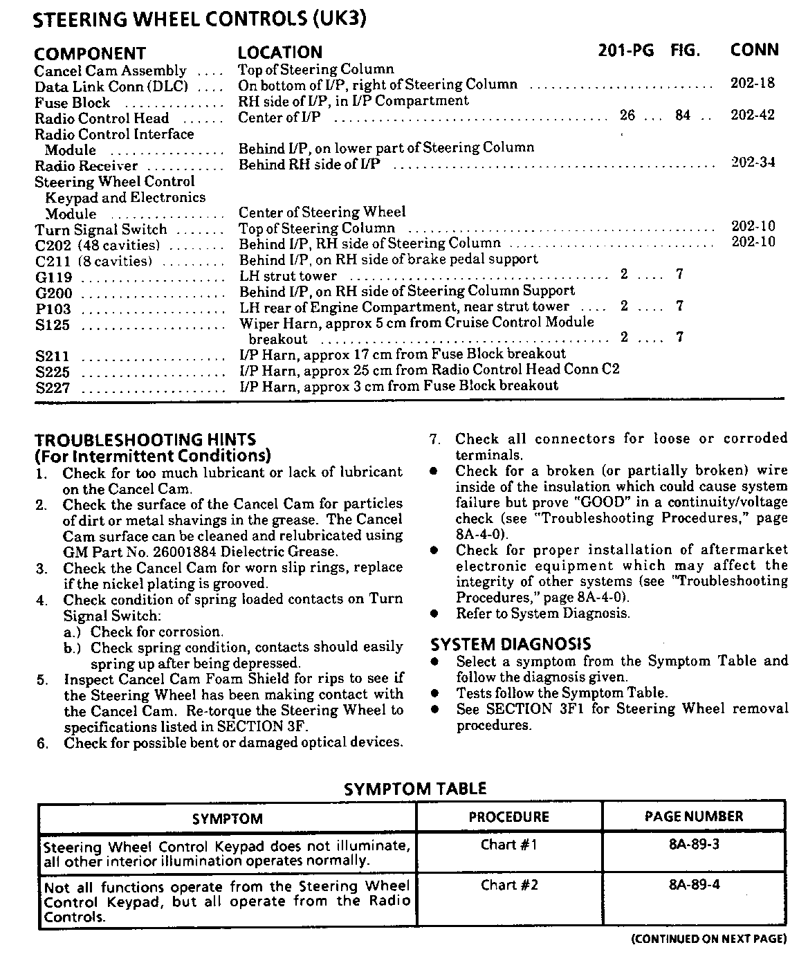
Use the new diagnostic information included here in place of that found in Section 8A-89 in the Service Manual.
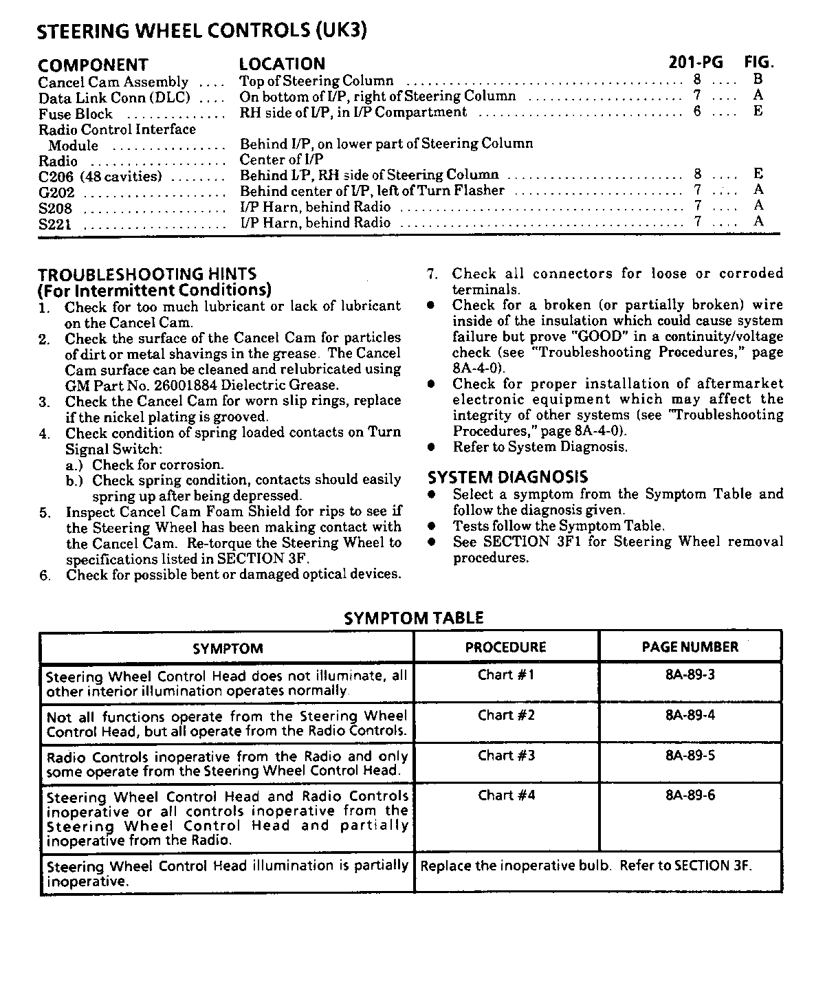
The following updated information applies to the Sound Service Audio Systems Diagnostics Guide.
When using the Sound Service Audio Systems Diagnostics Guide to diagnose optical Steering Wheel Control complaints:
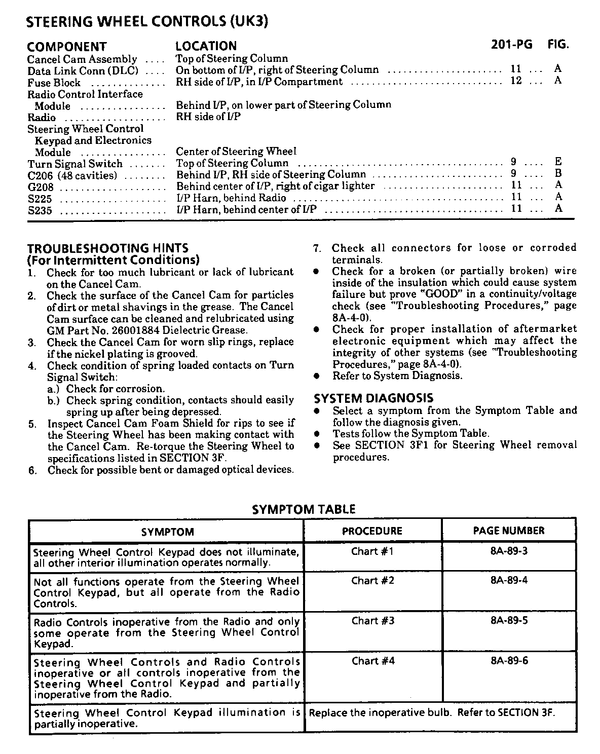
Refer to pages (5-43 - 5-53) for the symptom table and diagnostic charts.
Refer to pages (5-54 - 5-56) for jumper hamess connection instructions.
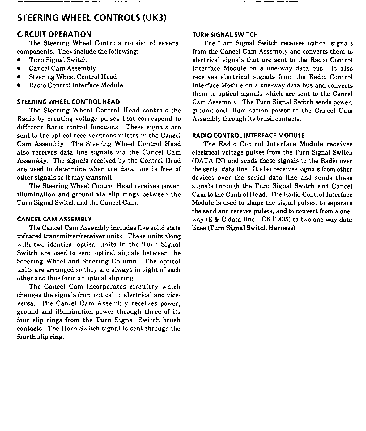
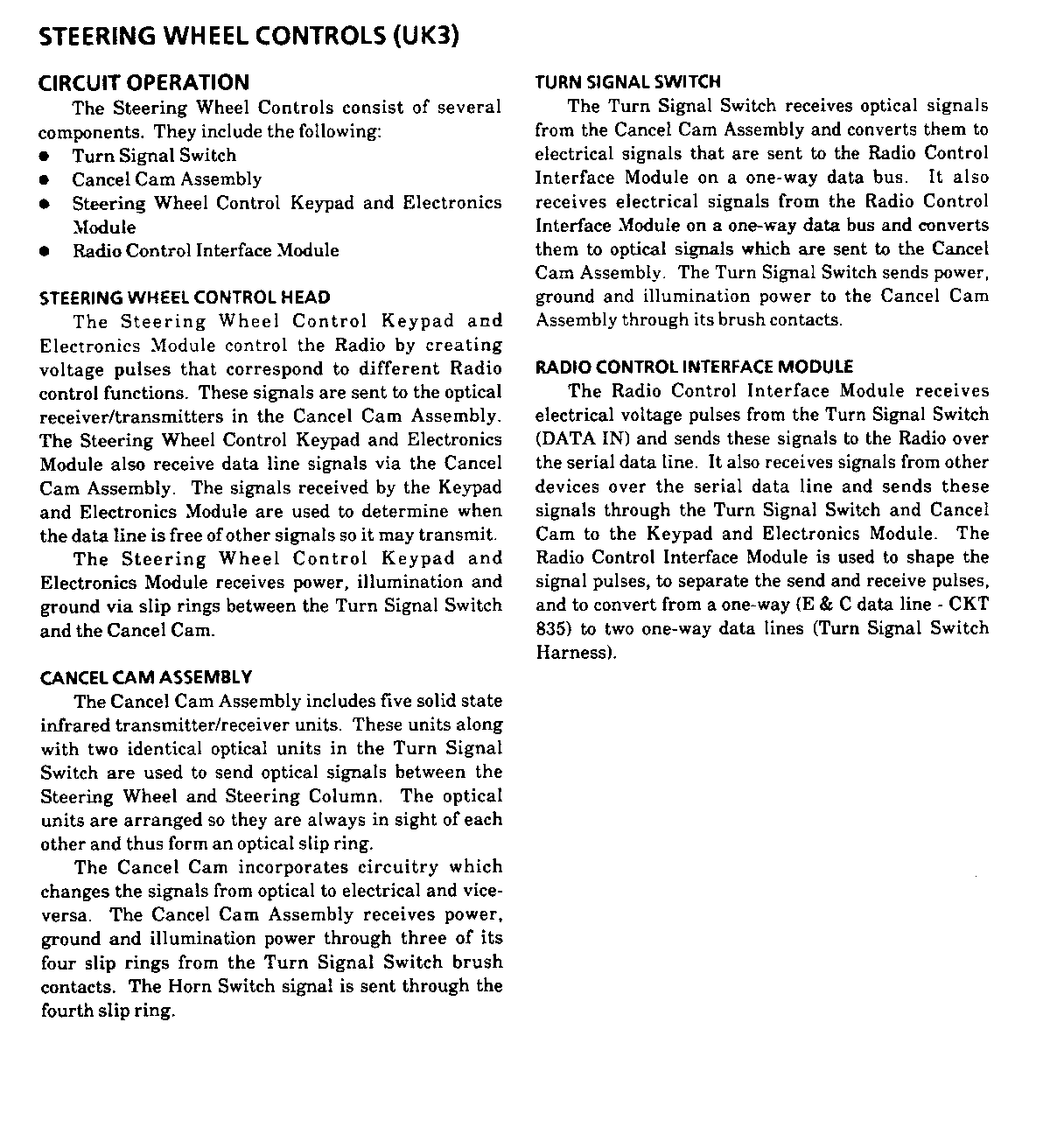
Refer to pages (2-17 - 2-20) for component and circuit descriptions.
Revisions to the Delco Electronics Sound Service Audio Systems Diagnostics Guide.
Important: To avoid misdiagnosis, after selecting the appropriate symptom from the symptom table, refer to these revisions for the appropriate chart.
ALL CHARTS
Before replacing any SWC components, check for poor connections or bent terminals.
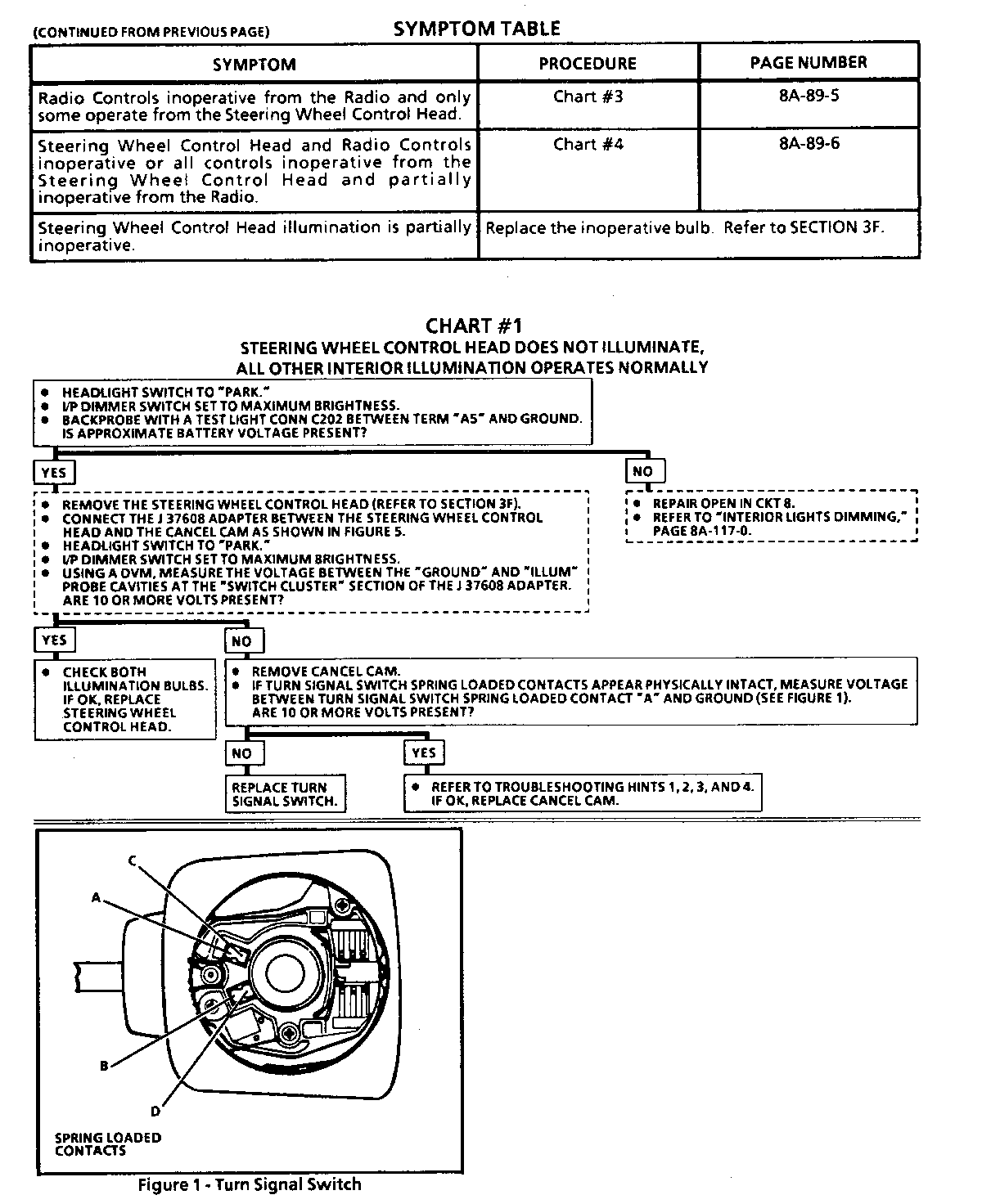
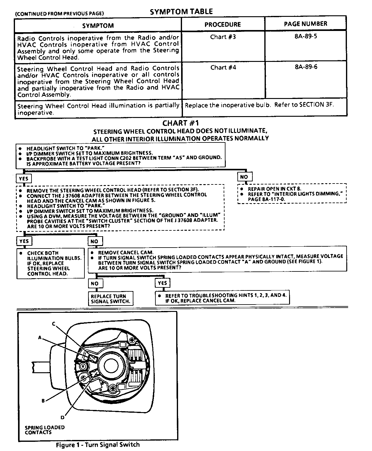
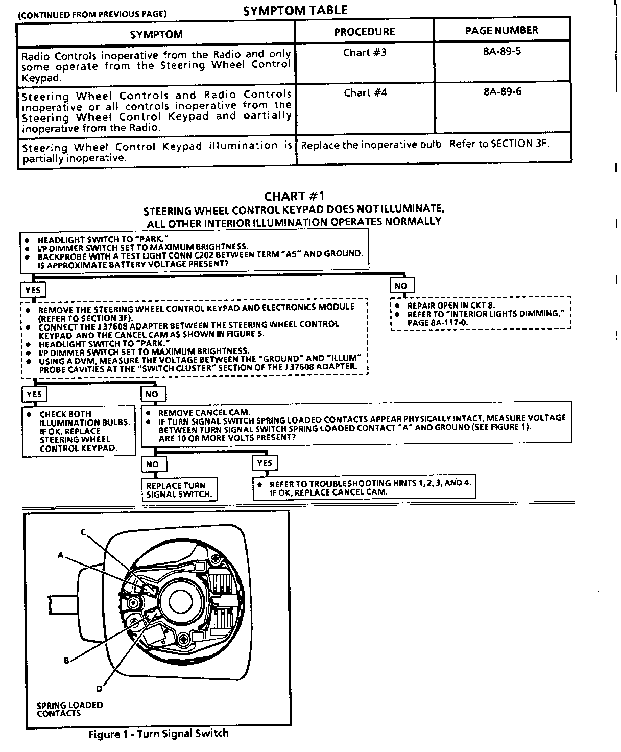
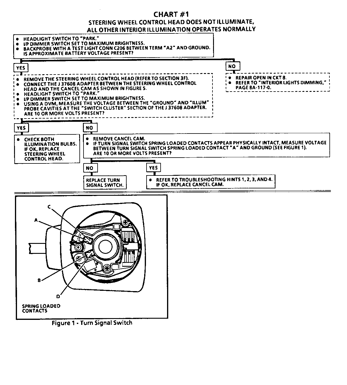
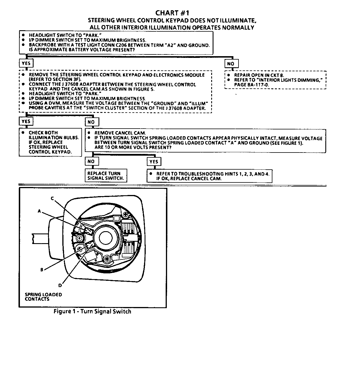
Chart 1 SWC Head Illumination does not come on with Park lights or Headlights
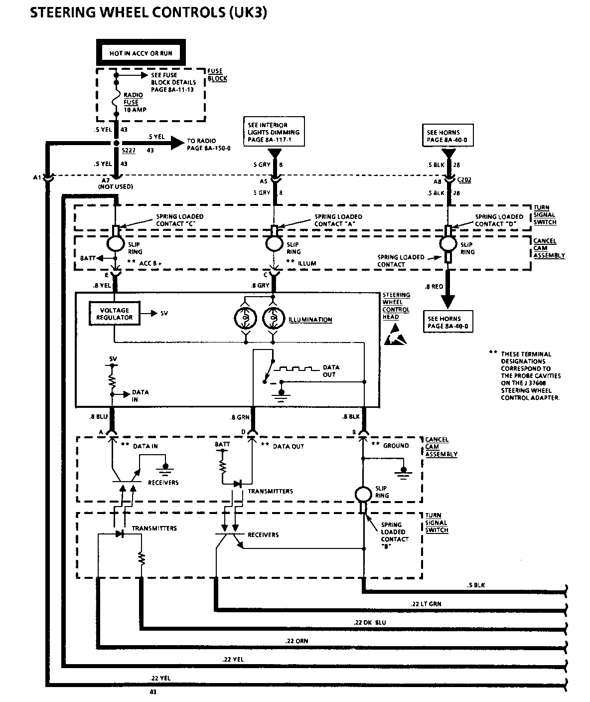
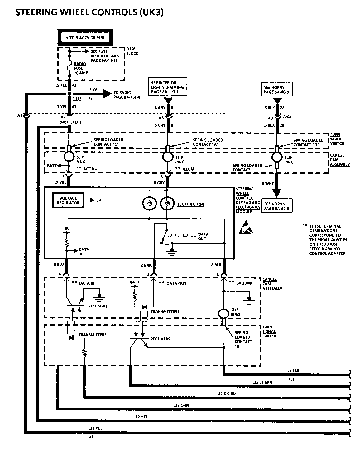
The Turn Signal Switch (TSS) illumination wire should be checked by measuring the voltage to ground at the TSS illumination spring loaded brush. If 11 or more volts are not present; replace the TSS. If 1 1 or more volts are present, perform Cancel Cam checks as listed. If OK, replace the Cancel Cam.
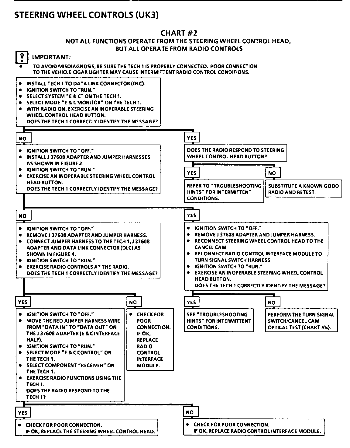
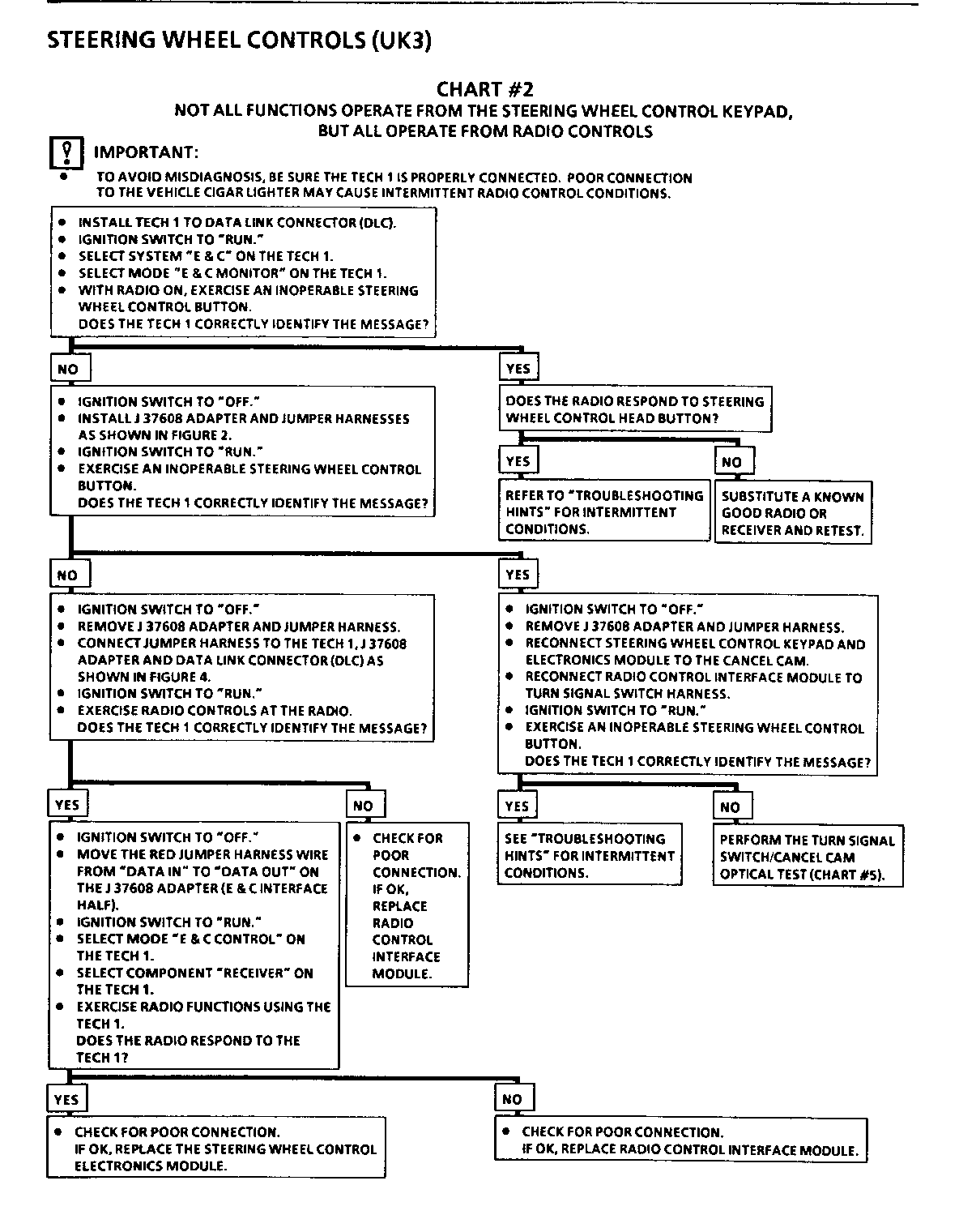
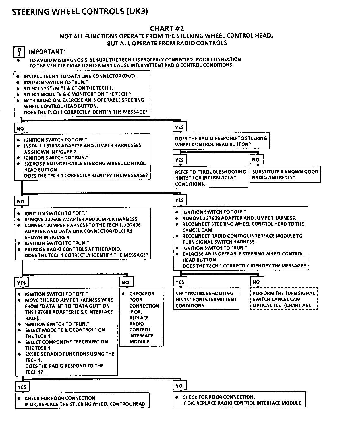
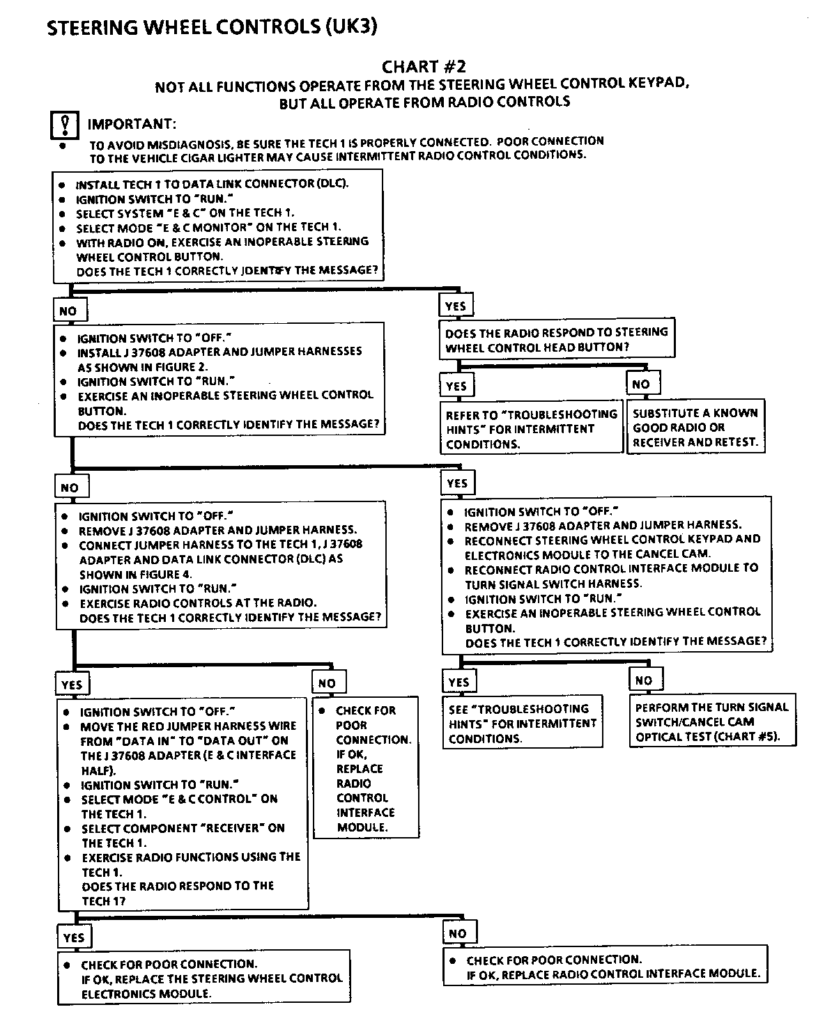
Chart 2 Only some functions operate from the Steering Wheel Controls but all functions operate from the Radio Controls
Spelling Typo in box on the left hand side - Check for an open circuit in the E&C data line or for poor connections at the HVAC Control Head.
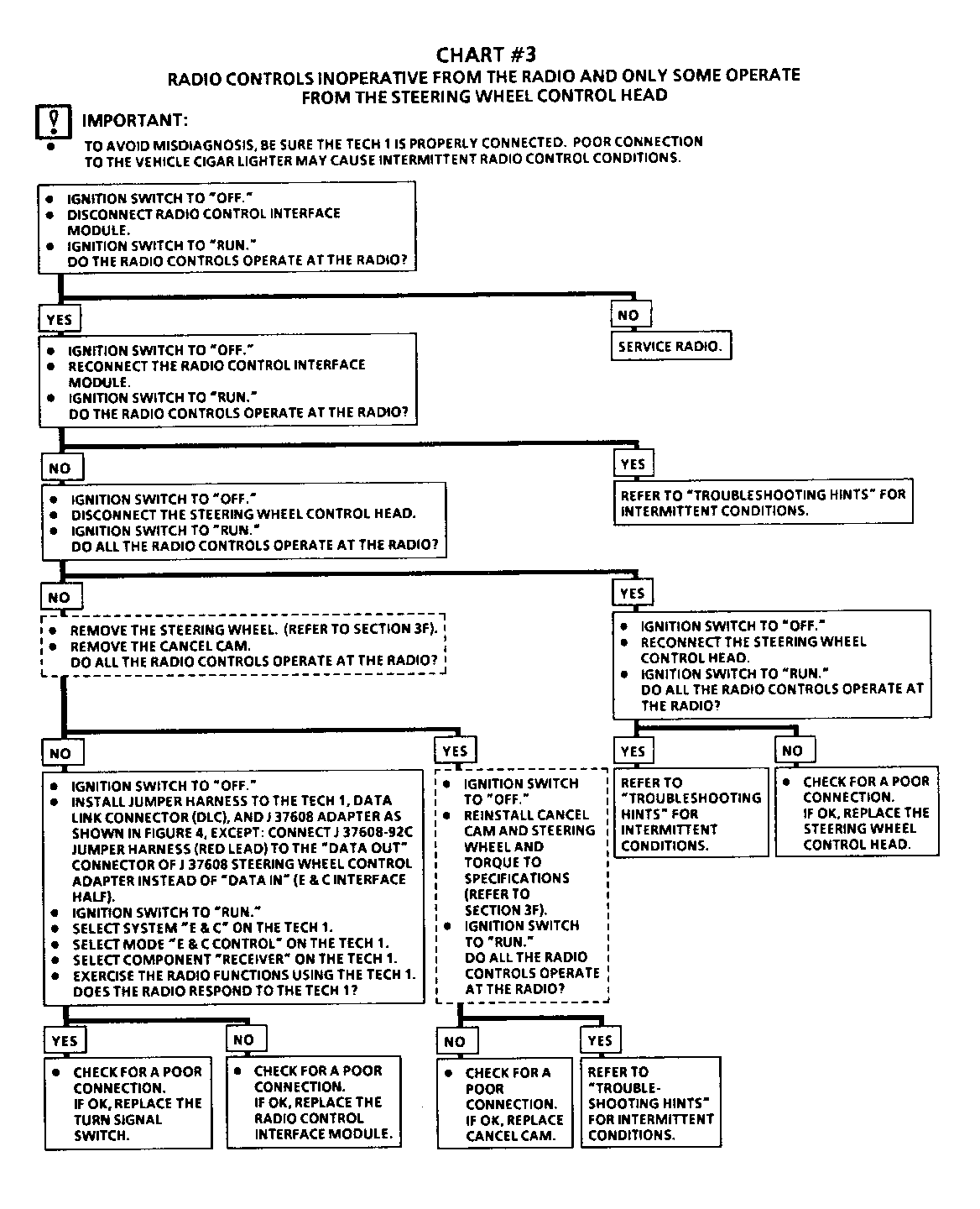
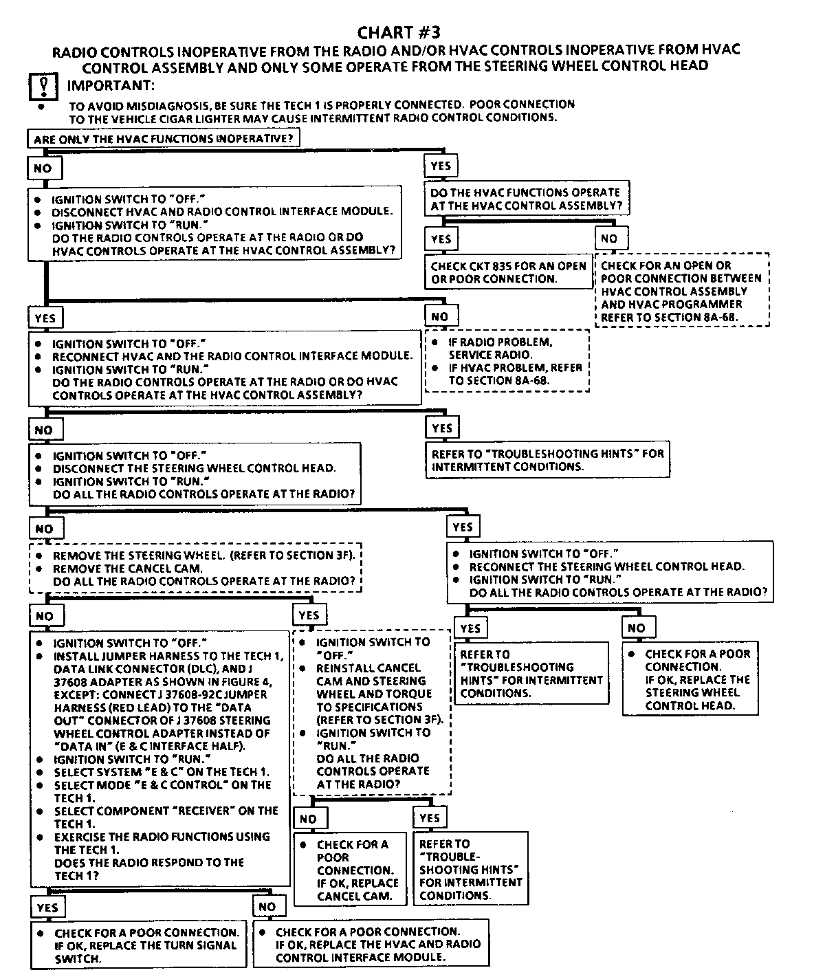
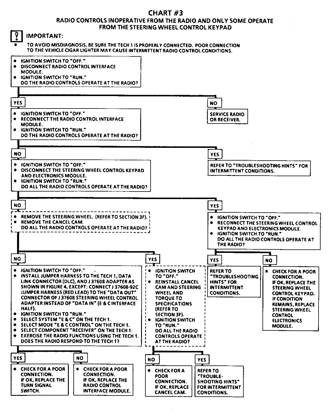
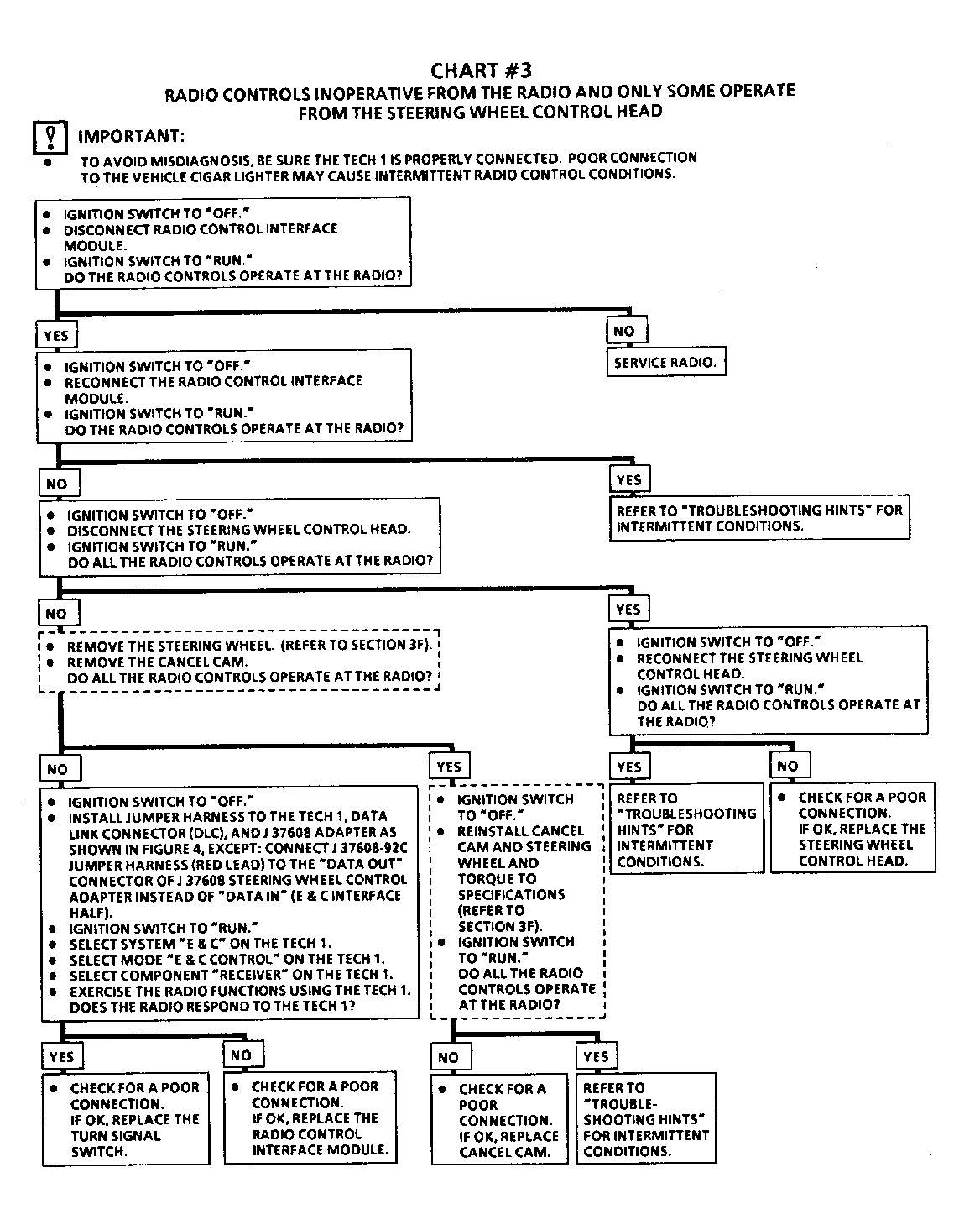
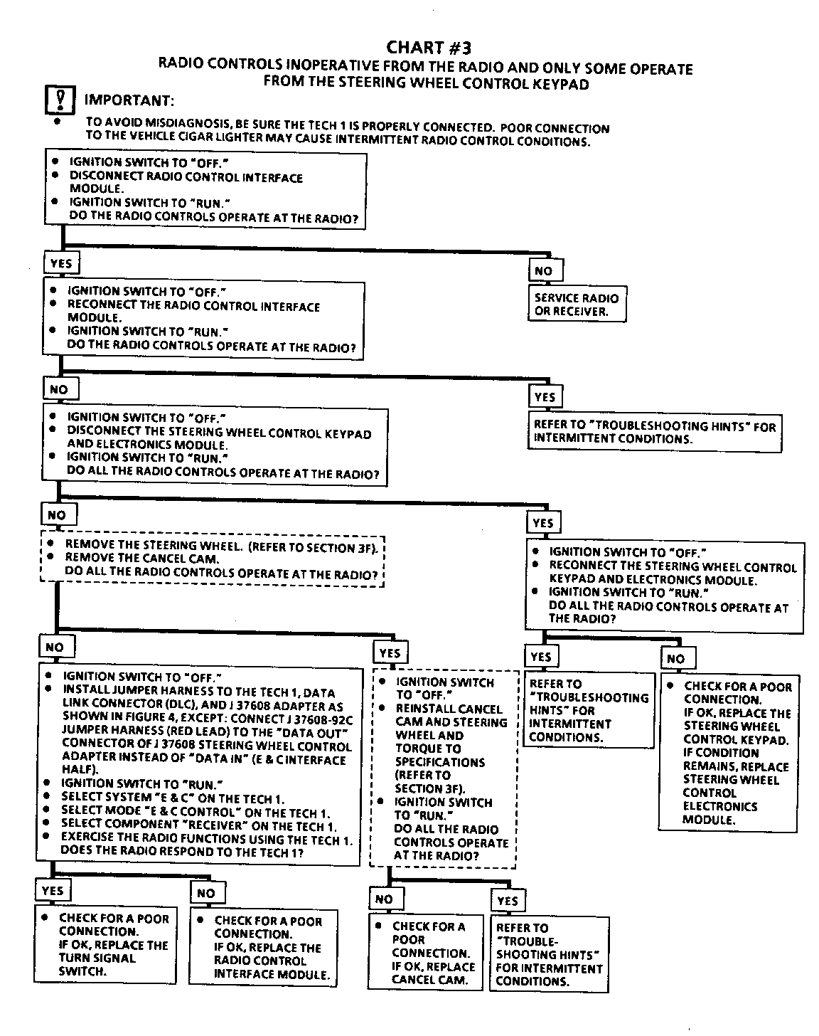
Chart 3 None of the functions operate from the Steering Wheel Controls but all functions operate from the Radio Controls
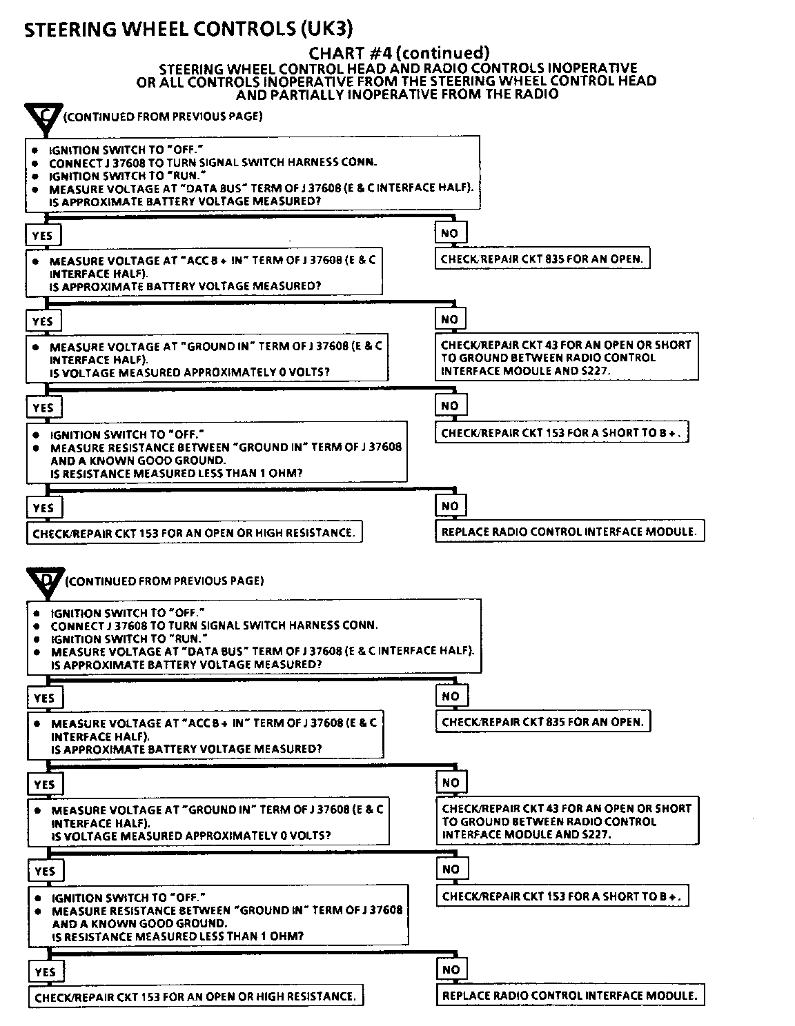
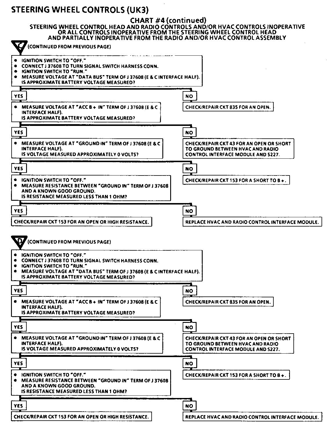
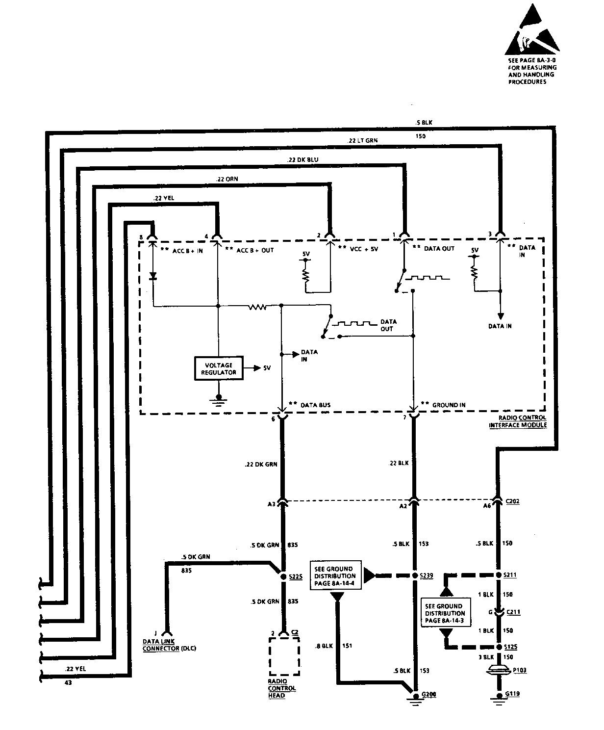
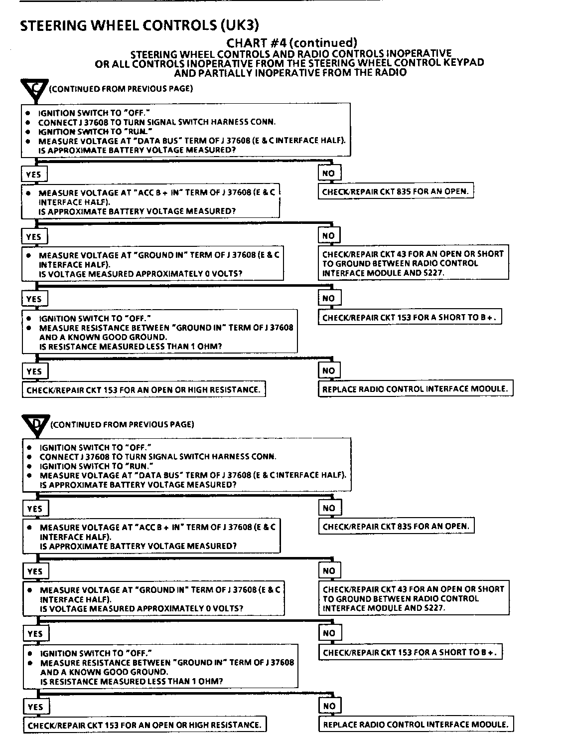
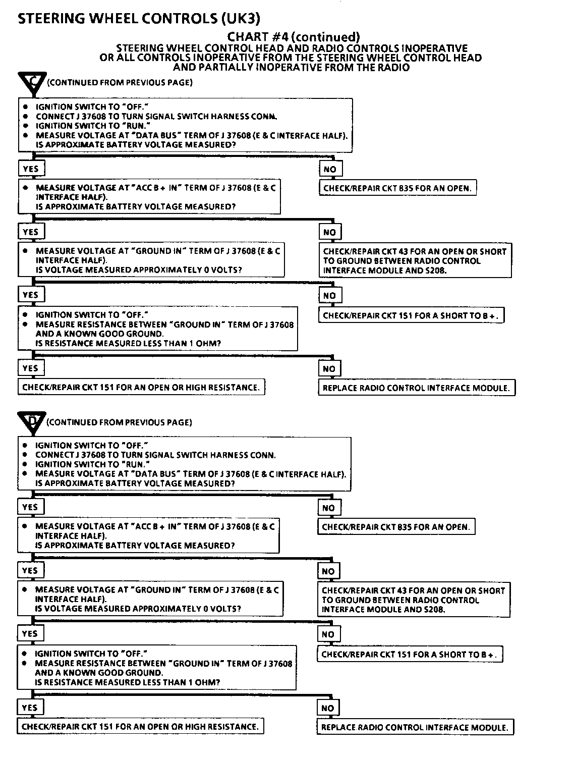
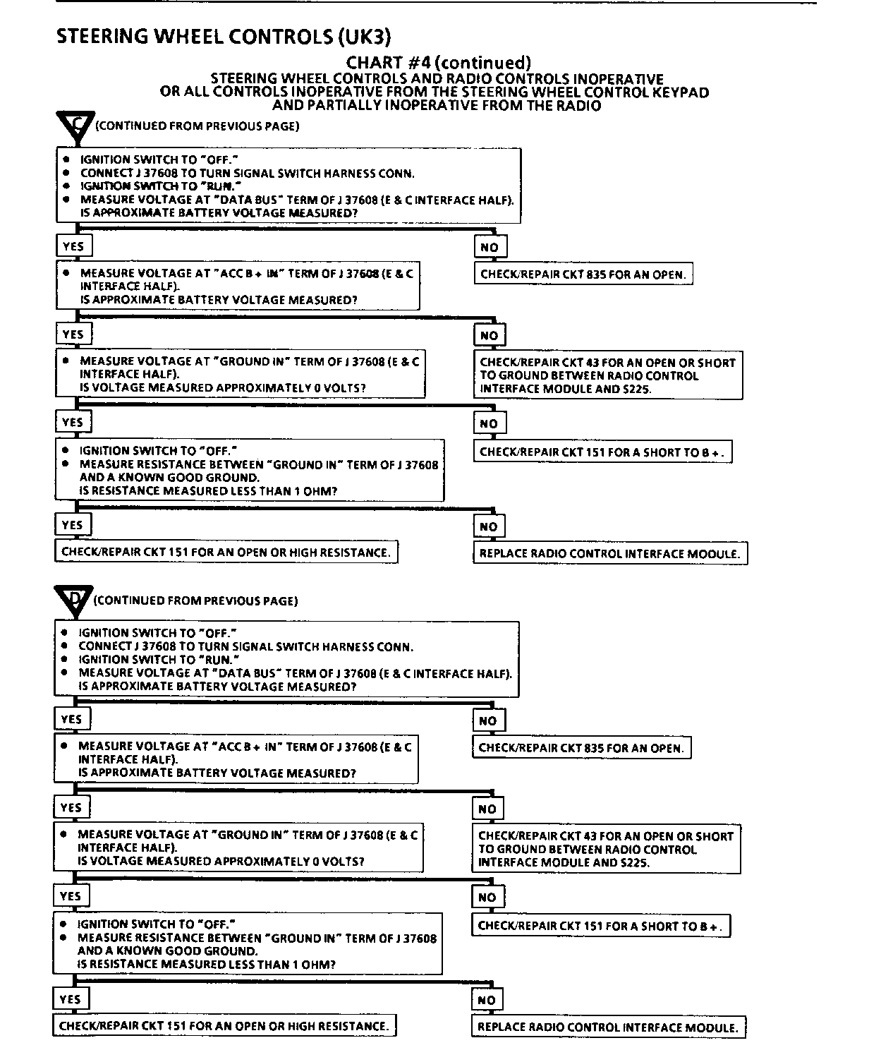
There are two boxes that instruct you to "Replace the E&C Interface Module". Before replacing the module, check the battery, ground, and E&C data circuits that connect to the module. Ignition switch 'OFF'. Remove the jumper harnesses from J37608. Connect the Radio & HVAC Interface Module portion of the Tum Signal Switch harness to J37608. With the Ignition Switch in Run, make the following voltage measurements at the E&C Interface half of J37608:
J37608 Pin Expected Measurement If measurement wrong ---------- -------------------- -------------------- Data Bus Approx. Bat Voltage Check for open in E & C Data line (Ckt 835)
Acc B+ In Battery Voltage Check battery feed to E&C Interface Module for short to ground or an open circuit
Ground IN Approx. 0 Volts Check for short in ground wire to E&C Interface Module
With the Ignition Switch Off, measure the resistance between the Ground In terminal of J37608 and a known good ground. If resistance is more than 0.5 ohms, repair high resistance in ground wire to E&C Interface module. If OK, replace the E&C Interface Module.
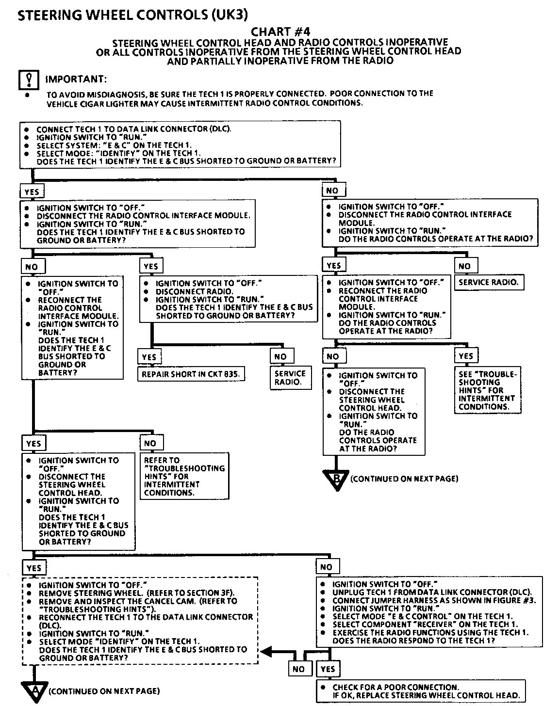
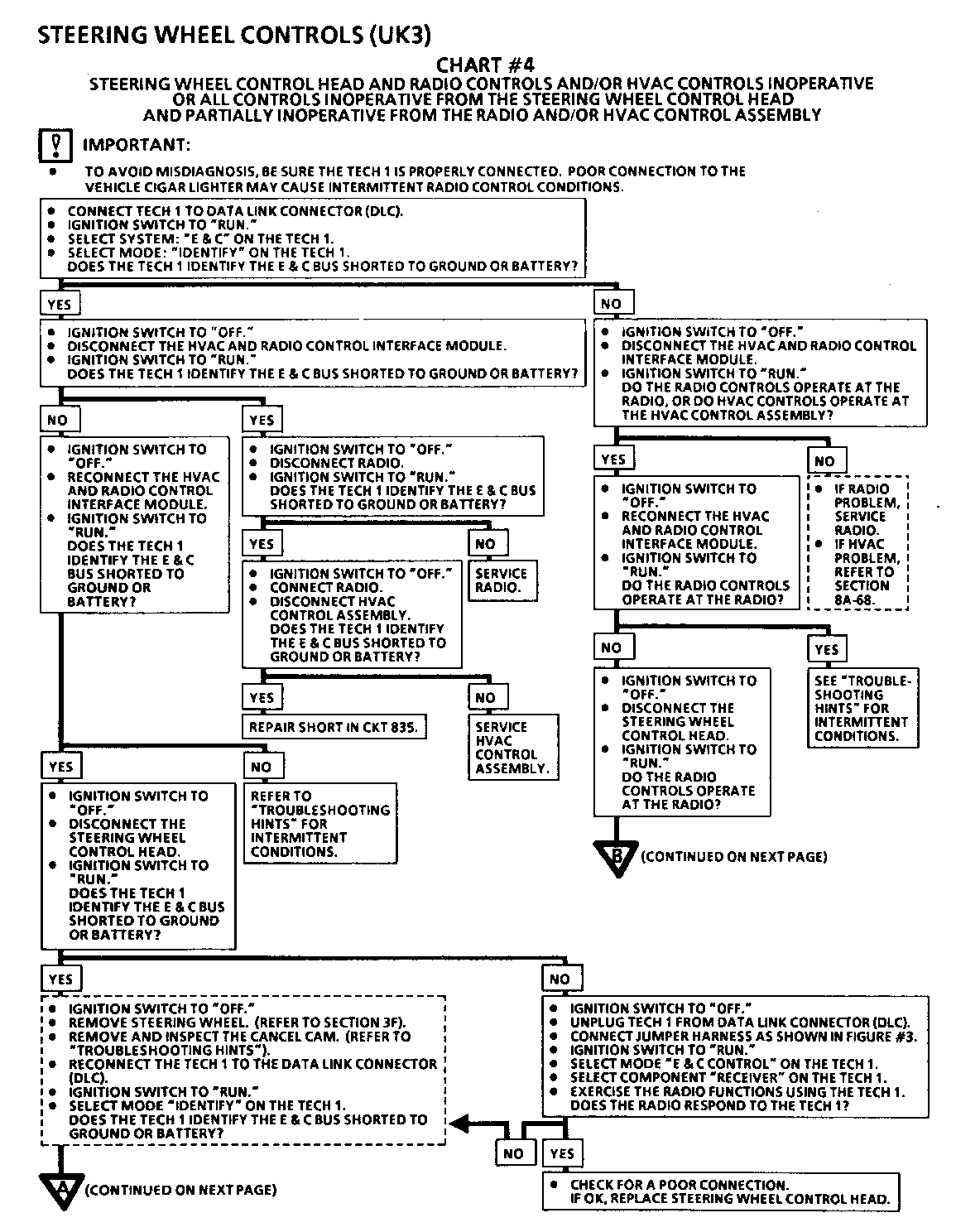
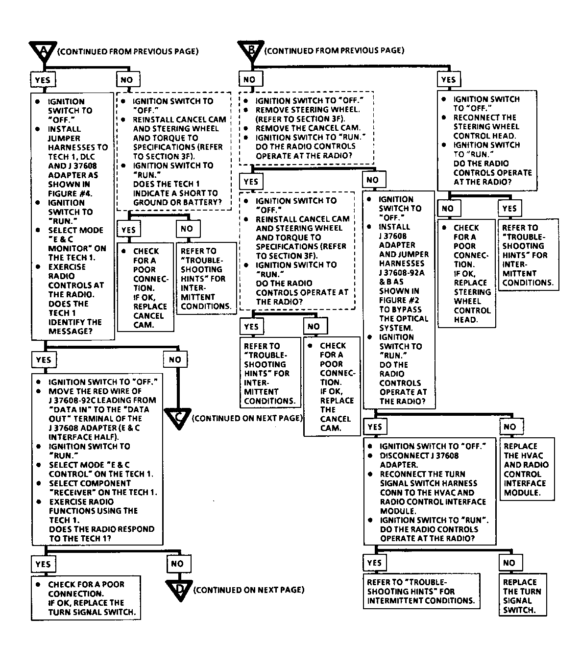
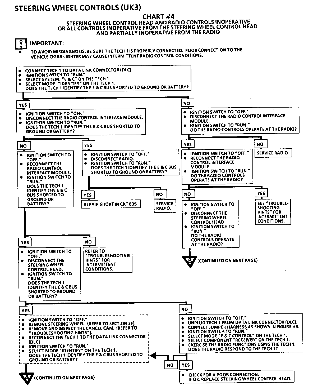
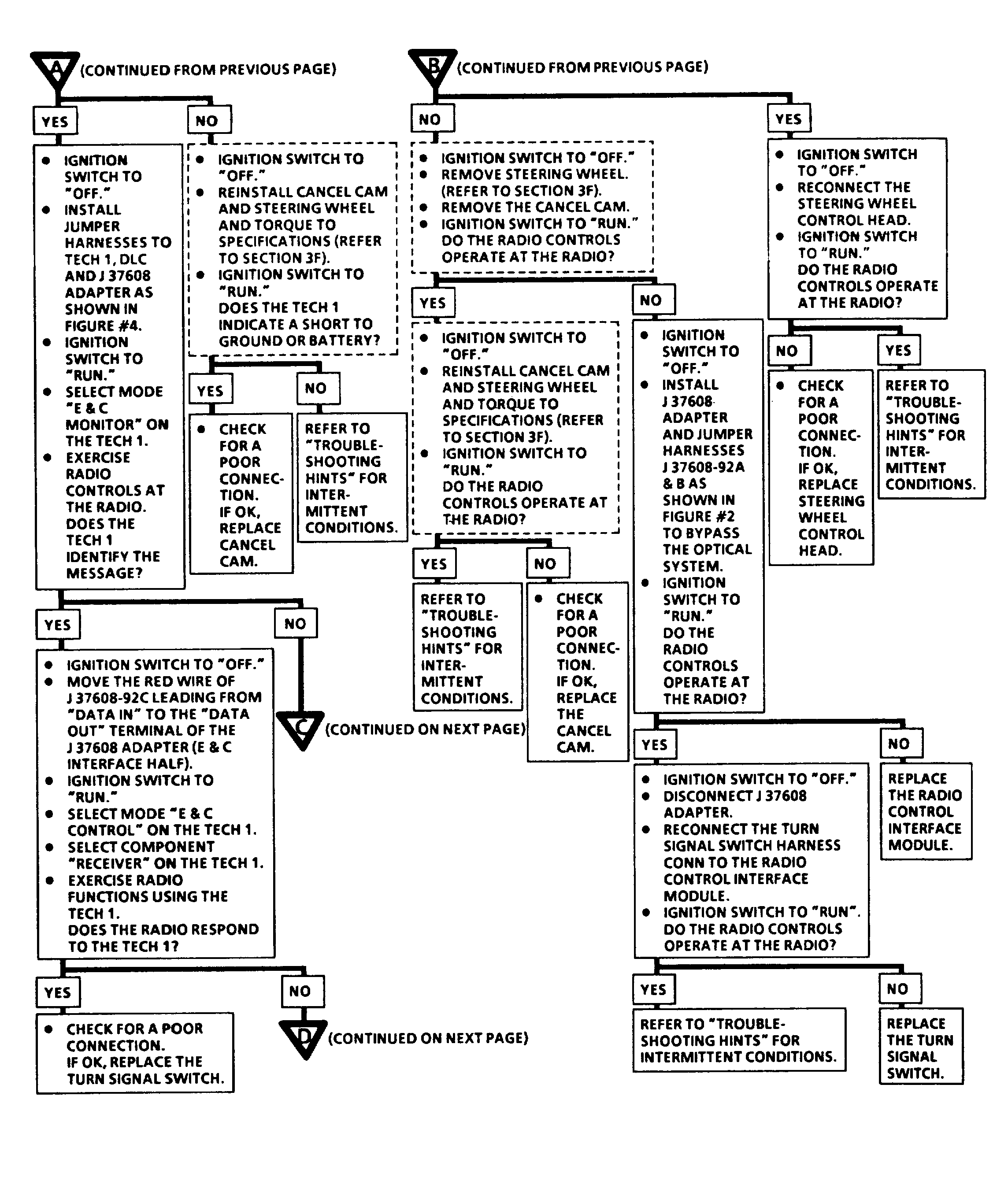
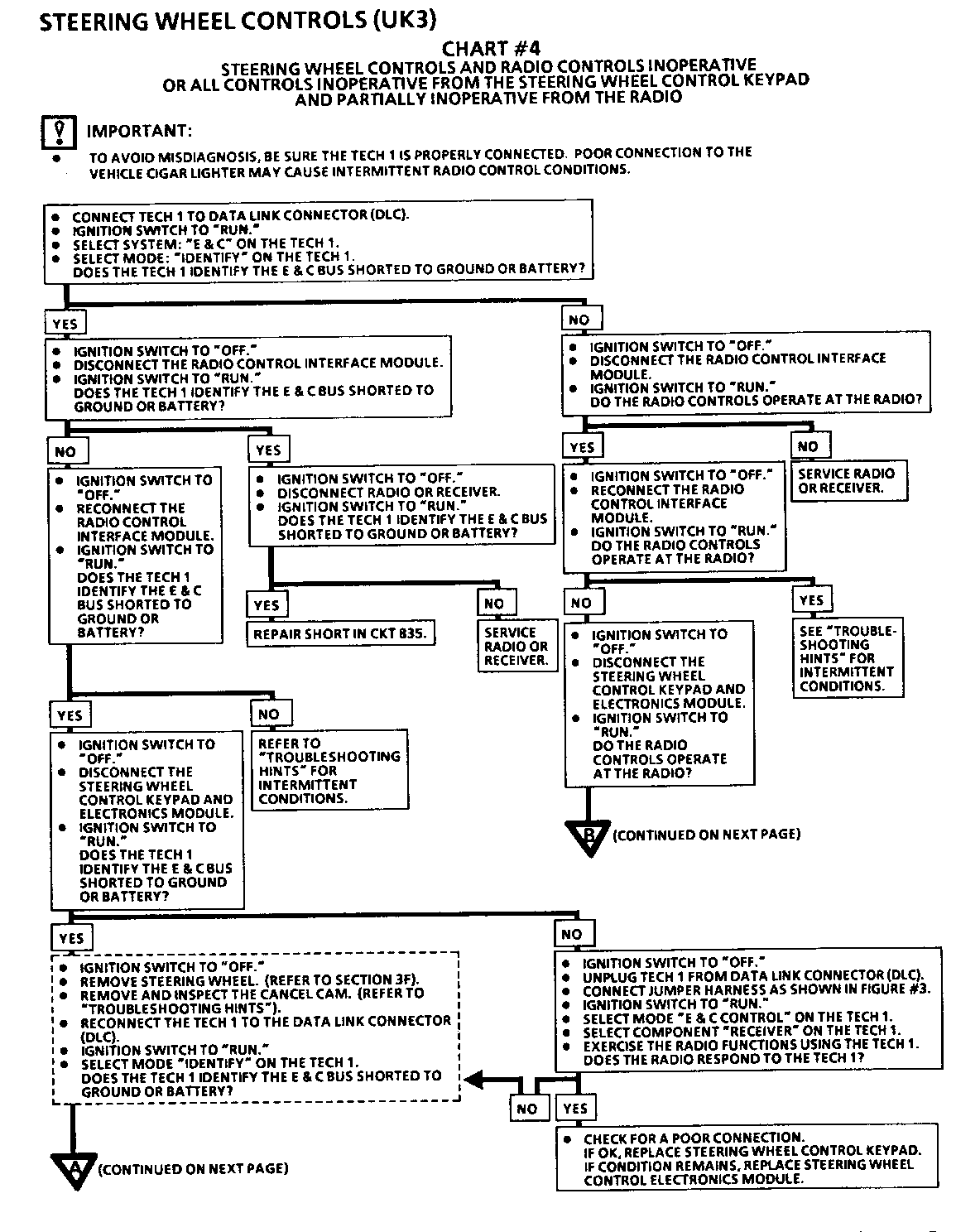
Chart 4 Only some functions operate from the Steering Wheel Controls and none of the functions operate from the Radio Controls
If you respond yes to the question: Are only the HVAC commands working? Before servicing the radio, check for an open circuit in the E&C data line going to the radio or for poor connections at the radio.
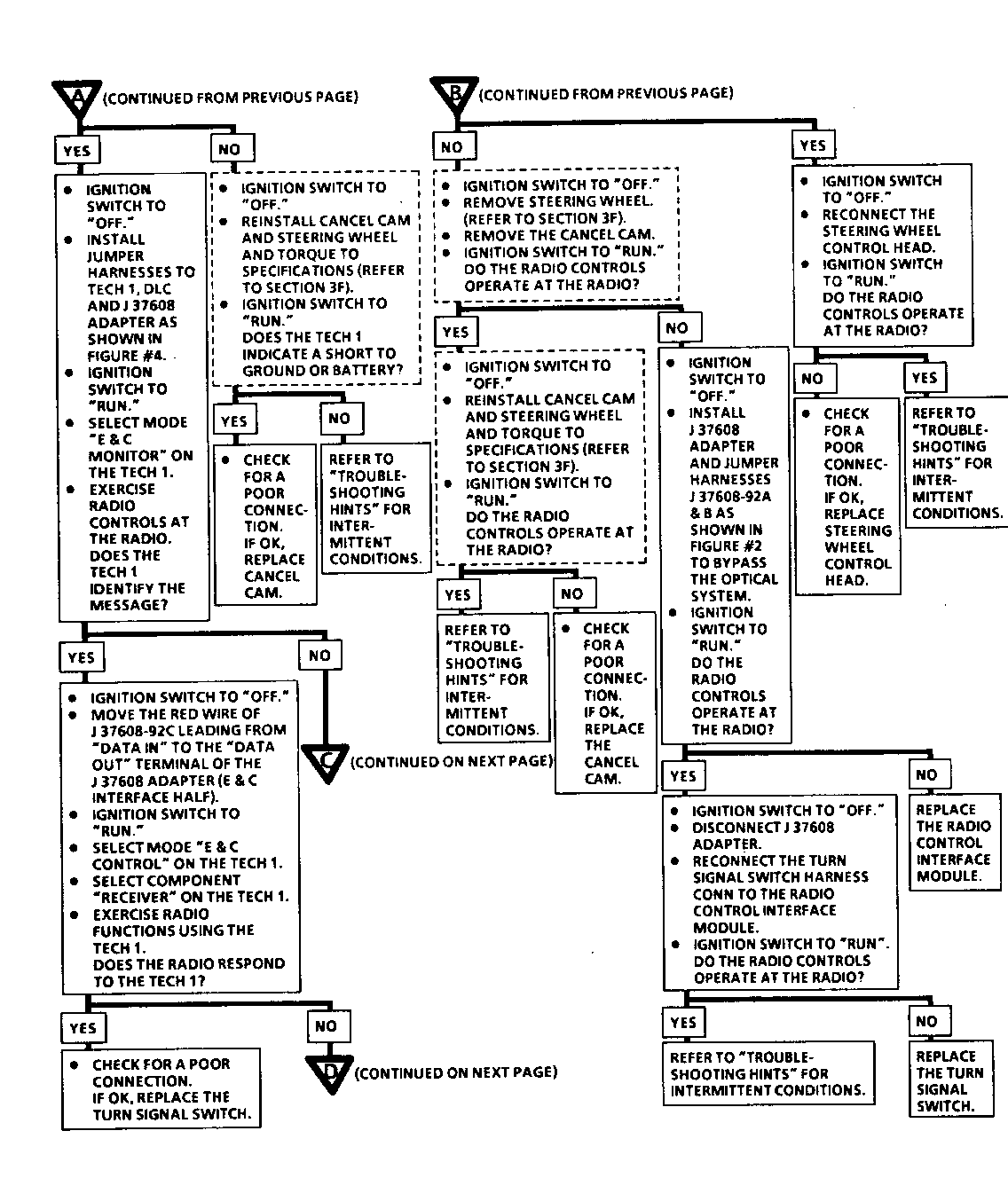
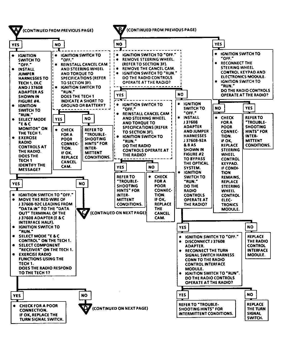
Chart 6 None of the functions operate from both the Steering Wheel Controls and the Radio Controls or none of the functions operate from the Steering Wheel Controls and only some functions operate from the Radio Controls.
For the boxes "Replace the E&C Interface Module', before replacing the module - perform the same E&C Interface Module Power, Ground, and E&C data line checks as instructed above for chart 3.
If the SWC has HVAC commands and you respond Yes to - Ignition Switch off, Disconnect radio or receiver box, Ignition Switch in run, Does the TECH1 identify E&C Bus shorted to ground or battery: Before continuing, disconnect HVAC Control Assembly to verify that it is not causing the shorted E&C data bus. If so, service the HVAC Control Assembly, if not continue with the chart.
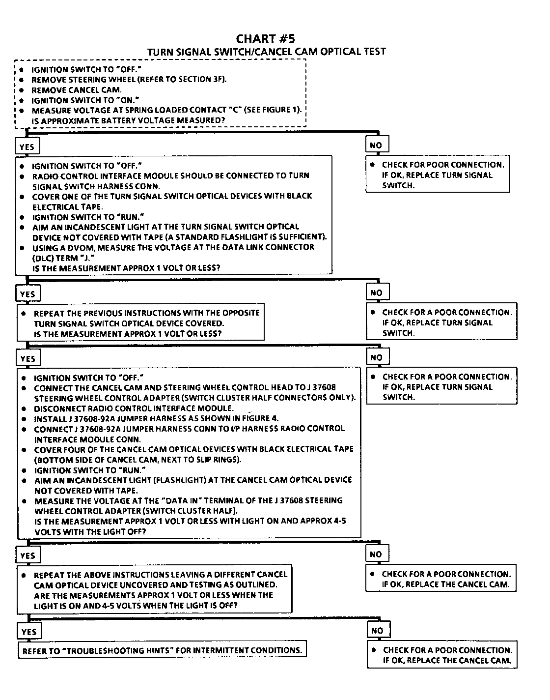
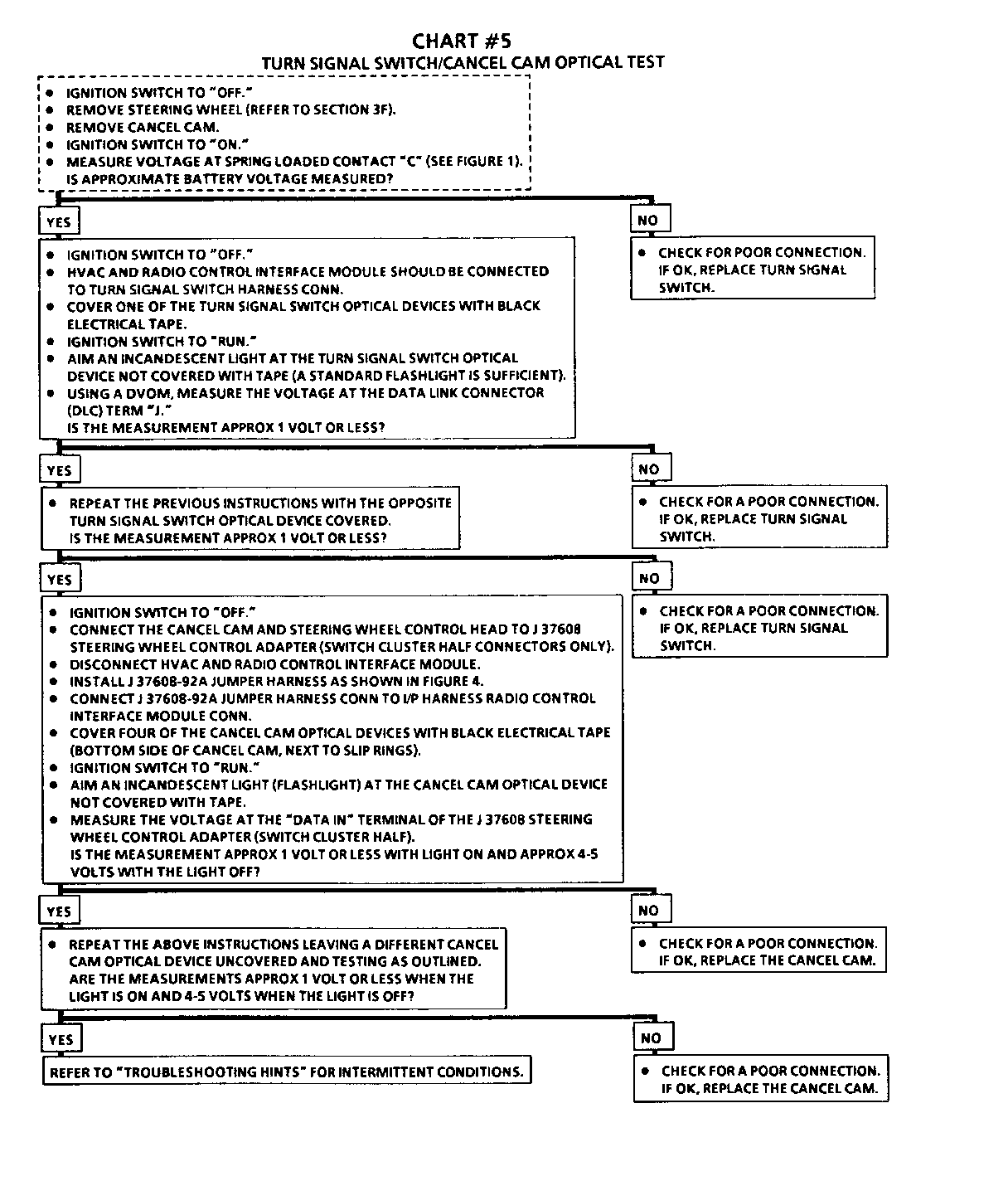
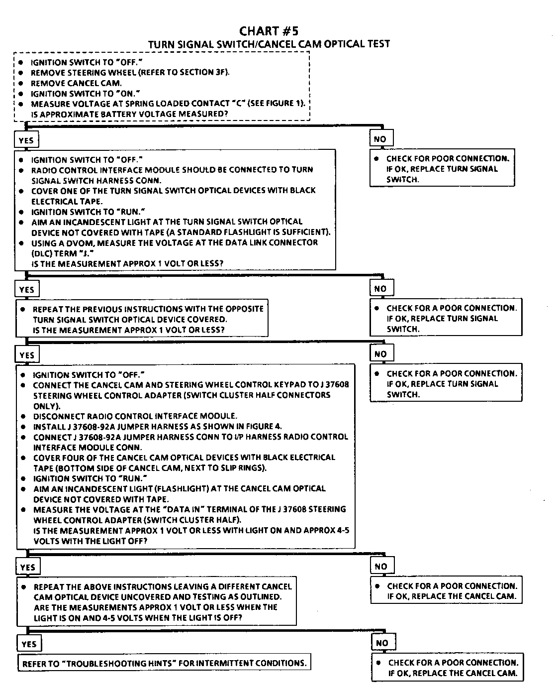
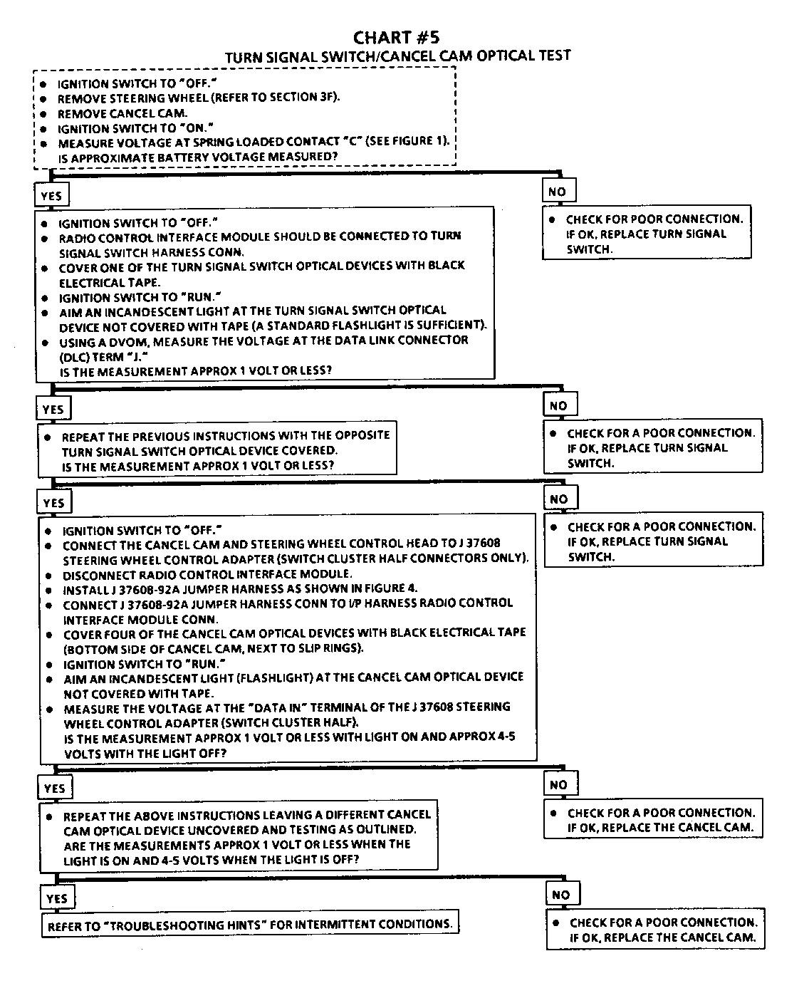
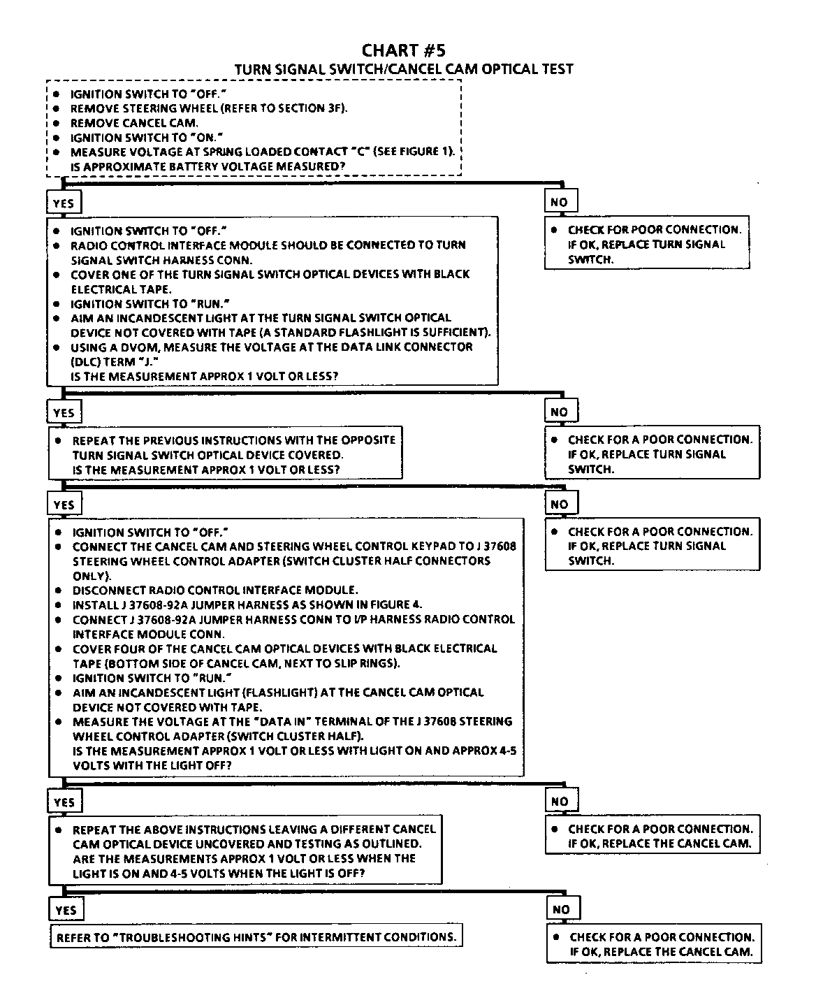
Turn Signal Switch / Cancel Cam Optical Test
Before performing the optical test, verify that battery voltage is present at the spring loaded brush in the turn signal switch. If not, replace the turn signal switch. Verify the ground spring loaded brush in the turn signal switch, that there is not an open circuit or shorted wire. Repair as needed. Refer to the vehicle service manual to determine the respective brushes.
Refer to Figures:
1-15 for the Pontiac "W" car. 16-30 for the Oldsmobile "W" car. 31-45 for the Buick "W" car. 46-60 for the Pontiac "A" car. 61-75 for the Buick "A" car.
General Motors bulletins are intended for use by professional technicians, not a "do-it-yourselfer". They are written to inform those technicians of conditions that may occur on some vehicles, or to provide information that could assist in the proper service of a vehicle. Properly trained technicians have the equipment, tools, safety instructions and know-how to do a job properly and safely. If a condition is described, do not assume that the bulletin applies to your vehicle, or that your vehicle will have that condition. See a General Motors dealer servicing your brand of General Motors vehicle for information on whether your vehicle may benefit from the information.
