SERVICE MANUAL UPDATE SEC. 6E3 REVISED CODE 17 CHART

Subject: SERVICE MANUAL UPDATE-SECTION 6E3 DRIVEABILITY AND EMISSIONS REVISED CODE 17 CHART
Models Affected: 1991-92 'C', 1992 'H' 3800 (VIN L)
This bulletin updates the Code 17 Diagnostic Chart and Facing Page in "Driveability And Emissions" Section 6E3 for 1992 Bonneville models equipped with the 3800 (VIN L) engine. This bulletin includes separate diagnostic charts and facing pages for use with "Type I" and "Type II" ignition systems. To ensure proper diagnosis and to avoid replacement of good parts, the type of system being diagnosed must be identified and the correct chart for the applicable system used.
The "Type I" ignition module is identified by 2 rows of coil towers and a single coil pack containing all 3 coils. "Type II" ignition modules have all 6 coil towers on the same side of the module and individually replaceable coil packs.
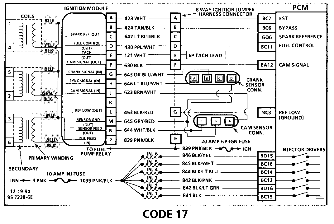
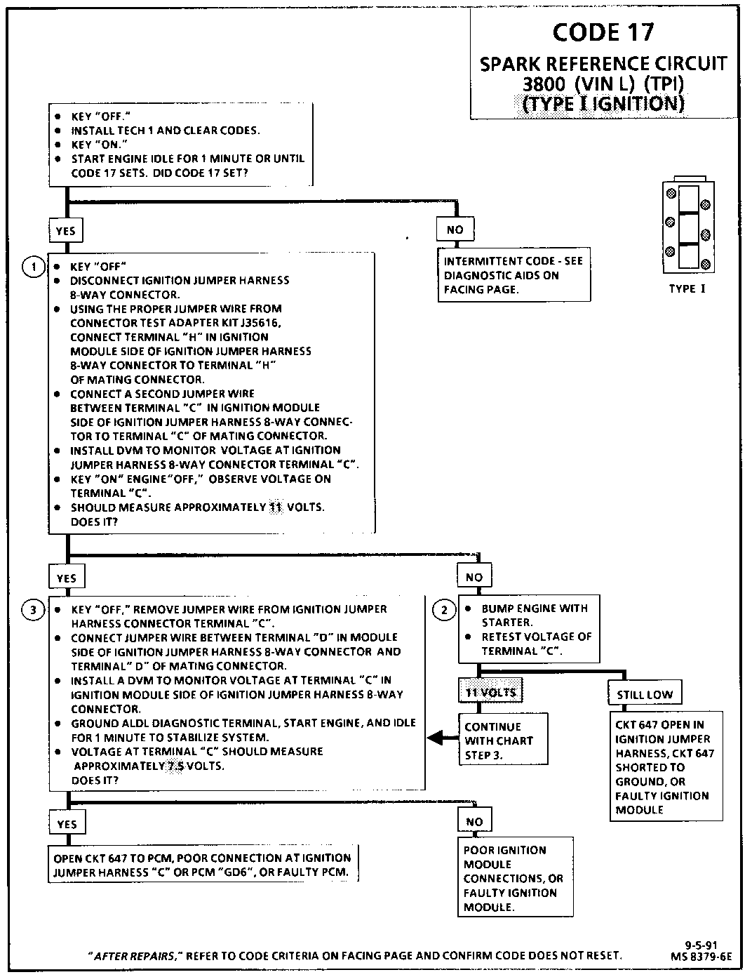
CODE 17 SPARK REFERENCE CIRCUIT (VIN L) (TPI) (TYPE I IGNITION) ------------------------------------------------------- Circuit Description:
The spark reference signal (CKT 647) is used by the PCM to improve ignition timing accuracy during crank and at engine speeds of up to 1200 rpm. The spark reference circuit allows the use of EST mode below 400 rpm, eliminating the need to utilize bypass mode during startup, and also allows the PCM to calculate true crankshaft position in 1/6 the time that use of the fuel control reference signal would permit.
During normal operation, the PCM uses the spark reference signal to control ignition timing until the engine speed exceeds 1200 rpm, at which time the fuel control reference signal (CKT 430) is used. When conditions for setting Code 17 exist, the fuel reference signal is used by the PCM to control EST. This condition will cause bypass mode to be used for ignition timing below 400 rpm and EST ignition timing to be degraded below 1200 rpm.
Code 17 will be set if:
o The engine is running. o The PCM detects 240 (80 crank revolutions) fuel control reference pulses, and no spark reference pulses. o Engine rpm is below 1200.
Code 17 does not illuminate the "Service Engine Soon" light.
Test Description: Number(s) below refer to circled number(s) on the diagnostic chart.
1. Verifies that CKT 647 is not shorted to ground or open in the ignition jumper harness.
2. If a window on the harmonic balancer is interfacing with the 18x hall effect switch, the ignition module will ground the spark reference signal. Starter may have to be bumped several times to obtain a voltage reading.
3. Voltage reading should be lower than that obtained with engine not running indicating a pulsed reference signal.
Diagnostic Aids:
An intermittent may be caused by a poor connection, rubbed through wire insulation, or a wire broken inside the insulation. Check for:
o Backed out connector terminals or broken down insulation in CKT 647.
o If connections and harness check OK, try monitoring voltage on CKT 647 with DVM while moving the related wiring harness and connectors with the engine idling. This may help to isolate the location of the malfunction.
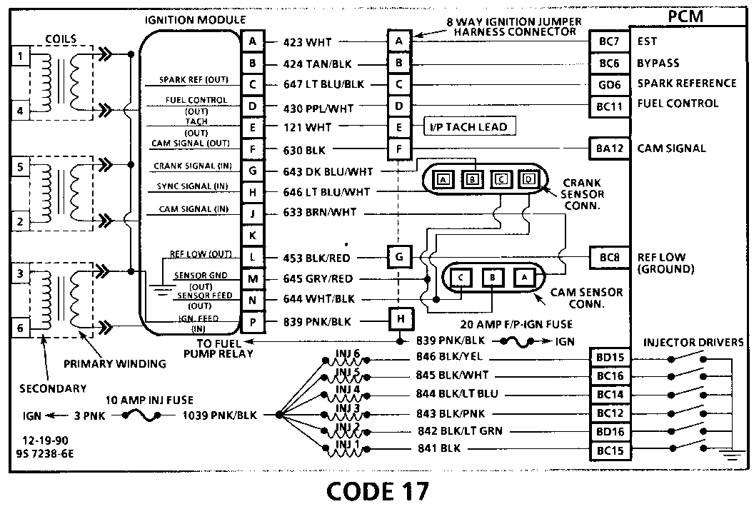
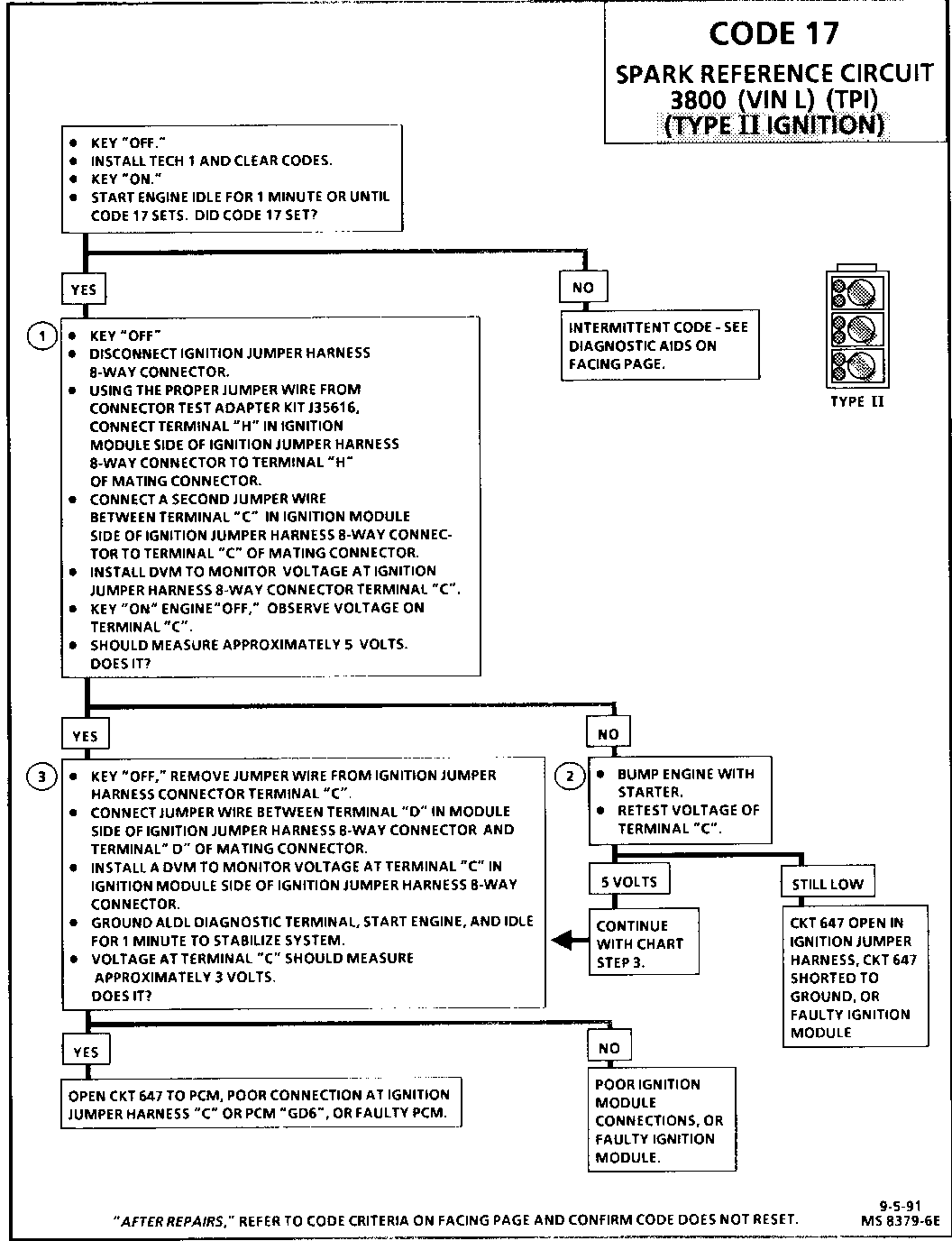
CODE 17 SPARK REFERENCE CIRCUIT 3800 (VIN L) (TPI) (TYPE II IGNITION) ------------------------------------------------------------- Circuit Description:
The spark reference signal (CKT 647) is used by the PCM to improve ignition timing accuracy during crank and at engine speeds of up to 1200 rpm. The spark reference circuit allows the use of EST mode below 400 rpm, eliminating the need to utilize bypass mode during startup, and also allows the PCM to calculate true crankshaft position in 1/6 the time that use of the fuel control reference signal would permit.
During normal operation, the PCM uses the spark reference signal to control ignition timing until the engine speed exceeds 1200 rpm, at which time the fuel control reference signal (CKT 430) is used. When conditions for setting Code 17 exist, the fuel reference signal is used by the PCM to control EST. This condition will cause bypass mode to be used for ignition timing below 400 rpm and EST ignition timing to be degraded below 1200 rpm.
Code 17 will be set if:
o The engine is running. o The PCM detects 240 (80 crank revolutions) fuel control reference pulses, and no spark reference pulses. o Engine rpm is below 1200.
Code 17 does not illuminate the "Service Engine Soon" light.
Test Description: Number(s) below refer to circled number(s) on the diagnostic chart.
1. Verifies that CKT 647 is not shorted to ground or open in the ignitionjuiingmper harness. ing 2. If a window on the harmonic balancer is interfacing with the 18x hall effect switch, the ignition module will ground the spark reference signal. Starter may have to be bumped several times to obtain a voltage reading.
3. Voltage reading should be lower than that obtained with engine not running indicating a pulsed reference signal.
Diagnostic Aids:
An intermittent may be caused by a poor connection, rubbed through wire insulation, or a wire broken inside the insulation. Check for:
o Backed out connector terminals or broken down insulation in CKT 647.
o If connections and harness check OK, try monitoring voltage on CKT 647 with DVM while moving the related wiring harness and connectors with the engine idling. This may help to isolate the location of the malfunction.


General Motors bulletins are intended for use by professional technicians, not a "do-it-yourselfer". They are written to inform those technicians of conditions that may occur on some vehicles, or to provide information that could assist in the proper service of a vehicle. Properly trained technicians have the equipment, tools, safety instructions and know-how to do a job properly and safely. If a condition is described, do not assume that the bulletin applies to your vehicle, or that your vehicle will have that condition. See a General Motors dealer servicing your brand of General Motors vehicle for information on whether your vehicle may benefit from the information.
