SERVICE MANUAL UPDATE-SEC. 10 DOORS/LOCKS/WINDOWS SERV. PROC

Subject: SERVICE MANUAL UPDATE - SECTION 10- DOORS/LOCKS/WINDOWS SERVICE PROCEDURES Models (REVISED) Affected: 1992-93 BONNEVILLE MODELS
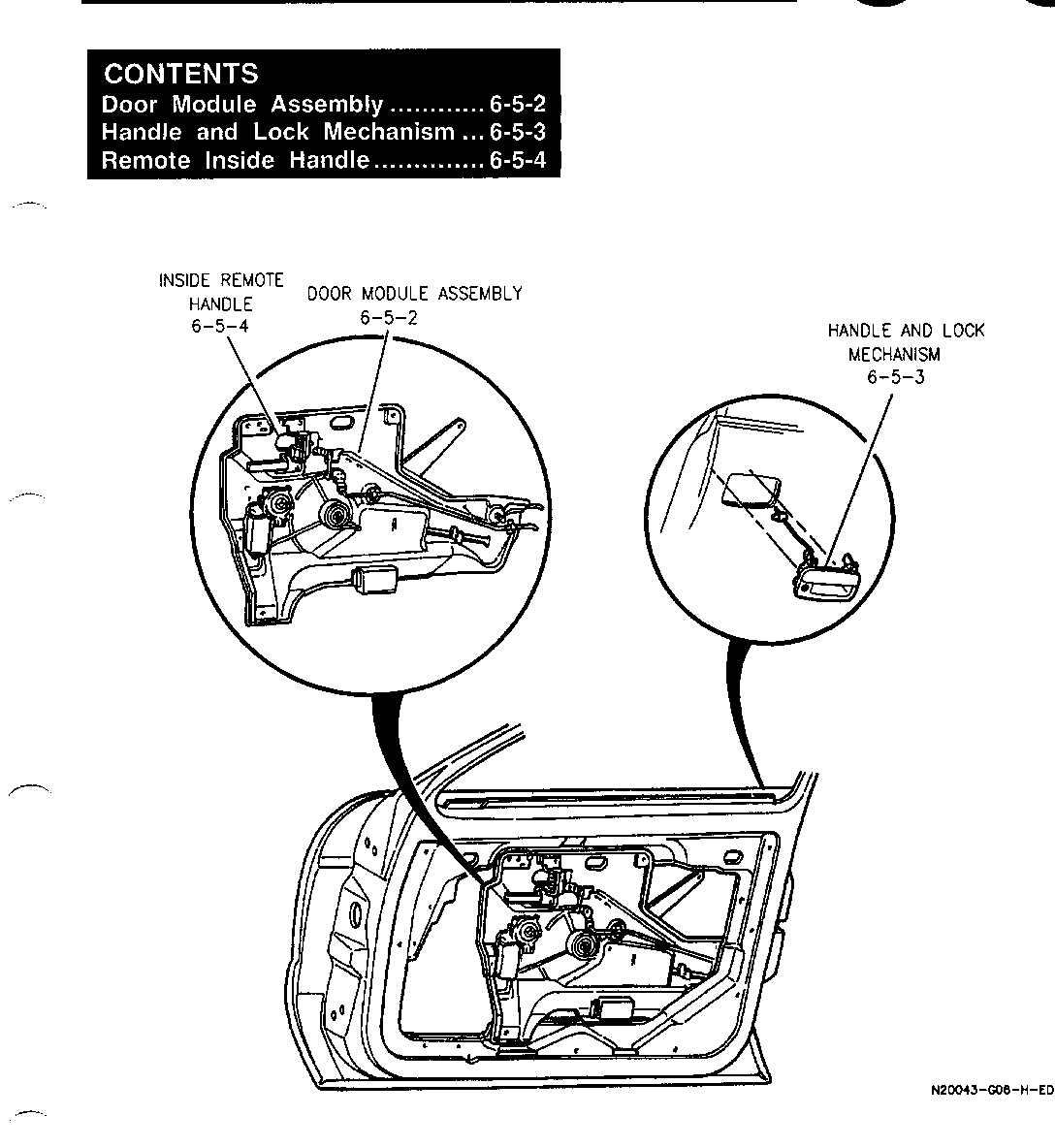
FRONT DOOR LOCKS: 1992 Bonneville SE Service Manual, page 6-5 1992 Bonneville SSE/SSEI Service Manual, page 6-5 1993 Bonneville SE/SSE/SSEI Service Manual, page 6-5
DOOR MODULE ASSEMBLY - REPLACEMENT: 1992 Bonneville SE Service Manual, page 6-5-2 1992 Bonneville SSE/SSEI Service Manual, page 6-5-2 1993 Bonneville SE/SSE/SSEI Service Manual, page 6-5-2
HANDLE AND LOCK MECHANISM - REPLACEMENT: 1992 Bonneville SE Service Manual, page 6-5-3 1992 Bonneville SSE/SSEI Service Manual, page 6-5-3 1993 Bonneville SE/SSE/SSEI Service Manual, page 6-5-3
REMOTE INSIDE HANDLE - REPLACEMENT: 1992 Bonneville SE Service Manual, page 6-5-4 1992 Bonneville SSE/SSEI Service Manual, page 6-5-4 1993 Bonneville SE/SSE/SSEI Service Manual, page 6-5-4
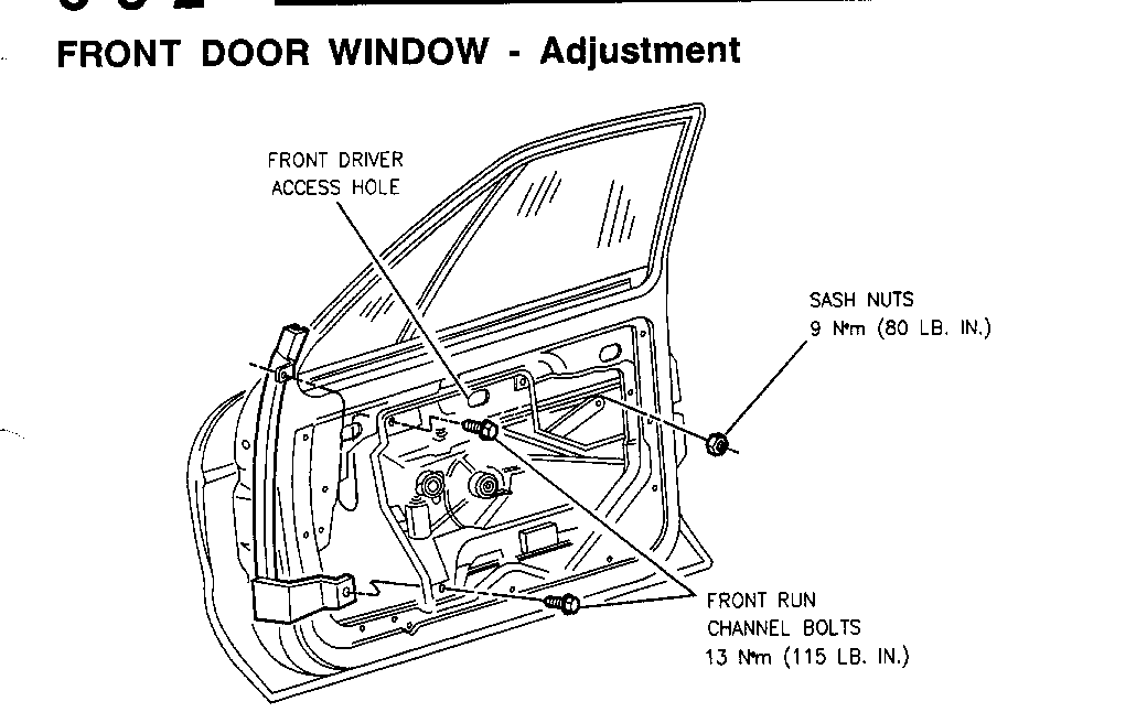
FRONT DOOR WINDOW - ADJUSTMENT: 1992 Bonneville SE Service Manual, page 6-6-2 1992 Bonneville SSE/SSEI Service Manual, page 6-6-2 1993 Bonneville SE/SSE/SSEI Service Manual, page 6-6-2
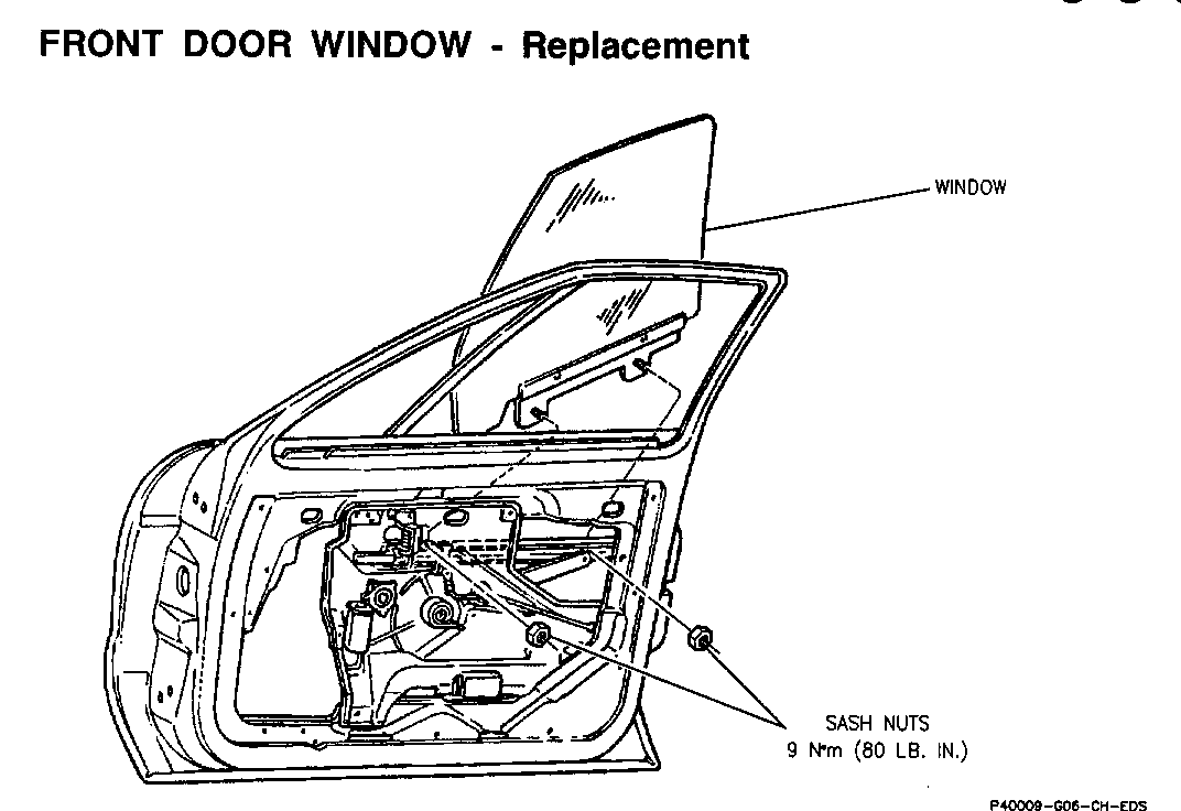
FRONT DOOR WINDOW - REPLACEMENT: 1992 Bonneville SE Service Manual, page 6-6-3 1992 Bonneville SSE/SSEI Service Manual, page 6-6-3 1993 Bonneville SE/SSE/SSEI Service Manual, page 6-6-3
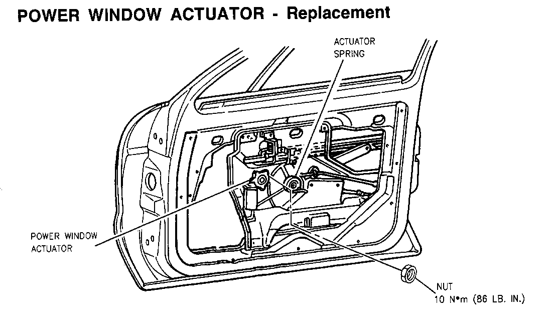
POWER DOOR WINDOW ACTUATOR - REPLACEMENT: 1992 Bonneville SE Service Manual, page 6-6-3 1992 Bonneville SSE/SSEI Service Manual, page 6-6-4 1993 Bonneville SE/SSE/SSEI Service Manual, page 6-6-4
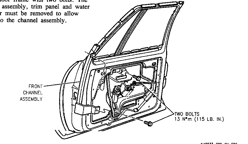
FRONT CHANNEL ASSEMBLY - REPLACEMENT: 1992 Bonneville SE Service Manual, page 6-6-5 1992 Bonneville SSE/SSEI Service Manual, page 6-6-6 1993 Bonneville SE/SSE/SSEI Service Manual, page 6-6-6
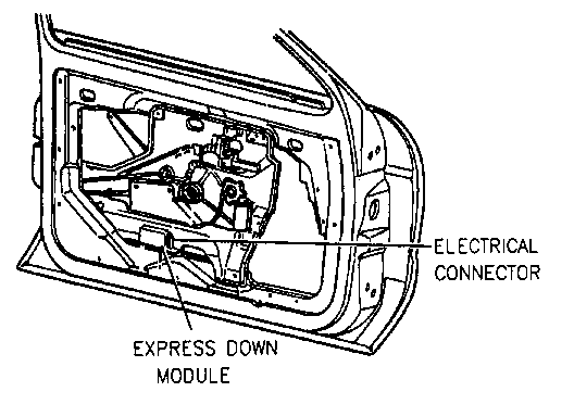
EXPRESS DOWN MODULE - REPLACEMENT: 1992 Bonneville SE Service Manual, page 6-6-6 1992 Bonneville SSE/SSEI Service Manual, page 6-6-7 1993 Bonneville SE/SSE/SSEI Service Manual, page 6-6-7
WINDOW SASH SLIDER - REPLACEMENT: 1992 Bonneville SE Service Manual, page 6-6-6 1992 Bonneville SSE/SSEI Service Manual, 6-6-7 1993 Bonneville SE/SSE/SSEI Service Manual, page 6-6-7
LOCK MECHANISM - REPLACEMENT: 1992 Bonneville SE Service Manual, page 7-5-2 1992 Bonneville SSE/SSEI Service Manual, page 7-5-2 1993 Bonneville SE/SSE/SSEI Service Manual, page 7-5-2
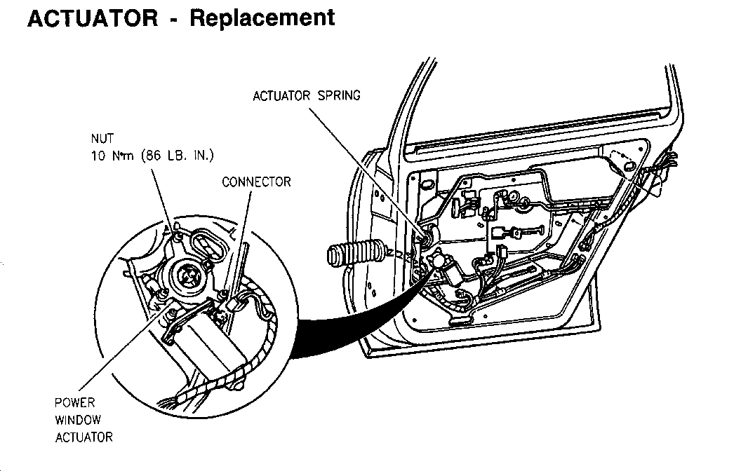
ACTUATOR - REPLACEMENT: 1992 Bonneville SE Service Manual, page 7-6-3 1992 Bonneville SSE/SSEI Service Manual, page 7-6-3 1993 Bonneville SE/SSE/SSEI Service Manual, page 7-6-2
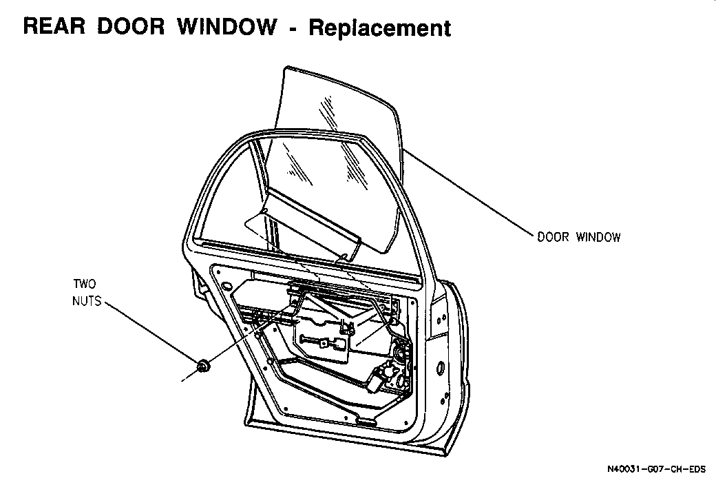
REAR DOOR WINDOW - REPLACEMENT: 1992 Bonneville SE Service Manual, page 7-6-3 1992 Bonneville SSE/SSEI Service Manual, page 7-6-4 1993 Bonneville SE/SSE/SSEI Service Manual, page 7-6-4
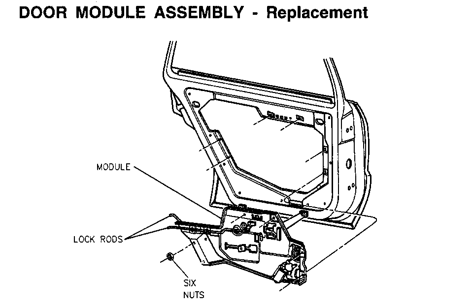
DOOR MODULE ASSEMBLY - REPLACEMENT: 1992 Bonneville SE Service Manual, page 7-6-5 1992 Bonneville SSE/SSEI Service Manual, page 7-6-6 1993 Bonneville SE/SSE/SSEI Service Manual, page 7-6-6
Please update your service manuals accordingly.
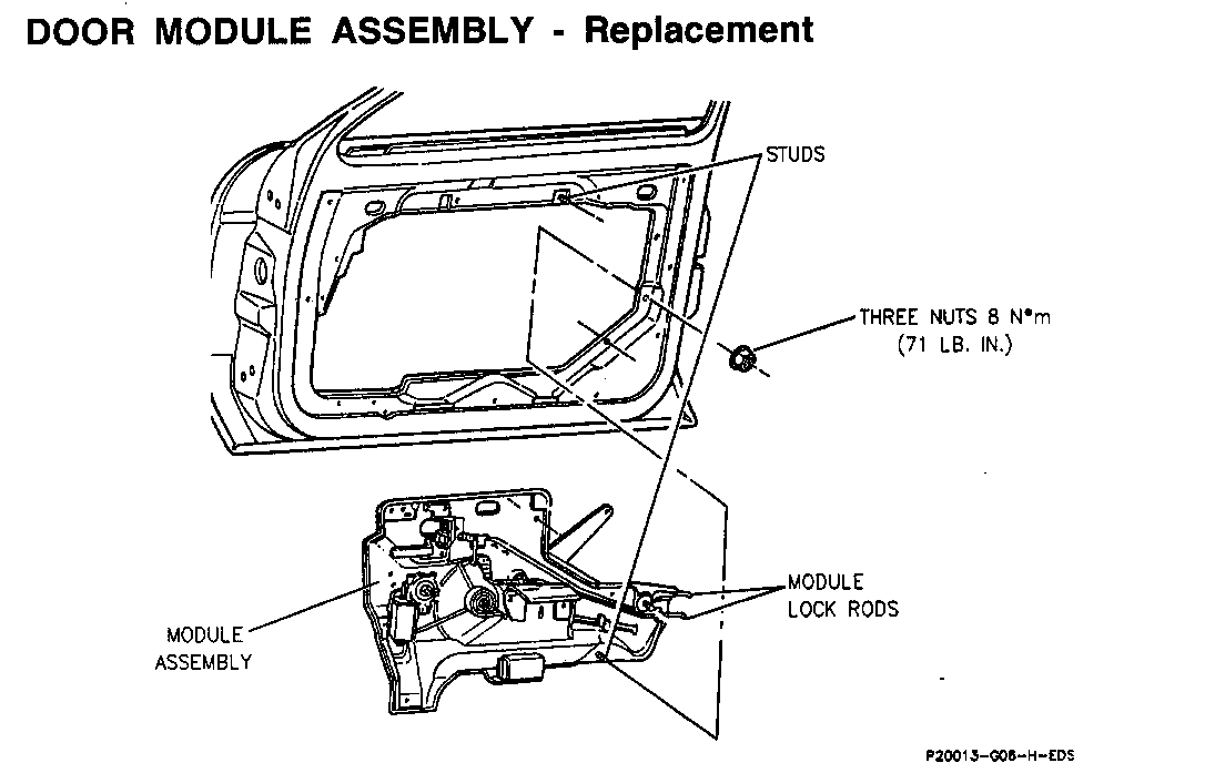
REMOVAL
1. Remove trim panel, water deflector, speaker and rear trim bracket. Tape glass to header.
2. Remove front run channel.
3. Disconnect wire connectors from latch and rose buds from panel.
4. Disconnect module lock rods from latch. Cut out and discard lock rod clips.
5. Remove upper nuts.
6. Remove module assembly.
INSTALLATION
NOTICE: Crossarms cannot be repaired. If damage occurs to crossarm assembly, replace module.
1. Install new lock rod clips to latch.
2. Load module assembly through access hole. Install upper nut and front run channel.
3. Install module lock rods to latch.
4. Connect wire connectors.
5. Adjust door window (see page 6-6-2).
6. Install speaker, water deflector, rear trim bracket and trim panel. Water deflector must adhere well with no wrinkles at bottom.
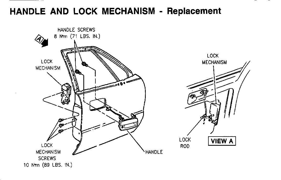
IMPORTANT: Do not operate lock or remove block-out plug prior to installation.
1. Remove trim panel, water deflector and rear run channel.
2. Disconnect lock rod. Discard lock rod clip.
3. Remove door handle screws and the handle.
4. Remove lock mechanism screws and the lock mechanism.
5. Disconnect electrical connector.
6. Reverse steps for installation. Install new lock rod clip to latch. Adjust lock rod and remove block-out plug.
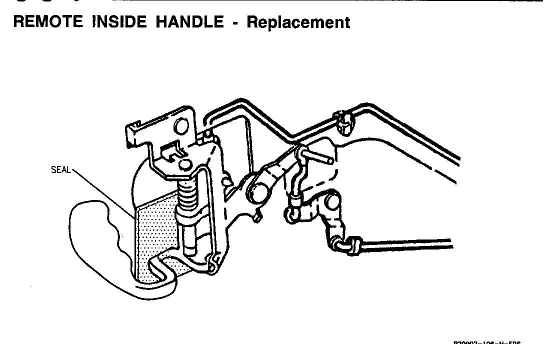
REMOVAL
1. Remove trim panel and water deflector.
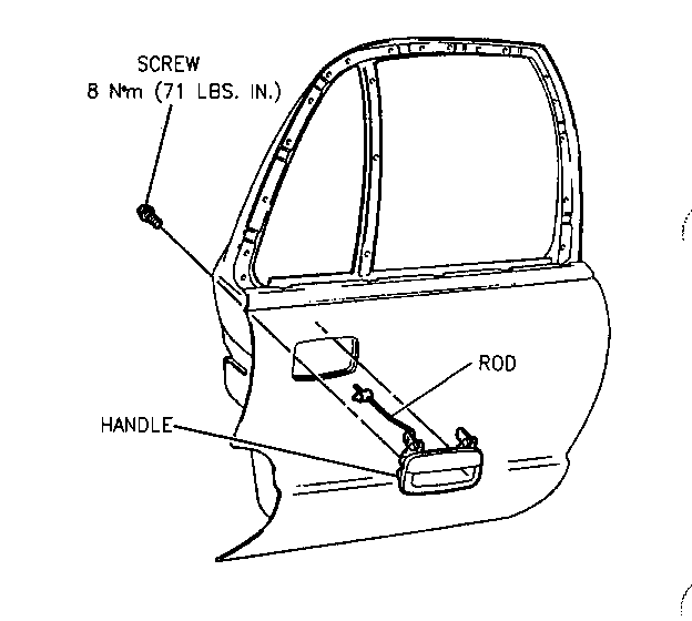
2. Remove handle-to-lock rod.
3. Remove short lock rod from bellcrank pin by crimping flat nut.
4. Using a3/16 inch drill bit, remove rivets.
5. Remove handle.
INSTALLATION
1. Install handle to door using 3/16 x 5/16 inch rivets. Ensure locating tabs are seated into slot in door panel prior to installing rivets.
2. Install short lock rod over bellcrank pin. Secure with push-on nut.
IMPORTANT: Ensure inside handle seal is in place prior to trim panel installation.
3. Install water deflector and trim panel.
1. Remove trim panel and water deflector.
2. Loosen front run channel bolts.
3. Loosen window to module sash nuts.
4. Move window upward into door header.
5. Grasp window and move it forward and upward into seal to assure full engagement of window to run channel.
6. Tighten window to module sash nuts.
7. Tighten front run channel bolts.
8. Cycle window up and down to check operation.
9. Install water deflector and trim panel.
1. Remove: o Trim panel. o Upper part of water deflector. o Inner and outer belt strips.
2. Remove sash nuts.
3. Remove window through outboard side of door.
4. Reverse steps for installation. insure glass is in both front and rear channels.
1. Ensure window is 1 inch below full up position, then remove trim panel and water deflector.
CAUTION:
If door module assembly is removed from vehicle, relieve tension on actuator spring using tool J 33864 or equivalent. Fallure to relieve tension on actuator spring could cause the crossarm assembly to suddenly spring closed when removing power window actuator, resulting in personal injury.
2. Remove three retaining nuts.
3. Disconnect electrical connector.
4. Remove power window actuator.
5. Reverse steps for installation.
IMPORTANT: When installing actuator, ensure teeth on actuator align with teeth on crossarm assembly.
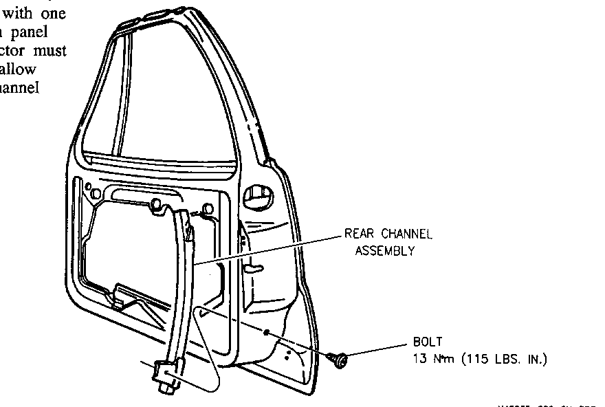
The front channel assembly is attached to the door frame with two bolts. The speaker assembly, trim panel and water deflector must be removed to allow access to the channel assembly.
The rear channel assembly is attached to the door frame with one screw. The trim panel and water deflector must be removed to allow access to the channel assembly.
1. Remove trim panel and water deflector.
2. Depress tang and slide tabs out of keyhole slots.
3. Disconnect electrical connector.
4. Remove module.
5. Reverse steps for installation.
REMOVAL
1. Remove trim panel, water deflector and door module assembly.
2. Place module in vise.
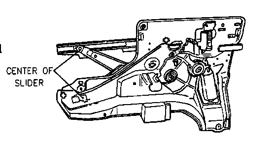
3. Drill out center of slider using a 3/16 inch drill bit.
4. Remove slider from door module.
INSTALLATION
1. Install slider into sash channel.
2. With positive restraint behind slider, peen rivet (part of new slider) with a hammer.
3. Install door module assembly, water deflector and trim panel.
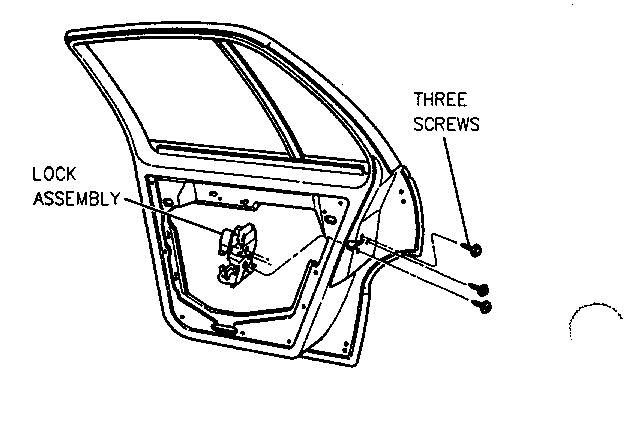
1. Remove trim panel and upper part of water deflector. Disconnect jumper harness connectors.
2. Disconnect lock rods.
3. Disconnect electrical connector.
4. Remove three screws and the lock assembly. Cut out and discard three lock rod clips.
5. Reverse steps for installation.
The outside handle is connected to the door with two bolts and a lock rod. The trim panel and the water deflector must be removed to allow access to the handle bolts. Adjust the lock rod before installing it to the latch.
1. Ensure window is 1 inch below full up position, then remove trim panel and water deflector.
CAUTION:
If door module assembly is removed from vehicle, relieve tension on actuator spring using tool J 38864 or equivalent. Failure to relieve tension on actuator spring could cause the crossarm assembly to suddenly spring closed when removing power window actuator, resulting in personal injury.
2. Remove trim panel, water deflector and inner and outer belt strips.
3. Remove three nuts.
4. Disconnect electrical connector and remove actuator.
5. Reverse steps for installation.
IMPORTANT: When installing actuator, ensure teeth on actuator align with teeth on crossarm assembly.
REMOVAL
1. Remove trim panel, upper part of water deflector and inner and outer belt strips.
2. Remove two sash nuts and loosen front run channel assembly bolt.
3. Remove window from door.
INSTALLATION
1. Install sash and guide to window, if removed.
2. Install window from outboard side of door as shown.
3. Install sash nuts.
4. Install inner and outer belt strips.
5. Adjust window (see page 7-6-3).
6. Install water deflector and trim panel.
REMOVAL
1. Remove trim panel, trim brackets and water deflector.
2. Tape window to header.
3. Disconnect lock rods from latch. Discard lock rod clips.
4. Disconnect wire hamess bundle and position out of way.
5. Remove upper and forward nuts on module and two nuts from window sash to module.
6. Remove module.
INSTALLATION
NOTICE: Crossarms cannot be repaired. If damage occurs to crossarm assembly, replace module.
1. Install new lock rod clips to latch, then install lock rods.
2. Install module to door.
3. Install upper and forward nuts.
4. Connect lock rods and hamess bundle.
5. Remove tape from window and install sash to module nuts. Adjust window (see page 7-6-3).
6. Install water deflector, trim brackets and trim panel.
General Motors bulletins are intended for use by professional technicians, not a "do-it-yourselfer". They are written to inform those technicians of conditions that may occur on some vehicles, or to provide information that could assist in the proper service of a vehicle. Properly trained technicians have the equipment, tools, safety instructions and know-how to do a job properly and safely. If a condition is described, do not assume that the bulletin applies to your vehicle, or that your vehicle will have that condition. See a General Motors dealer servicing your brand of General Motors vehicle for information on whether your vehicle may benefit from the information.
