Tech - Frt Seat Adjuster Sw Trim Plate Detaches from Seat;Seat Chucks/Rocks

| Subject: | Technical -- Front Seat Adjuster Switch Trim Plate Detaches from Seat and/or Seat Chucks/Rocks (Glue Retaining Clips/Install Horizontal Drive Actuator/Drive Asm) |
| Models: | 1997-2000 Buick Park Avenue, Park Avenue Ultra |
This bulletin is being revised to update the "Correction for Seat Assembly Movement " (horizontal actuator assembly replacement) portion of this bulletin. Please discard Corporate Bulletin Number 73-16-14A (Section 10 -- Body).
Condition
Some customers may comment that the front seat adjuster switch trim plate has become detached from the seat and/or the driver and/or passenger seat chucks/rocks or moves forward upon braking and rearward upon acceleration.
Cause
Detachment of the switch plate assembly may be caused by the retaining clips becoming detached from the switch plate. In some instances, the existing clips may not sufficiently retain the switch plate.
The movement or chuck/rock of the seat assembly may be caused by looseness in the horizontal actuator/drive portion of the seat adjuster frame assembly.
Correction for Switch Plate Separation (1997-98 Park Avenue, Park Avenue Ultra Models)
Glue the retaining clips, P/N 12457175, to the switch plate to correct a loose switch plate condition. The procedure for gluing the clips is outlined below. In some instances, the existing clips may not sufficiently retain the switch plate. When this condition exists, an additional clip, P/N 12457174 (barrel clip), must be added. The procedure for installing the barrel clip is outlined below.
Loose Switch Plate Repair Procedure
- Remove the switch plate. Refer to the Seat sub-section of the Service Manual.
- If the switch plate retaining clips separate from the switch plate, retrieve them from the holes in the seat pan.
- Install the clips to the switch plate using Goodwrench Instant Gel Adhesive or equivalent to retain the clips.
- Install the switch plate to the seat pan. Refer to the Seat sub-section of the Service Manual.
Barrel Clip Installation Procedure
Notice: The locator posts and switch-to-plate retaining tabs break easily.
- Remove the switch plate. Refer to the Seat sub-section of the Service Manual.
- Remove the switches from the switch plate, using a flat bladed tool to release the retaining tabs.
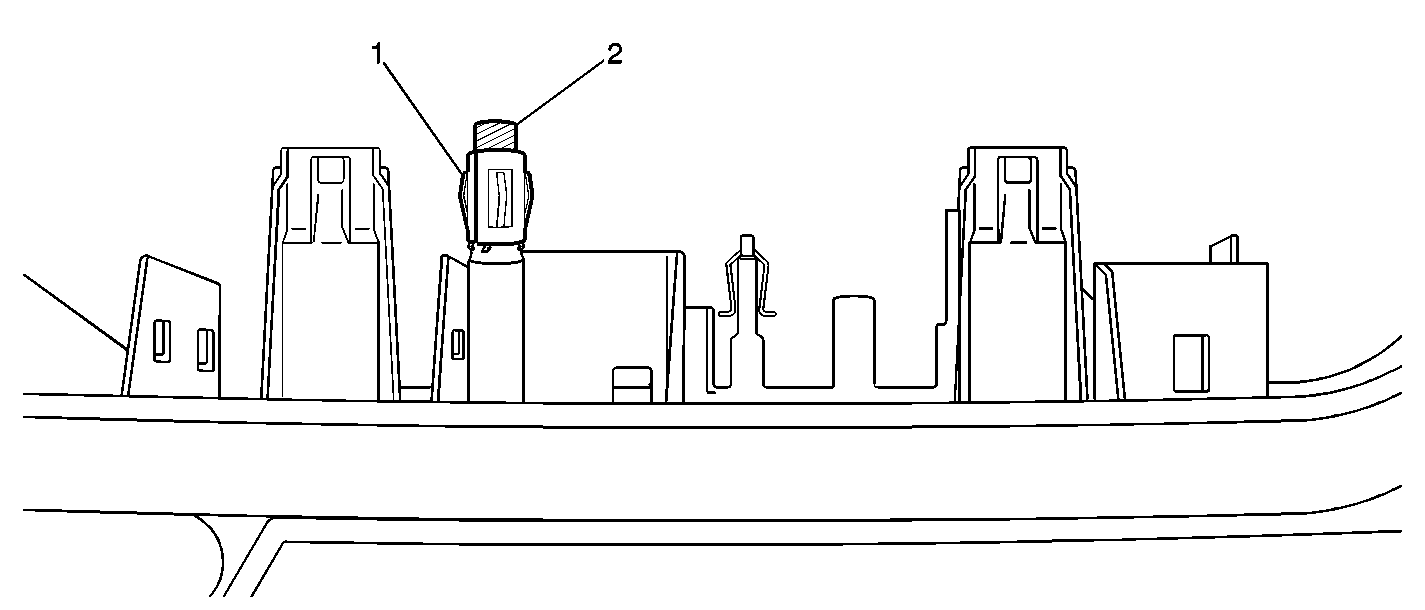
- Use a 5/16-24 die to thread the upper rear locator post (2) onto the switch plate. Thread the upper rear locator post down to the switch retaining tab or "rib". The die may be driven by hand or with a socket if necessary.
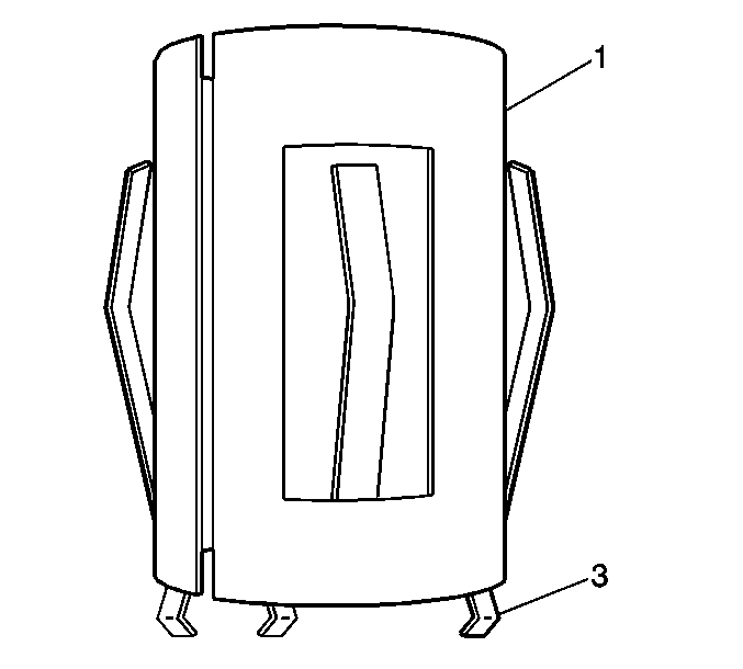
- Install the tubular speed clip (1), P/N 12457174, onto the threaded locator post (2) with the barbed end (3) of the clip facing the switch plate. Install the tubular speed clip (1) onto the locator post until the clip bottoms on the locator post.
- Glue the tubular speed clip (1) onto the locator post using Goodwrench Instant Gel Adhesive, or equivalent.
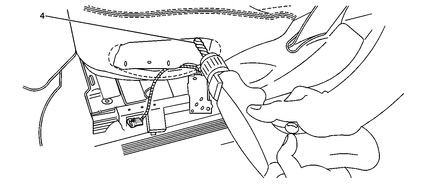
- Use a 3/8 inch drill bit to drill out the upper rearward locator hole (4) in the seat pan.
- Install the seat switches to the switch plate.
- Install the switch plate to the seat pan. Refer to the Seat sub-section of the Service Manual.


Caution: The front seat pan contains fiberglass. Use appropriate service precautions when working with fiberglass (i.e. gloves, safety glasses).

Parts Information
Part Number | Description |
|---|---|
12457174 | Speed Clip |
12457175 | Clip Fastener |
Parts are currently available from GMSPO.
Warranty Information
For vehicles repaired under warranty, use:
Labor Operation | Description | Labor Time |
|---|---|---|
C6488 | RH Side Switch Plate-Remove and Install | 0.3 hr |
C6489 | LH Side Switch Plate-Remove and Install | 0.3 hr |
ADD | To Modify Switch Plate and Install Barrel Clip - Each Side | 0.1 hr |
Correction for Seat Assembly Movement or Chucks/Rocks (1997-2000 Park Avenue, Park Avenue Ultra Models)
A design change to the horizontal actuator assembly has been made. Service parts have been released and are now available. Replace the driver and/or passenger seat adjuster horizontal actuator assembly with the following procedure.
However, in diagnosing the above listed vehicles, it is important not to overlook other obvious repairs prior to replacing the horizontal actuator assembly on the seat adjuster frame.
Diagnosis
- Verify that both rear seat-to-floorpan attaching bolts are not loose. If one or both of the bolts are loose, loosen both bolts, and with someone sitting in the seat, tighten the outer bolt first then the inner bolt in order to secure the seat to the floorpan.
- Verify that the front adjuster attachment hooks are properly engaged to the floorpan. Check the seat for a rocking condition. If the condition is corrected, no further repair is necessary. If the condition persists, proceed to the removal procedure.
Tighten
Tighten the bolts to 35 N·m (26 lb ft).
Removal Procedure
- Prior to removing the seat assembly:
- Remove the seat assembly.
- On vehicles equipped with memory seats:
- Place the seat assembly upside down with the seat back to the front on a clean protected surface.
- Disconnect the electrical connector from the horizontal drive actuator.
- On vehicles equipped with memory seats, disconnect the electrical connector from the horizontal drive actuator.
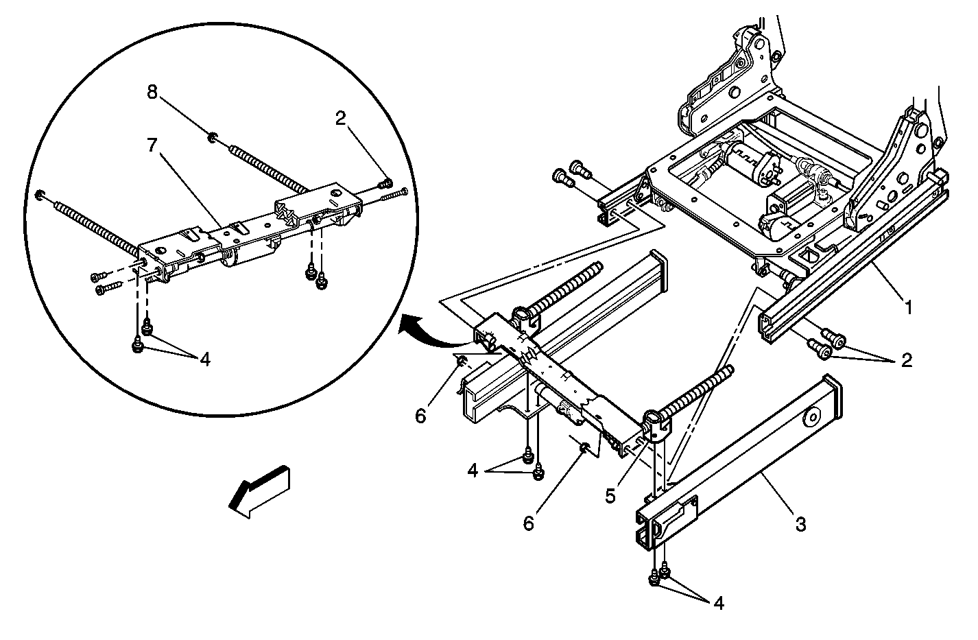
- Remove the horizontal nut cage bolts (4) from the horizontal drive actuator assembly (7). There are 4 per assembly, (the outer rails (3) will slide back.)
- Remove the horizontal drive bolts (2) from the horizontal drive actuator assembly (7). There are 4 per assembly.
- Separate the inner rails (1) and the horizontal drive actuator assembly (7) slightly in order to disengage the horizontal drive actuator assembly from the seat adjuster frame assembly.
- Remove the horizontal drive assembly (7) by pulling forward.
- Remove the two nylon bushings (8) from the "L" bracket on the inner rail.
| • | Position the vertical travel fully up. |
| • | Position the headrest fully down. |
| • | Position the recliner within approximately five degrees of fully forward. |
| • | Position the inner seat adjuster rail even with the outer seat adjuster rail. |
Refer to the Seat sub-section of the Service Manual.
| • | Place the driver's seat assembly right side up on a clean protected surface. |
| • | Remove the two front screws from the memory seat module bracket using a 90 degree screwdriver. |

This connector consists of a green wire and a beige wire.
Note which wire corresponds to which connector pin in the actuator.
Installation Procedure
- Lightly lubricate two new nylon bushings with grease.
- Install the two new nylon bushings (8) into the "L" bracket on the inner rail.
- Ensure that both horizontal nut cages (5) are threaded all the way down the lead screws to the horizontal drive housing. Install the horizontal drive actuator assembly.
- On vehicles equipped with memory seats, ensure the memory module bracket slides into the slots of the horizontal drive actuator assembly.
- Insert the horizontal lead screw ends into the nylon bushings.
- Install the two horizontal drive nuts (6) into the two recesses located on the inboard side of the horizontal drive housing. Install the horizontal drive bolts (2). There are 4 per assembly.
- Slide the outer rails (3) over the inner rails (1). Align the horizontal nut cages (5) with the nut brackets on the outer rails.
- Install the horizontal nut cage bolts (4). There are 4 per assembly.
- On vehicles equipped with memory seats, connect the electrical connector to the horizontal drive actuator.
- Lubricate the lead screw with grease.
- Power the seat adjuster assembly to the full forward position by using fused jumpers to apply battery positive voltage at the beige wire pin of the horizontal drive actuator connector body and battery ground to the green wire pin. Make sure the adjuster bottoms on the housing.
- Power the seat adjuster assembly back to the full rearward position by reversing the fused jumper connections made in Step 11. Ensure the front end of the inner rails are even with the front end of the outer rails. This position is approximately 20 mm (¾ inch) forward of full rear seat travel.
- Connect the electrical connector to the horizontal drive actuator.
- Place the seat in an upright position. Install the two front screws to the memory seat module bracket.
- Install the seat into the vehicle. Refer to the Seat Replacement section of the Service Manual.
- Check the power seat adjuster for proper operation.
The large flange must be on the side facing the horizontal drive actuator.
Tighten
Tighten the bolts to 18 N·m (13 lb ft).
Tighten
Tighten the bolts to 18 N·m (13 lb ft).
| • | Ensure that the front adjuster attachment hooks are properly engaged to the floorpan. |
| • | Install the outboard rail first to avoid unparalleled rails. |
| • | Ensure the inboard rail bolt has a washer present. |
Parts Information
Part Number | Description |
|---|---|
88893019 | Actuator Asm, D/Seat Adjuster Horizontal (Includes Two Nylon Bearings and Grease) |
88893020 | Actuator Asm, P/Seat Adjuster Horizontal (Includes Two Nylon Bearings and Grease) |
Parts are currently available from GMSPO.
Warranty Information
For vehicles repaired under warranty, use:
Labor Operation | Description | Labor Time |
|---|---|---|
C6300 | Actuator Asm, Front Seat Horizontal- Replace-Passenger | 0.7 hr |
C6301 | Actuator Asm, Front Seat Horizontal- Replace-Driver | 0.7 hr |
