GM Service Manual Online
For 1990-2009 cars only

Caution: This vehicle is equipped with Supplemental Inflatable Restraint (SIR). Refer to the Cautions in the On-Vehicle Service and the SIR Component and Wiring Location view in the Supplemental Inflatable (SIR) System before any performing service on or around SIR components or wiring. Failure to follow the Cautions could result in possible air bag deployment, personal injury, or otherwise unneeded SIR system repairs.

Notice: Always use the correct fastener in the proper location. When you replace a fastener, use ONLY the exact part number for that application.

The applicable service procedure will identify, where necessary, those fasteners that must be replaced after removal; or those fasteners that require the use of thread locking compound or thread sealant.

UNLESS OTHERWISE SPECIFIED, do not use supplemental coatings (paints, greases, or other corrosion inhibitors) on threaded fasteners or fastener joint interfaces. Generally, such coatings adversely affect the fastener torque and the joint clamping force, and may damage the fastener.

When you install fasteners, use the correct tightening sequence and specifications.

Following these instructions can help you avoid damage to parts and systems.

Notice: Use the correct fastener in the correct location. Replacement fasteners must be the correct part number for that application. Fasteners requiring replacement or fasteners requiring the use of thread locking compound or sealant are identified in the service procedure. Do not use paints, lubricants, or corrosion inhibitors on fasteners or fastener joint surfaces unless specified. These coatings affect fastener torque and joint clamping force and may damage the fastener. Use the correct tightening sequence and specifications when installing fasteners in order to avoid damage to parts and systems.

General Description

The fuel supply is stored in the fuel tank. An electric fuel pump, attached to the fuel sender (inside the fuel tank) pumps fuel through an in-line filter to the fuel injection system. The fuel pump is designed to provide fuel at a pressure above the regulated pressure needed by the fuel injectors. A fuel pressure regulator keeps fuel available to the fuel injectors at a regulated pressure. Unused fuel is returned to the fuel tank by a separate pipe. For further information on the fuel injection system, refer to Fuel Metering System Component Description .

Unleaded fuel must be used with all gasoline engines for proper emission control system operation. Using unleaded fuel will also decrease spark plug fouling and extend engine oil life. Leaded fuel can damage the emission control system, and its use can result in loss of emission warranty coverage.

All vehicles with gasoline engines are equipped with an evaporative emission system that minimizes the escape of fuel vapors to the atmosphere. For information regarding this system, refer to: Evaporative Emission Control System Diagnosis .

On-Board Refueling Vapor Recovery System (ORVR)

The On-Board Refueling Vapor Recovery System (ORVR) is an onboard vehicle system to recover fuel vapors during the vehicle re-fueling operation. The flow of liquid fuel down to the fuel tank filler neck provides a liquid seal. The purpose of (ORVR) is to prevent re-fueling vapor from exiting the fuel tank filler neck.

The ORVR components include:

    • Fuel Tank
    • Fuel Tank Filler Pipe
    • EVAP Canister
    • Vapor Lines
    • Check Valve
    • Modular Fuel Sender (fuel tank pressure sensor located on modular fuel sender cover)
    • Fuel Limiter Vent Valve (FLVV)
    • Pressure Vacuum Relief Valve
    • Vapor Recirculation Line
    • Variable Orifice Valve

The On-board Refueling Vapor Recovery System (ORVR) is an onboard vehicle system designed to recover fuel vapors during the vehicle refueling operation. The flow of liquid fuel down the filler neck provides a liquid seal which prevents vapor from leaving the fuel system by transporting vapor to the EVAP canister for use by the engine. Listed below are the ORVR system components with a brief description of their operation:

  1. Fuel Tank - contains the modular fuel sender, fuel limiter vent valve, and 3 rollover valves.
  2. Fuel Filler Pipe - the pipe which carries fuel from the fuel nozzle to the fuel tank.
  3. EVAP Canister - the EVAP canister receives refueling vapor from the fuel system, stores the vapor and releases the vapor to the engine upon demand.
  4. Vapor Lines - transports fuel vapor from the tank assembly to the EVAP canister.
  5. Check Valve - the check valve limits fuel "spitback" from the fuel tank during the refueling operation by allowing fuel flow only into the fuel tank. This check valve is located at the bottom of the fuel filler pipe.
  6. Modular Fuel Sender Assembly - this assembly pumps fuel to the engine from the fuel tank.
  7. Fill Limiter Vent Valve (FLVV) - this valve acts as a shutoff valve located in the fuel tank and has the following functions:
  8. • Controls the fuel tank fill level by closing the primary vent from the fuel tank
    • Prevents fuel from exiting the fuel tank via the vapor line to the canister
    • Provides fuel-spillage protection in the event of a vehicle rollover by closing the vapor path from the tank to the EVAP canister
  9. Pressure/Vacuum Relief Valve - the pressure/vacuum relief valve provides venting of excessive fuel tank pressure and vacuum. The valve is located in the fuel filler neck on a plastic fuel tank.
  10. Vapor Recirculation Line - The vapor recirculation line is used to transport vapor from the fuel tank to the top of the fill pipe during the refueling to reduce vapor loading to the Enhanced EVAP canister.
  11. Variable Orifice Valve - The variable orifice valve regulates the amount of vapor allowed to enter the vapor recirculation line.

Fuel Tank


Object Number: 155114  Size: SH

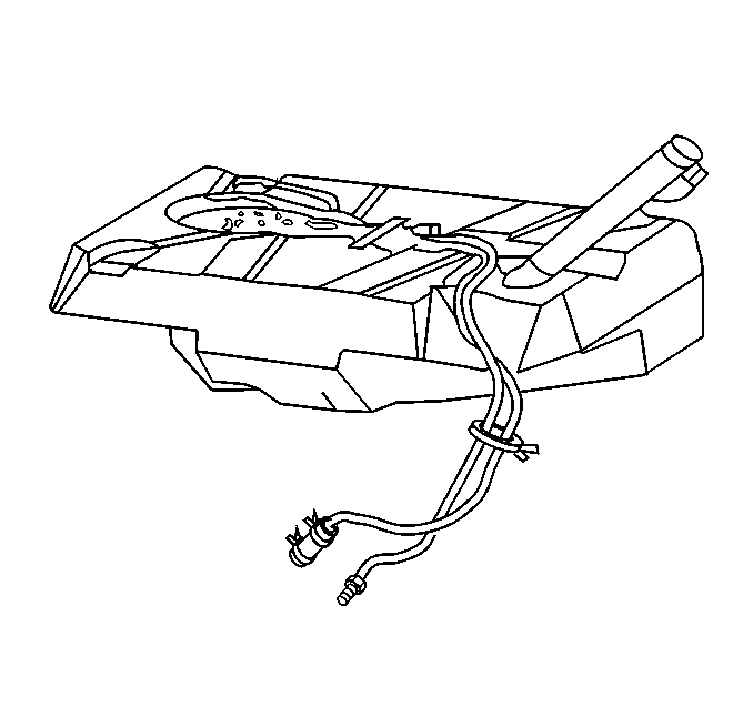
The fuel tank is used to store fuel for the vehicle. The tank is located in the rear of the vehicle and is held in place by two straps that are attached to the underbody. The fuel tank is made of plastic and is coated internally with a special corrosion inhibitor. Due to the internal coating of the fuel tank, the fuel tank is not repairable. The fuel tank shape includes a reservoir in order to maintain a constant supply of fuel around the fuel pump strainer during low fuel conditions and aggressive vehicle maneuvers.

The tank also contains a fuel vapor vent valve with roll-over protection. The vent valve also features a two phase vent calibration which increases fuel vapor flow to the canister when operating temperatures increase the tank pressure beyond an established threshold.

The fuel tank contains 3 rollover valves that prevents fuel from entering the fuel pipes in the event of a vehicle rollover. The rollover valves are not repairable.

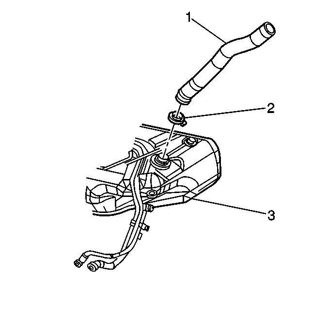
Fuel Tank Filler Pipe


Object Number: 104599  Size: SH
(1)Fuel Tank Filler Pipe
(2)Fuel Tank Filler Pipe Clamp
(3)Fuel Tank

The fuel tank filler pipe carries dispensed fuel from the fuel nozzle to the fuel tank.

In order to prevent refueling with leaded fuel, the fuel tank filler pipe has a built-in restrictor and deflector.

A fuel tank filler pipe check-valve is attached to the fuel tank filler pipe and extends from the fuel tank inlet to the reservoir. The fuel tank filler pipe check-valve is located inside the fuel tank filler pipe check-valve tube and prevents fuel from splashing back out of the fuel tank filler pipe during re-fueling.

Fuel Tank Filler Pipe Cap


Object Number: 211140  Size: SH

Notice: If a fuel tank filler pipe cap requires replacement, use only a fuel tank filler pipe cap with the same features. Failure to use the correct fuel tank filler pipe cap can result in a malfunction of the fuel system. A loose or incorrect fuel tank filler pipe cap can set a DTC.

The fuel tank filler pipe is equipped with a screw-type fuel tank filler pipe cap. A built-in ratchet-type torque limiting device prevents overtightening. In order to install the cap, the cap must be turned clock-wise until a clicking noise is heard. This signals that the correct torque has been reached and the cap is fully seated. A fuel filler cap that is not fully seated can cause a malfunction in the emission system.

The fuel tank filler pipe cap has a pressure relief and vacuum relief. The fuel tank filler pipe cap has a tether connected to the fuel tank filler pipe.

Modular Fuel Sender Assembly


Object Number: 188361  Size: SH
(1)Fuel Tank Pressure Sensor
(2)Fuel Pipes
(3)Fuel Pump
(4)External Fuel Sender Strainer
(5)Fuel Level Sensor Assembly
(6)Fuel Sender Cover

The modular fuel sender assembly is attached to the top of the fuel tank, and extends from the top of the fuel tank to the bottom.

The modular fuel sender assembly consists of the following major components: a fuel sender cover assembly, fuel pipes (above cover), a fuel pump, a fuel pump strainer, a fuel pump reservoir, an external fuel sender strainer, a ceramic card fuel level sensor assembly, and a fuel tank pressure sensor.

The fuel level sensor assembly consists of the float, the wire float arm, and the rheostat. The fuel level is sensed by the position of the float and float arm, which operates the rheostat. As the float position changes, the amount of current passing through the rheostat varies, thus changing the gauge reading on the instrument panel.

The modular fuel sender assembly mounts to the opening of the plastic fuel tank. The spring loaded reservoir. The design provides the following results:

    • Optimum fuel level in the integral fuel reservoir during all fuel tank levels and driving conditions
    • Improved tank fuel level measuring accuracy
    • Improved coarse straining and added pump inlet filtering
    • More extensive internal fuel pump isolation for noiseless operation

Fuel Sender Fuel Flow


Object Number: 570222  Size: LF
(1)Fuel Feed
(2)Fuel Return
(3)Convoluted Fuel Tube (Flex Pipe)
(4)Secondary Umbrella Valve
(5)External Fuel Pump Strainer
(6)Fuel Flow from External Strainer
(7)Fuel Pump Strainer
(8)Fuel Pump

The modular fuel sender assembly maintains optimum fuel level in the reservoir (bucket). Fuel entering the reservoir (bucket) is drawn in by:

    • The first stage of fuel flow is through the external strainer.
        And/Or
    • The umbrella valve
        Or
    • The return fuel pipe, whenever the level of fuel is below the top of the reservoir.

The fuel pump used in this system is part of the fuel sender assembly. The fuel pump lower connector assembly prevents the transmission of vibration and noise generated by the pump to the fuel tank.

Fuel enters the lower inlet port (secondary umbrella valve located inside of lower inlet port) of the fuel pump after being filtered by the external fuel strainer, and the fuel pump strainer. The initial function of the pump is to fill the reservoir.

The second stage separates vapor from the fuel in the pump. This vapor separation maximizes hot fuel handling and permits the vapor to return to the fuel tank at lower pressure and temperature. By creating positive fuel pressure, the pump then discharges the liquid fuel into the third stage of the pump. The pump outlet allows the fuel volume to flow through a check valve into the fuel pump flex pipe. The check valve seat is molded inside the connector body. The check valve body and retainer are assembled into the connector body. The check valve restricts fuel back flow.

After the fuel pump flex pipe, the fuel exits the assembly through the fuel feed output fitting on the molded cover. The cover also contains a fuel return provision which connects to one of three hollow support pipes.

Quick-connect pipe end fittings are molded onto the cover of the modular unit for ease of unit removal from the fuel tank. These quick-connect end fittings allow fuel feed and fuel return.

Electrical power to the fuel pump enters the unit by way of a connector which is attached to the cover. An internal wire harness and connector assembly connects to the fuel pump and level sensor. The modular design adds additional functions that improve accuracy and ensure constant, steady fuel supply under all conditions. All components and subassemblies of the modular sender attach to a common cover and access the fuel tank through a single opening. The modular fuel sender assembly is spring loaded to the bottom of the fuel tank. This bottom referencing permits continuous fuel pickup and accurate fuel level sensing. The reservoir assembly is the lower section of the modular unit which encases the fuel pump. A retainer attaches to the top of the reservoir. Fuel is captured and maintained in reservoir at a level sufficient to submerge the fuel pump.

Fuel Tank Vapor Pressure Sensor


Object Number: 18839  Size: SH

The fuel tank pressure sensor is used to detect small leaks in the evaporative emission system. The fuel tank pressure sensor is a three wire strain gauge sensor much like that of the common GM MAP sensor. However, this sensor has very different electrical characteristics due to its pressure differential design. The sensor measures the difference between the air pressure (or vacuum) in the fuel tank and the outside air pressure. The sensor mounts at the top of the fuel tank. A three wire electrical harness connects it to the Powertrain Control Module (PCM). The PCM supplies a five volt reference voltage and ground to the sensor. The sensor will return a voltage between 0.1 and 4.9 volts. When the air pressure in the fuel tank is equal to the outside air pressure, such as when the fuel fill cap is removed, the output voltage of the sensor will be 1.3 to 1.7 volts. Refer to Evaporative Emission Control System Diagnosis for further information and diagnosis of the enhanced EVAP system.

Enhanced Evaporative Emission (EVAP) Service Port


Object Number: 21046  Size: SH

The enhanced EVAP service port is located in the evaporative purge hose located between the purge solenoid and the EVAP charcoal canister. The service port is identified by a green colored cap. The port contains a schrader valve and fittings to allow the connection of the J 41413 Evaporative Pressure/Purge Diagnostic Station. Refer to EVAP control system diagnosis for further information and diagnosis of the Enhanced EVAP system.

External Fuel Sender Strainer


Object Number: 191387  Size: SH
(1)External Fuel Sender Strainer

The function of the fuel sender strainer is filter contaminants and to wick fuel.

The life of the fuel sender strainer is generally considered to be that of the fuel sender. The fuel sender strainer is self-cleaning and normally requires no maintenance. Fuel stoppage at this point indicates that the fuel tank contains an abnormal amount of sediment or water, in which case the tank should be thoroughly cleaned. Refer to Fuel System Cleaning . If the fuel sender strainer is plugged, replace it with a new one.

Fuel Level Sensor Assembly


Object Number: 50562  Size: SH

The fuel level sender is a ceramic card assembly that consists of the float, the wire float arm, and the rheostat. The fuel level is sensed by the position of the float and float arm, which operates the rheostat.

The rheostat is mounted on the fuel sender and located in series with the voltage supply circuit from the fuel gauge. As the position of the float varies with fuel level, the rheostat produces a variable resistance between the fuel gauge. The fuel gauge converts this variable resistance into the fuel level reading display on the instrument panel.

An isolated circuit is used in this application. The isolated ground circuit uses a dedicated ground wire from the rheostat to the fuel sender connector. The isolated ground circuit is used to prevent erratic fuel level readings caused by a difference in voltage potential among vehicle ground points. An isolated ground terminal is connected electrically to one end of the ceramic card.
In-Line Fuel Filter


Object Number: 12628  Size: SH
(1)Fuel Filter Housing
(2)Fuel Filter Element

A fuel filter is used in the fuel feed pipe ahead of the fuel injection system. The fuel filter is mounted on the right side of the underbody. The fuel filter housing is constructed of steel with a quick-connect fitting at the inlet of the fuel filter and a threaded fitting at the outlet of the fuel filter. The filter element is made of paper and is designed to trap particles suspended in the fuel that may damage the injection system.

There is no service interval for in-line fuel filter replacement. Only replace the in-line fuel filter if it is restricted.

Nylon Fuel Pipes

Caution: In order to Reduce the Risk of Fire and Personal Injury:

   • If nylon fuel pipes are nicked, scratched or damaged during installation, Do Not attempt to repair the sections of the nylon fuel pipes. Replace them.
   • When installing new fuel pipes, Do Not hammer directly on the fuel harness body clips as it may damage the nylon pipes resulting in a possible fuel leak.
   • Always cover nylon vapor pipes with a wet towel before using a torch near them. Also, never expose the vehicle to temperatures higher than 115°C (239°F) for more than one hour, or more than 90°C (194°F) for any extended period.
   • Before connecting fuel pipe fittings, always apply a few drops of clean engine oil to the male pipe ends. This will ensure proper reconnection and prevent a possible fuel leak. (During normal operation, the O-rings located in the female connector will swell and may prevent proper reconnection if not lubricated.)

Nylon fuel pipes are designed to perform the same job as the steel or flexible fuel pipes or hoses they replace. Nylon fuel pipes are constructed to withstand maximum fuel system pressure, exposure to fuel additives, and changes in temperature. There are two sizes used: 3/8 in. ID for the fuel feed pipe, and 5/16 in. ID for the fuel return pipe.

The fuel feed and fuel return pipes are assembled as a harness. Retaining clips hold the fuel pipes together and provide a means for attaching the fuel pipes to the vehicle. Sections of the fuel pipes that are exposed to chafing, high temperature or vibration are protected with heat resistant rubber hose and/or corrugated plastic conduit.

Nylon fuel pipes are somewhat flexible and can be formed around gradual turns under the vehicle. However, if forced into sharp bends, nylon fuel pipes will kink and restrict fuel flow. Also, once exposed to fuel, nylon fuel pipes may become stiffer and are more likely to kink if bent too far. Special care should be taken when working on a vehicle with nylon fuel pipes.

Quick-Connect Fittings

Caution: In order to Reduce the Risk of Fire and Personal Injury:

   • If nylon fuel pipes are nicked, scratched or damaged during installation, Do Not attempt to repair the sections of the nylon fuel pipes. Replace them.
   • When installing new fuel pipes, Do Not hammer directly on the fuel harness body clips as it may damage the nylon pipes resulting in a possible fuel leak.
   • Always cover nylon vapor pipes with a wet towel before using a torch near them. Also, never expose the vehicle to temperatures higher than 115°C (239°F) for more than one hour, or more than 90°C (194°F) for any extended period.
   • Before connecting fuel pipe fittings, always apply a few drops of clean engine oil to the male pipe ends. This will ensure proper reconnection and prevent a possible fuel leak. (During normal operation, the O-rings located in the female connector will swell and may prevent proper reconnection if not lubricated.)


Object Number: 12786  Size: SH

Object Number: 155771  Size: SH

Quick-connect type fittings provide a simplified means of installing and connecting fuel system components. Depending on the vehicle model, there are two types of quick-connect fittings, each used at different locations in the fuel system. Each type of quick-connect fitting consists of a unique female connector and a compatible male fuel pipe end. O-rings, located inside the female connector, provide the fuel seal. Integral locking tabs or fingers hold the quick-connect fittings together.

Fuel Feed and Fuel Return Pipes

The fuel feed and fuel return pipes carry fuel from the fuel sender assembly to the fuel injection system and back to the fuel sender assembly.

Roll-Over Valve

The roll-over valve is pressed into the EVAP pipe of the fuel sender and is not serviced separately. The roll-over valve prevents fuel from entering the engine compartment if the vehicle rolls over by shutting Off the EVAP pipe to the evaporative emission canister.

Fuel Pump

The fuel pump is mounted inside the modular fuel sender, inside the fuel tank. The fuel is pumped to the engine at a specified flow and pressure through the fuel pump. Excess fuel is returned to the fuel tank by a return pipe.

The fuel pump delivers a constant flow of fuel to the engine even during low fuel conditions and aggressive vehicle maneuvers. The electric fuel pump operation is controlled by the Powertrain Control Module (PCM) through a fuel pump relay. The fuel pump is not serviceable. Refer to Fuel Metering System Component Description and Electrical Diagnosis for further description and a wiring diagram of the fuel pump relay.

A fuel pump strainer is attached to the lower end of the fuel pump in the fuel tank. The functions of the fuel pump strainer are to filter contaminants and to wick fuel.

The life of the fuel pump strainer is generally considered to be that of the fuel pump. The fuel pump strainer is self-cleaning. The fuel pump strainer cannot be replaced. Fuel stoppage at this point indicates that the fuel tank contains an abnormal amount of sediment or water, in which case the tank should be thoroughly cleaned, refer to Fuel System Cleaning .

Fuel Pump Relay VIN K

When the ignition switch is turned to the ON position (before engaging the starter), the PCM energizes the fuel pump relay for two seconds, causing the fuel pump to pressurize the system. If the PCM does not receive ignition reference pulses (engine cranking or running) within two seconds the fuel pump relay will be shut off, causing the fuel pump to stop. Refer to Fuel Pump Electrical Circuit Diagnosis .

Fuel Pump Relay VIN 1

When the ignition switch is first turned to the ON position (before engaging the starter), the PCM energizes the fuel pump relay which applies power to the fuel pump control module (VIN 1). Based on engine fuel demand, the PCM sends a signal to the fuel pump control module to change the fuel pump control module voltage output. The fuel pump will then pressurize the fuel system. The fuel pump relay will remain On as long as the engine is running or cranking and the PCM is receiving reference pulses. If no reference pulses are present the PCM de-energizes the fuel pump relay within two seconds after the ignition is turned On, or the engine is stopped. During high engine load situations, the PCM commands the fuel pump to run at high speed. Refer to or Fuel Pump Electrical Circuit Diagnosis for further description and diagnosis of the fuel pump electrical circuit.

Fuel Pump Control Module


Object Number: 14797  Size: SH

(VIN 1 Only). The L67 (supercharged) engine utilizes a two speed fuel pump control module. The fuel pump control module is located on the wheel house flange in the trunk. The fuel pump control module controls the fuel pump output depending on the MAP Sensor input received by the PCM.

EVAP Pipes

The EVAP pipes are made of nylon and carry vapors from the fuel sender assembly, fuel tank, and EVAP components to the EVAP canister.