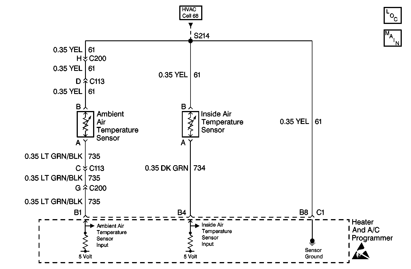
Circuit Description
The inside air temperature sensor is a thermistor that controls signal voltage to the HVAC control module (HCM). The inside air temperature sensor system contains an aspirator which pulls the air from the passenger compartment through the sensor. The HCM supplies voltage on CKT 734. When the sensor is cold, the resistance is high and the HCM will sense a high signal voltage at terminal B4, connector C2. When the sensor warms, resistance is reduced and the signal voltage is pulled low through CKT 61. Signal voltage will vary from 5 V (open circuit) to 0 V (short circuit).
Conditions for Setting the DTC
| • | The ignition is ON. |
| • | DTC B1310 is not set. |
| • | The circuit is open or shorted. |
Action Taken When the DTC Sets
| • | A default value of 24 degrees C (75 degrees F) will be used by the HCM. |
| • | The default value allows operation of the system. |
Conditions for Clearing the DTC
| • | Use a Scan Tool . |
| • | A history DTC will clear after 50 consecutive ignition cycles have occurred without a malfunction. |
| • | SBM battery voltage is interrupted. |
Test Description
The numbers below refer to the step numbers on the diagnostic table.
-
Perform the Body Control Module (SBM) Diagnostic System Check before continuing with the diagnosis of this DTC.
-
Ensures that the DTC was not set in error.
-
This step determines whether the cause of the malfunction is the sensor or an open or a short in a circuit.
-
This step determines if the IPM is malfunctioning.
-
Clear all the DTC's after the repair procedures are complete.
Step | Action | Value(s) | Yes | No |
|---|---|---|---|---|
Did you perform the BCM Diagnostic System Check? | -- | Go to Step 2 | Go to Diagnostic System Check - Body Control System in Body Control System | |
2 |
Is the specified voltage measured? | 4.5-5.5 V | Go to Step 3 | Go to Step 7 |
Did the DTC reset? | -- | Go to Step 4 | ||
Did the inside air temperature sensor voltage decrease? | -- | Go to Step 6 | Go to Step 5 | |
Is the repair complete? | -- | Go to Step 13 | -- | |
6 | Replace the sensor. Refer to Inside Air Temperature Sensor Replacement . Is the replacement complete? | -- | Go to Step 13 | -- |
7 | Measure the voltage between the sensor terminal A and ground. Refer to Measuring Voltage in Wiring Systems. Is the specified voltage measured? | 4.5-5.5 V | Go to Step 8 | Go to Step 10 |
8 | Inspect the HVAC sensor DTCs. Are all of the HVAC sensor DTCs present? | -- | Go to Step 9 | Go to Step 12 |
9 |
Is the repair complete? | -- | Go to Step 13 | -- |
10 | Measure the voltage between the heater and A/C programmer terminal B4 and ground. Refer to Measuring Voltage in Wiring Systems. Is the specified voltage measured? | 4.5-5.5 V | Go to Step 11 | Go to Step 5 |
11 | Repair the open in CKT 734 (DK GRN). Refer to Wiring Repairs in Wiring Systems. Is the repair complete? | -- | Go to Step 13 | -- |
12 | Repair the open in CKT 61 (YEL). Refer to Wiring Repairs in Wiring Systems. Is the repair complete? | -- | Go to Step 13 | -- |
Is the A/C system operating properly? | -- | Go to Diagnostic System Check - Body Control System in Body Control System. | -- |
